EP0127474B1 - Behälter zum Sammeln von Körperausscheidungen - Google Patents
Behälter zum Sammeln von Körperausscheidungen Download PDFInfo
- Publication number
- EP0127474B1 EP0127474B1 EP84303576A EP84303576A EP0127474B1 EP 0127474 B1 EP0127474 B1 EP 0127474B1 EP 84303576 A EP84303576 A EP 84303576A EP 84303576 A EP84303576 A EP 84303576A EP 0127474 B1 EP0127474 B1 EP 0127474B1
- Authority
- EP
- European Patent Office
- Prior art keywords
- container
- seams
- layers
- intermediate layers
- mouth
- Prior art date
- Legal status (The legal status is an assumption and is not a legal conclusion. Google has not performed a legal analysis and makes no representation as to the accuracy of the status listed.)
- Expired
Links
- 239000002699 waste material Substances 0.000 title claims description 5
- 238000005304 joining Methods 0.000 claims abstract description 10
- 241000973497 Siphonognathus argyrophanes Species 0.000 claims description 4
- 239000011888 foil Substances 0.000 description 82
- 239000000463 material Substances 0.000 description 13
- 238000003466 welding Methods 0.000 description 9
- 239000007788 liquid Substances 0.000 description 7
- 238000004519 manufacturing process Methods 0.000 description 5
- 239000000853 adhesive Substances 0.000 description 4
- 230000001070 adhesive effect Effects 0.000 description 4
- 238000000034 method Methods 0.000 description 4
- 210000002700 urine Anatomy 0.000 description 4
- 210000003608 fece Anatomy 0.000 description 3
- 238000004804 winding Methods 0.000 description 3
- 238000010276 construction Methods 0.000 description 2
- 238000005520 cutting process Methods 0.000 description 2
- 238000010438 heat treatment Methods 0.000 description 2
- 239000004033 plastic Substances 0.000 description 2
- 239000012815 thermoplastic material Substances 0.000 description 2
- 206010021639 Incontinence Diseases 0.000 description 1
- 238000007455 ileostomy Methods 0.000 description 1
- 238000010348 incorporation Methods 0.000 description 1
- 239000000155 melt Substances 0.000 description 1
- 230000002787 reinforcement Effects 0.000 description 1
- 230000001502 supplementing effect Effects 0.000 description 1
- 238000009333 weeding Methods 0.000 description 1
Images

Classifications
-
- A—HUMAN NECESSITIES
- A61—MEDICAL OR VETERINARY SCIENCE; HYGIENE
- A61F—FILTERS IMPLANTABLE INTO BLOOD VESSELS; PROSTHESES; DEVICES PROVIDING PATENCY TO, OR PREVENTING COLLAPSING OF, TUBULAR STRUCTURES OF THE BODY, e.g. STENTS; ORTHOPAEDIC, NURSING OR CONTRACEPTIVE DEVICES; FOMENTATION; TREATMENT OR PROTECTION OF EYES OR EARS; BANDAGES, DRESSINGS OR ABSORBENT PADS; FIRST-AID KITS
- A61F5/00—Orthopaedic methods or devices for non-surgical treatment of bones or joints; Nursing devices ; Anti-rape devices
- A61F5/44—Devices worn by the patient for reception of urine, faeces, catamenial or other discharge; Colostomy devices
Definitions
- This invention relates to a container for the collection of bodily waste, such as for example, urine and/or faeces.
- Such a container may be substantially flat in its empty condition, and be made of plastic, rubber or another flexible material, and may comprise two outer walls joined to each other by a surrounding seam, an inlet, and, if desired, an outlet, the inlet being provided with a non-return valve formed by enveloping a tube end in two intermediate layers, the layers having the same lateral extent as the outer walls of the container.
- These intermediate layers may have free edges spaced from the mouth of the tube and may lie closely against each other in an area defined longitudinally of the container by said free edges and the mouth and laterally by seams joining the intermediate layers.
- Such containers may for example be of the type in which the outer walls and the intermediate layers are joined to each other in longitudinal seams extending longitudinally of the container, forming a number of interconnected chambers.
- These containers are especially intended for the collection of faeces or urine, e.g. to be used by persons who have undergone an operation like colostomy, ileostomy or ureteromy, or especially for the collection of urine from incontinent patients.
- non-return valves formed by enveloping the end of the inlet tube in two foils, which are situated substantially in a plane comprising the central axis of the inlet tube end portion and which are delimited by the edges of the foils situated a certain distance from the tube end, e.g. 2-3 cm.
- the foils are joined by two seams which diverge from the tube end, so that the foils form a sort of extension of the inlet tube and do not impede the arriving liguid. When no liguid is arriving, the foils lie smoothly against each other preventing the liquid from returning, as a force would be needed to counteract the adhesion forces between the two foils.
- This type of nonreturn valve which in the present specification will also be termed "a foil valve”, has the advantage of being mass-producable from simple materials.
- this foil valve has until now been manufactured in two different ways in connection with containers of the present kind.
- the valve and the container are produced within the same flow of work.
- the inlet tube is enveloped in two foil webs extending over the full width of the container.
- the edges of the foils are situated transversely to the longitudinal direction at a certain distance from the tube end.
- the foils are joined around the tube end and in the abovemen- tioned two diverging seams. Subsequently, the foils are covered with two further foils forming the outer walls of the container.
- this construction involves the risk that the non-return valve may not be completely tight due to the occurrence of windings and undulations in the valve foils when the container is filled and thereby bulging, the distance between the lateral seams of the container being shortened by the bulging, which means that the valve foils are pushed towards the central line. Under such conditions the foils are not tight and flat, and the adhesion between the two foils is not sufficient to prevent pockets through which the contents of the container can be forced back through the non-return valve.
- Danish Patent Specification No. 135,928 discloses a container, which is flat in its empty condition, of plastic, rubber or another flexible material, which container comprises two outer walls joined to each other by a surrounding seam, and intermediate walls, said outer and intermediate walls being joined together in longitudinal seams extending longitudinally of the container and forming a number of interconnected chambers.
- This known container is intended to be attached to the leg of the patient.
- the container is divided into mutually interconnected chambers.
- the container may for example consist of four layers of foil joined in seams, partly to seal the container and partly to delimit the chambers.
- the chambers are arranged ;n a row and are all bordering the outer walls, while the two intermediate foils partly form intermediate walls between the individual chambers and partly lie close to portions of the outer foils.
- the chambers are always limited at the outside by the two outer foils, but the outer foils are partially supplemented with one or both of the intermediate foils.
- This supplementing represents a waste of material, the outer foils having to be dimensioned in such a way that they by themselves are able to withstand the occurring load.
- the intermediate layer or layers are not used for dividing the interior of the container into chambers, and in principle these layers could be omitted, but they have been included for productional reasons, as it is easier to produce a container, which is flat, i.e. essentially two-dimensional, in its empty condition, from four complete pieces of foil.
- a flexible container for the collection of bodily waste comprising two outer walls joined to each other by a surrounding seam, and an inlet provided with a non-return valve comprising a tube end enveloped between two intermediate layers, the intermediate layers having the same lateral extent as said outer walls of the container, wherein the intermediate layers have free edges spaced from the mouth of the tube and lie closely against each other in an area defined longitudinally of the container by said free edges and the said tube mouth and laterally by seams joining the intermediate layers, characterised in that the intermediate layers extend longitudinally of the container to a greater distance from the mouth than the distance from the mouth to the free edges, the free edges bordering on an opening in each of the intermediate layers, and said openings delimiting the non-return valve.
- the non- return valve can lie freely in the container in the same way as a separately produced foil valve, and the foil of the valve will not be pressed together in the lateral direction. In this way the likelihood of windings and pockets occurring in the foils of the valve is reduced and conseguently the risk of leakages too.
- the openings delimiting the non-return valve may advantageously be substantially U- or horseshoeshaped. It is further advantageous that the laterally defining seams are disposed a short distance from the legs of the U- or horseshoe-shaped openings and converge towards the tube mouth so as to lie- tightly around the tube at said mouth, and that the legs extend substantially to the region surrounding the mouth. This ensures that the non-return valve is completely disengaged from the portions of the intermediate layers not forming part of the non-return valve. In this way the valve is protected optimally against lateral stresses, the risk of leakages being thereby avoided.
- the ratio of the distance between the mouth and the free edges to the distance between the seams at the free edges should be between 1:1 and 3:1, and preferably between 1.5:1 and 2:1.
- the intermediate layers have the same extent as the outer walls in both the longitudinal direction and the lateral direction and all four layers are joined to each other in the surrounding seam, Preferably forming a flange situated outside the seam.
- This ensures the same number of foil layers and thereby the same thickness of the material in the entire surrounding seam in which the layers are joined.
- the layers are joined by welding.
- intermediate layers have the same extent as the outer walls both in the longitudinal and lateral directions
- the intermediate layers may be particularly advantageous for use in connection with the known type of containers, which have intermediate walls in addition to the outer walls, whereby the outer walls and the intermediate walls are joined to each other in longitudinal seams running in the length direction of the container and forming a number of interconnected chambers.
- the intermediate walls may advantageously be formed by the intermediate layers, which are joined to each other by a plurality of not through-going primary seams and to the respective adjacent outer wall by a plurality of not through-going secondary seams, said secondary seams being displaced with respect to said primary seams, and the intermediate layers having one or more apertures, preferably near the top or the bottom of the container.
- the embodiment described above offers the further advantage over the container disclosed in Danish patent specification No. 135,928 that the intermediate layers are better utilized for the division into chambers.
- the intermediate layers are better utilized for the division into chambers.
- each chamber being consequently smaller, e.g. 10 chambers compared to a division into only 5 chambers obtained according to an embodiment disclosed in the Danish patent specification mentioned above, in which case the number of joints is of the same order of magnitude.
- This improved utilization of the foil material may result from the mutual arrangement of the primary and secondary seams, in accordance with which care is taken that two or three foils do not to a considerable extent lie closely against each other without utilization of space between them as a chamber in the container.
- the container is also provided with a number of interconnected chambers formed by intermediate walls joined in longitudinal seams.
- the intermediate walls are formed by two wall layers having the same lateral extent as the outer walls and extending from a level below a downward edge of the intermediate layers to the downward longitudinal end of the container.-said wall layers being joined with each other by a plurality of not through-going primary seams and to the respective adjacent outer walls by a plurality of not through-going secondary seams, said secondary seams being displaced with respect to said primary seams, and the wall layers having one or more apertures disposed near the bottom of the container.
- further apertures can be omitted in the top part of the container, i.e. only the opening delimiting the non-return valve must be present in the top part.
- the intermediate walls are formed by two wall layers having the same lateral extent as the outer walls and extending from a level below a downward edge of the intermediate layers to a level disposed a short distance above the surrounding seam in the bottom longitudinal end of the container, said wall layers being joined to each other by a plurality of notthrough-going primary seams and to the respective adjacent outer wall by a plurality of not through-going secondary seams, said secondary seams being displaced with respect to said primary seams.
- apertures near the bottom of the container can be omitted.
- the last-mentioned two embodiments give a better utilization of the foil layers for division into chambers as compared with the division arrangement proposed in Danish patent specification No. 135.928.
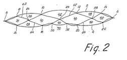
- the container illustrated in Figures 1 and 2 comprises four foils forming two outer walls 2, 4, and two intermediate layers 62, 64, which foils are joined to form a closed container by using an adhesive, by welding or, by another joining method to form a surrounding seam 6.
- the container has an inlet 54 with a valve of the type termed a foil valve in this specification, and an outlet 58 with an outlet valve 60.
- the outlet 58 and the outlet valve 60 may be omitted, whereby the joint seam 6 will be continuous in the bottom part of the container.
- the foil valve is made by enveloping the end of the inlet 54, which is in the present case formed by a tube end 76 between the foils constituting the intermediate layers 62, 64.
- the foil valve comprises two foil layers lying closely against each other but only held together by the mutual adhesion between the two foils. This area is laterally delimited by two joint seams 72, 74 joining the two foils, e.g. formed by welding; the area is downwardly delimited by the concurrent free edges 80 forming the opening of the valve leading into the interior of the container.
- the area 56 is upwardly delimited by the mouth 78 of the tube end 76.
- the welded seams 72, 74 extend right up to the surrounding seam 6, which is close to the tube 76.
- the area 56 is only open through the mouth 78 and between the free edges 80.
- the function of the foil valve is that a liquid can easily flow through the mouth 78 of the tube 76 and into the area 56, in which the two foils are pressed from each other by the liguid which then flows into the container between the two free edges 80.
- the two foils When no liquid flows from the tube 76 into the container, the two foils will lie closely against each other in the area 56 with a mutual adhesion sufficient to prevent the liquid from being forced from the container into the area 56 between the foils, but not sufficient to give a perceptible resistance to liquid flowing from the mouth 78 into the area.
- the intermediate layers 62, 64 have the same extent as the two outer walls 2, 4. In the embodiment shown they also have the same extent as the outer walls in the length direction. However, it is sufficient that in the length direction they extend to a distance from the mouth 78, which is greater than the distance (a) from the mouth 78 to the free edges 80. In other words, it is not the downward edges of the intermediate layers 62, 64, which are to function as an opening in the foil valve in the form of the free edges 80. On the contrary, these free edges are attained by providing the intermediate layers with an opening or aperture 66. This aperture 66 can delimit the foil valve, e.g.
- the intermediate layers 62, 64 were supplied in the form of rolled up foil webs having interruptions in the form of incisions in one of the side edges, whereby the foil webs would tend to run askew or aslant or even to crack or tear. If, on other hand, the intermediate layers extend at least some distance beyond the aperture 66, e.g. with-the downward edge situated shown with a dot-and-dash line 94 in Figure 1, there will be an uninterrupted edge along the line 94, whereby the guiding and controlling of the foil webs to be used for forming the intermediate layers 62, 64 will be facilitated.
- the intermediate layers have the same extent also in the length direction as the outer walls 2, 4. This ensures that the same number of foil layers will be joined throughout the whole of the surrounding seam 6. This is advantageous in case of joining by welding, the controlling of the welding being facilitated. If some areas have only two layers of foil and some other areas four layers, a particular risk of leakages in the weld seam 6 would exist at the shifts from two to four layers of foil.
- the outer wall 2, 4 and the intermediate layers 62, 64 together form a flange 96, which stiffens the container.
- the flange 96 may be further stiffened, e.g. with an additional surrounding seam (not shown). This flange may suitably be used for the mounting of support means (not shown) for supporting the container, e.g. in such a way that it can be worn by a patient.
- the intermediate layers 62, 64 are further used for dividing the container into interconnected chambers 34, 36, 38, 40, 42, 44, 46, 48, 50, 52.
- This division is made by joining the two intermediate layers 62, 64 by an adhesive, by welding or by using any other joining technique, in seams 24, 26, 28.
- the top foil layer, i.e. the outer wall 2 ( Figure 2) is joined with the adjacent intermediate layers 62 by use of an adhesive, by weeding or by any other means known'per se, in seams 8,10,12, 14, and similarly the bottom foil layer, i.e. the outer wall 4, is joined with the adjacent intermediate layer 64 in seams 16, 18, 20, 22.
- Two additional joints 30, 32 are provided on the back of the container giving the container a cross-section with a recess 70. This recess facilitates the securing of the container to the leg of the user.
- the intermediate layers 62, 64 extend further upwards and downwards than the surrounding seam, it is necessary that the intermediate layers are provided with apertures 66, 86, 88 near the top of the container and with further apertures 68, 90, 92 near the bottom of the container and close to the outlet 58. This ensures that the chambers are mutually connected. It is also possible in case the intermediate layers do not have the same extent as the outer walls 2, 4 in the length direction to utilize the intermediate layers for the division into chambers if the downward edge.of the intermediate layers is situated at a short distance from the lower part of the container, i.e. at a short distance from the surrounding seam 6 in the area around the outlet 58 of the container, e.g. as shown by a dot-and-dash line 100 in Figure 1. In that case, the apertures 68, 90, 92 near the bottom of the container can be omitted.
- the container may be provided with additional foils in the form of two wall layers having the same extent as the outer walls in the width direction and extending from a level shown with a dot-and-dash line 98 in Figure 1, below the downward edge 94 of the intermediate layers, to a level near the bottom of the container.
- the wall layers can form the intermediate walls if the wall layers are joined to each other in a number of not through-going primary seams and with the respective adjacent outer walls 2, 4 in a number of secondary seams, said secondary seams being displaced with respect to said primary seams.
- the primary and secondary seams can be situated as shown in Figure 1, but of course only extending within the wall layers.
- the space between the intermediate layers and the wall layers means that the apertures 86, 88 shown in Figure 1 can be omitted.
- the downward edge of the wall layers may either extend beyond the seam 6 in the bottom part of the container, in which case the wall layers form a portion of the flange 96 and they should be provided with apertures 68, 90, 92 near the bottom of the container, or the downward edge of the wall layers may be located a short distance above the surrounding seam 6 in the bottom end of the container, e.g. as shown by the line 100 in Figure 1, in which case the apertures 68, 90, 92 may be omitted.
- a container in which the non-return valve has the same reliability as the one obtained when the non-return valve is provided in a separate step by enveloping a tube end in two foils and cutting away the superfluous foil material, i.e. avoiding the drawbacks of leakage in connection with foil valves, which for productional reasons are produced by using foils having the same extent as the outer walls in the width direction of the container.
- the container according to the invention may for example be made of a thermoplastic material, which can be joined by welding.
- a thermoplastic material is PVC-foil.
- the container can also be made of rubber or another flexible material, e.g. using an adhesive for the joining.
Landscapes
- Health & Medical Sciences (AREA)
- General Health & Medical Sciences (AREA)
- Veterinary Medicine (AREA)
- Orthopedic Medicine & Surgery (AREA)
- Engineering & Computer Science (AREA)
- Biomedical Technology (AREA)
- Heart & Thoracic Surgery (AREA)
- Vascular Medicine (AREA)
- Life Sciences & Earth Sciences (AREA)
- Animal Behavior & Ethology (AREA)
- Epidemiology (AREA)
- Nursing (AREA)
- Public Health (AREA)
- Sampling And Sample Adjustment (AREA)
- Investigating Or Analysing Biological Materials (AREA)
- Bag Frames (AREA)
- Medicines Containing Material From Animals Or Micro-Organisms (AREA)
- Tubes (AREA)
- External Artificial Organs (AREA)
- Accommodation For Nursing Or Treatment Tables (AREA)
- Measurement Of The Respiration, Hearing Ability, Form, And Blood Characteristics Of Living Organisms (AREA)
- Medical Preparation Storing Or Oral Administration Devices (AREA)
Claims (11)
Priority Applications (1)
| Application Number | Priority Date | Filing Date | Title |
|---|---|---|---|
| AT84303576T ATE36643T1 (de) | 1983-05-27 | 1984-05-25 | Behaelter zum sammeln von koerperausscheidungen. |
Applications Claiming Priority (2)
| Application Number | Priority Date | Filing Date | Title |
|---|---|---|---|
| DK2379/83 | 1983-05-27 | ||
| DK237983A DK149402C (da) | 1983-05-27 | 1983-05-27 | Beholder til opsamling af urin og/eller faekalier |
Publications (2)
| Publication Number | Publication Date |
|---|---|
| EP0127474A1 EP0127474A1 (de) | 1984-12-05 |
| EP0127474B1 true EP0127474B1 (de) | 1988-08-24 |
Family
ID=8111975
Family Applications (1)
| Application Number | Title | Priority Date | Filing Date |
|---|---|---|---|
| EP84303576A Expired EP0127474B1 (de) | 1983-05-27 | 1984-05-25 | Behälter zum Sammeln von Körperausscheidungen |
Country Status (7)
| Country | Link |
|---|---|
| US (1) | US4581763A (de) |
| EP (1) | EP0127474B1 (de) |
| AT (1) | ATE36643T1 (de) |
| DE (1) | DE3473561D1 (de) |
| DK (1) | DK149402C (de) |
| ES (1) | ES287377Y (de) |
| NO (1) | NO155525C (de) |
Families Citing this family (35)
| Publication number | Priority date | Publication date | Assignee | Title |
|---|---|---|---|---|
| US5116139A (en) * | 1989-09-08 | 1992-05-26 | American Innotex, Inc. | Fluid containment bag |
| US5354132A (en) * | 1987-01-14 | 1994-10-11 | American Innotek, Inc. | Fluid containment bag |
| US5531724A (en) * | 1987-01-14 | 1996-07-02 | American Innotek, Inc. | Fluid containment bag |
| EP0591144B1 (de) * | 1990-09-12 | 1999-08-25 | American Innotek, Inc. | Flüssigkeitssack |
| DK170519B1 (da) * | 1992-03-04 | 1995-10-16 | Coloplast As | Opsamlingsposer og fremgangsmåder til fremstilling af sådanne poser |
| US5451179A (en) * | 1992-04-08 | 1995-09-19 | Vonco Products, Inc. | Inflatable flexible pouch with inner inflatable structure |
| US5336123A (en) * | 1992-04-08 | 1994-08-09 | Vonco Products, Inc. | Inflatable flexible pouch |
| US5483999A (en) * | 1993-03-15 | 1996-01-16 | Merit Medical Systems, Inc. | Waste collection system for containment and disposal of contaminated fluids |
| US5549707A (en) * | 1994-01-18 | 1996-08-27 | Contour Fabricators, Inc. | Fluid collection apparatus |
| JPH08131470A (ja) * | 1994-11-14 | 1996-05-28 | Charles David Cawood | 集尿装置 |
| WO1997039705A1 (en) * | 1996-04-22 | 1997-10-30 | American Innotek, Inc. | Fluid containment bag |
| US5792127A (en) * | 1996-10-23 | 1998-08-11 | Marran; James E. | Urine collection and drainage device |
| US6132407A (en) | 1997-02-06 | 2000-10-17 | C. R. Bard, Inc. | Outlet tube device for urinary drainage bag |
| US6736803B2 (en) * | 1999-01-13 | 2004-05-18 | Cawood Family Limited Partnership | Urine bag and self-retracting drain tube therefor |
| US6045542A (en) * | 1999-01-13 | 2000-04-04 | Cawood Family Limited Partnership | Urine collection device |
| US6471680B1 (en) | 1999-01-13 | 2002-10-29 | Cawood Family Limited Partnership | Urine bag and self-retracting drain tube therefor |
| US20020103467A1 (en) | 2001-01-31 | 2002-08-01 | Kubalak Thomas P. | Urine collection bags for urinary catheter systems |
| US7001370B2 (en) | 2001-01-31 | 2006-02-21 | Mentor Corporation | Urine collection bags for urinary catheter systems |
| US6719017B1 (en) | 2002-01-10 | 2004-04-13 | Merit Medical Systems, Inc. | Waste collection system for containment and disposal of contaminated fluids |
| USD502993S1 (en) | 2002-01-10 | 2005-03-15 | Merit Medical Systems, Inc. | Waste collection container |
| GB2390547B (en) * | 2003-04-29 | 2004-07-28 | Mentor Medical Ltd | Medical waste collection device |
| DE602004012732D1 (de) | 2003-05-14 | 2008-05-08 | Unomedical As | Beutel zur flüssigkeitsaufnahme |
| PL1624834T3 (pl) * | 2003-05-22 | 2008-07-31 | Unomedical As | Zespół zaworowy jednorazowego użytku do regulowania przepływu moczu |
| EP1804743B1 (de) * | 2003-11-13 | 2013-03-20 | Nada Dorothy Manojlovic | Harnsammelbeutel |
| US7462171B2 (en) * | 2006-02-24 | 2008-12-09 | Tyco Healthcare Group Lp | Urine collection bag with angled valve support |
| US20070203464A1 (en) * | 2006-02-24 | 2007-08-30 | Green Kurt E | Urine collection bag with integral anti-reflux valve |
| US8328734B2 (en) | 2006-02-24 | 2012-12-11 | Covidien Lp | Urine meter with improved drain construction |
| US20070239121A1 (en) * | 2006-04-11 | 2007-10-11 | Stephen Tully | Adjustable drain loop for urine collection system |
| US7645968B2 (en) | 2006-06-30 | 2010-01-12 | Tyco Healthcare Group Lp | Method for securing a urine meter to a urine bag |
| DK2073861T3 (da) | 2006-10-17 | 2015-04-13 | Bard Inc C R | Affaldshåndteringssystem |
| WO2009015152A1 (en) * | 2007-07-22 | 2009-01-29 | C.R. Bard, Inc. | Waste management system |
| US8088114B1 (en) * | 2008-03-25 | 2012-01-03 | Pauze Marilyn B | Urostomy bag cover system |
| US20110087181A1 (en) * | 2009-10-13 | 2011-04-14 | Richard Bidwell | External catheter tube |
| US10022261B1 (en) * | 2017-05-31 | 2018-07-17 | Bioderm, Inc. | Incontinence device with atmospheric equilibrium valve assembly |
| GB2620397A (en) * | 2022-07-05 | 2024-01-10 | Clinisupplies Ltd | A catheter bag and connections and accessories therefor |
Family Cites Families (8)
| Publication number | Priority date | Publication date | Assignee | Title |
|---|---|---|---|---|
| GB1349517A (en) * | 1970-06-18 | 1974-04-03 | B H Christensen | Mounting of a hose end in an opening |
| US3797734A (en) * | 1972-02-04 | 1974-03-19 | R Fleury | Disposable bags |
| DE7211842U (de) * | 1972-03-28 | 1972-08-24 | Fresenius E Kg | Urometer |
| US3823716A (en) * | 1972-08-14 | 1974-07-16 | Simpla Plastics | Urinary drainage devices |
| SE386365B (sv) * | 1973-07-25 | 1976-08-09 | L Brendling | Behallare av plast, gummi eller annat bojligt material, spec. avsedd for uppsamling av urin och/eller fekalier |
| GB1528611A (en) * | 1975-01-15 | 1978-10-18 | Matburn Ltd | Drainage bag |
| US4421509A (en) * | 1981-06-15 | 1983-12-20 | Hollister Incorporated | Leg bag for urinary incontinence |
| US4462510A (en) * | 1981-06-30 | 1984-07-31 | Kingsdown Medical Consultants Limited | Tap for drainage bag |
-
1983
- 1983-05-27 DK DK237983A patent/DK149402C/da not_active IP Right Cessation
-
1984
- 1984-05-25 NO NO842093A patent/NO155525C/no not_active IP Right Cessation
- 1984-05-25 ES ES1984287377U patent/ES287377Y/es not_active Expired
- 1984-05-25 AT AT84303576T patent/ATE36643T1/de not_active IP Right Cessation
- 1984-05-25 DE DE8484303576T patent/DE3473561D1/de not_active Expired
- 1984-05-25 EP EP84303576A patent/EP0127474B1/de not_active Expired
- 1984-05-29 US US06/614,630 patent/US4581763A/en not_active Expired - Lifetime
Also Published As
| Publication number | Publication date |
|---|---|
| ES287377Y (es) | 1986-07-16 |
| NO155525B (no) | 1987-01-05 |
| ES287377U (es) | 1985-12-16 |
| NO842093L (no) | 1984-11-28 |
| NO155525C (no) | 1987-04-22 |
| DK149402B (da) | 1986-06-02 |
| DK237983D0 (da) | 1983-05-27 |
| EP0127474A1 (de) | 1984-12-05 |
| DK237983A (da) | 1984-11-28 |
| US4581763A (en) | 1986-04-08 |
| DE3473561D1 (en) | 1988-09-29 |
| DK149402C (da) | 1986-11-10 |
| ATE36643T1 (de) | 1988-09-15 |
Similar Documents
| Publication | Publication Date | Title |
|---|---|---|
| EP0127474B1 (de) | Behälter zum Sammeln von Körperausscheidungen | |
| EP2642959B1 (de) | Aufsammelbehälter von flüssigen ausscheidungen | |
| US4300560A (en) | Ostomy bag having a bottom drain valve | |
| CA2648365C (en) | Collecting bag having improved closure and method of manufacturing such a collecting bag | |
| EP0117016B1 (de) | Einwegventilanordnung für einen Ostomiebeutel oder dergleichen | |
| EP0294246B1 (de) | Venöses Reservoir | |
| KR950009535B1 (ko) | 테두리 보호된 액체용 팩, 그의 제조방법 및 장치 | |
| US12440369B2 (en) | Ostomy appliance | |
| EP0616948B1 (de) | Gefrierformbeutel | |
| AU2011333994B2 (en) | A pouch for collecting liquid excretions | |
| GB2080116A (en) | Drainage bag | |
| EP1804743B1 (de) | Harnsammelbeutel | |
| AU2024281689A1 (en) | Reusable incontinence underpants for men | |
| GB2633101A (en) | An ostomy appliance |
Legal Events
| Date | Code | Title | Description |
|---|---|---|---|
| PUAI | Public reference made under article 153(3) epc to a published international application that has entered the european phase |
Free format text: ORIGINAL CODE: 0009012 |
|
| AK | Designated contracting states |
Designated state(s): AT BE CH DE FR GB IT LI NL SE |
|
| 17P | Request for examination filed |
Effective date: 19850530 |
|
| 17Q | First examination report despatched |
Effective date: 19860509 |
|
| R17C | First examination report despatched (corrected) |
Effective date: 19860509 |
|
| D17Q | First examination report despatched (deleted) | ||
| GRAA | (expected) grant |
Free format text: ORIGINAL CODE: 0009210 |
|
| AK | Designated contracting states |
Kind code of ref document: B1 Designated state(s): AT BE CH DE FR GB IT LI NL SE |
|
| PG25 | Lapsed in a contracting state [announced via postgrant information from national office to epo] |
Ref country code: NL Effective date: 19880824 Ref country code: LI Effective date: 19880824 Ref country code: CH Effective date: 19880824 Ref country code: BE Effective date: 19880824 Ref country code: AT Effective date: 19880824 |
|
| REF | Corresponds to: |
Ref document number: 36643 Country of ref document: AT Date of ref document: 19880915 Kind code of ref document: T |
|
| REF | Corresponds to: |
Ref document number: 3473561 Country of ref document: DE Date of ref document: 19880929 |
|
| ITF | It: translation for a ep patent filed | ||
| ET | Fr: translation filed | ||
| REG | Reference to a national code |
Ref country code: CH Ref legal event code: PL |
|
| NLV1 | Nl: lapsed or annulled due to failure to fulfill the requirements of art. 29p and 29m of the patents act | ||
| PLBE | No opposition filed within time limit |
Free format text: ORIGINAL CODE: 0009261 |
|
| STAA | Information on the status of an ep patent application or granted ep patent |
Free format text: STATUS: NO OPPOSITION FILED WITHIN TIME LIMIT |
|
| 26N | No opposition filed | ||
| ITTA | It: last paid annual fee | ||
| EAL | Se: european patent in force in sweden |
Ref document number: 84303576.7 |
|
| REG | Reference to a national code |
Ref country code: GB Ref legal event code: IF02 |
|
| PGFP | Annual fee paid to national office [announced via postgrant information from national office to epo] |
Ref country code: SE Payment date: 20030507 Year of fee payment: 20 |
|
| PGFP | Annual fee paid to national office [announced via postgrant information from national office to epo] |
Ref country code: FR Payment date: 20030508 Year of fee payment: 20 |
|
| PGFP | Annual fee paid to national office [announced via postgrant information from national office to epo] |
Ref country code: GB Payment date: 20030519 Year of fee payment: 20 |
|
| PGFP | Annual fee paid to national office [announced via postgrant information from national office to epo] |
Ref country code: DE Payment date: 20030605 Year of fee payment: 20 |
|
| PG25 | Lapsed in a contracting state [announced via postgrant information from national office to epo] |
Ref country code: GB Free format text: LAPSE BECAUSE OF EXPIRATION OF PROTECTION Effective date: 20040524 |
|
| REG | Reference to a national code |
Ref country code: GB Ref legal event code: PE20 |
|
| EUG | Se: european patent has lapsed |