EP0125902A2 - Récipiant pour un dispositif de pesage automatique - Google Patents
Récipiant pour un dispositif de pesage automatique Download PDFInfo
- Publication number
- EP0125902A2 EP0125902A2 EP84303202A EP84303202A EP0125902A2 EP 0125902 A2 EP0125902 A2 EP 0125902A2 EP 84303202 A EP84303202 A EP 84303202A EP 84303202 A EP84303202 A EP 84303202A EP 0125902 A2 EP0125902 A2 EP 0125902A2
- Authority
- EP
- European Patent Office
- Prior art keywords
- hopper
- gate
- discharge port
- weighing apparatus
- link
- Prior art date
- Legal status (The legal status is an assumption and is not a legal conclusion. Google has not performed a legal analysis and makes no representation as to the accuracy of the status listed.)
- Granted
Links
- 238000005303 weighing Methods 0.000 title claims abstract description 48
- 239000000463 material Substances 0.000 claims abstract description 5
- 230000003014 reinforcing effect Effects 0.000 claims description 12
- 239000012212 insulator Substances 0.000 claims description 3
- 235000013611 frozen food Nutrition 0.000 description 5
- JOYRKODLDBILNP-UHFFFAOYSA-N Ethyl urethane Chemical compound CCOC(N)=O JOYRKODLDBILNP-UHFFFAOYSA-N 0.000 description 3
- 235000013305 food Nutrition 0.000 description 3
- XLYOFNOQVPJJNP-UHFFFAOYSA-N water Substances O XLYOFNOQVPJJNP-UHFFFAOYSA-N 0.000 description 3
- 238000004806 packaging method and process Methods 0.000 description 2
- 238000003466 welding Methods 0.000 description 2
- 238000010276 construction Methods 0.000 description 1
- 238000007599 discharging Methods 0.000 description 1
- 239000012778 molding material Substances 0.000 description 1
- 238000002360 preparation method Methods 0.000 description 1
- 230000000717 retained effect Effects 0.000 description 1
Images


Classifications
-
- G—PHYSICS
- G01—MEASURING; TESTING
- G01G—WEIGHING
- G01G13/00—Weighing apparatus with automatic feed or discharge for weighing-out batches of material
- G01G13/16—Means for automatically discharging weigh receptacles under control of the weighing mechanism
- G01G13/18—Means for automatically discharging weigh receptacles under control of the weighing mechanism by valves or flaps in the container bottom
Definitions
- This invention relates to an automatic weighing apparatus and, more particularly, to improvements in a hopper in an automatic weighing apparatus suitable for weighing frozen foods.
- An automatic weighing apparatus now in practical use operates by supplying articles to a plurality of weighing machines, computing combinations of weight values obtained from the weighing machines, selecting a combination of the weight values the sum total whereof is equal to a predetermined fixed weight, and discharging only the articles contained in the weighing machines corresponding to the selected combination (referred to as the "optimum combination"), whereby there is obtained a batch of the articles the weight whereof is equal or closest to the fixed weight.
- each of the weighing machines is equipped with a weighing hopper for accommodating a batch of articles therein, and with a pool hopper disposed above the weighing hopper for quickly supplying the weighing hopper with the next batch of articles to be weighed when the previously weighed batch of articles has been discharged from the weighing hopper.
- each of these hoppers has a hopper body a the lower end portion of which is provided with a discharge port a' from which articles are discharged.
- Each hopper further includes an openable and closable gate b provided at the discharge port a', a toggle-type link mechanism c actuatable under the control of an external force for opening and closing the gate b, and which is also operable to lock the gate shut when the gate is closed, and a spring d which acts through the link mechanism c to bias the gate b in the closing direction.
- the link mechanism c is incapable of bringing the gate b to the home position, which is necessary to lock the gate in the closed state.
- the link mechanism c only a small component of the biasing force applied by the spring d in the closing direction is capable of acting upon the gate b through the link mechanism c.
- the gate b tends to open naturally under the weight of the articles contained in the hopper body a, thereby contributing to leakage of the articles in the manner described above.
- An object of the present invention is to provide a hopper for use in an automatic weighing apparatus, wherein a gate provided on the hopper can be brought to a predetermined closing position perfectly when the gate is to be closed, even if water contained in a frozen food or in the air forms a frozen deposit at the discharge port of the hopper when the automatic weighing apparatus is used to weigh out such foods or finds use in a freezer chamber.
- Another object of the present invention is to provide a hopper for use in an automatic weighing apparatus, wherein weighed articles are prevented from leaking from the hopper owing to frozen deposits causing deformation at the discharge port of the hopper.
- Still another object of the present invention is to provide a hopper for use in an automatic weighing apparatus, wherein residua from articles such as foodstuffs are prevented from attaching themselves to the inner wall of the hopper.
- a hopper comprising a hopper body having a discharge port at the lower end thereof, and a gate swingably supported at the upper edge of the hopper body for opening and closing the discharge port, at least the edge portion of the gate being formed of a flexible material for resiliently contacting the inner surface of the discharge port.
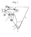
- the automatic weighing apparatus has a.base 10 above the central portion of which is supported a platform 12 by means of a plurality of support legs 11. Disposed above the central portion of the platform 12 is a circular dispersing table 14 supported on the platform 12 by a vibrating device 13. Articles which drop onto the dispersing table 14 from a chute of a supply conveyor (not shown) migrate toward the outer edge of the table owing to vibration applied thereto by the vibrating device 13. The articles drop successively from the outer edge of the dispersing table 14 into a plurality of underlying, radially arranged troughs 16 surrounding the table.
- Each trough 16 is supported on the platform 12 by a corresponding vibrating device 1.5 the vibratory action of which causes the articles received from the dispersing table 14 to migrate from one end of the trough to the other or outer end, from which end the articles fall.
- Supported on the platform 12 are a plurality of pool hoppers 2 each of which corresponds to one of the troughs 6.
- Each pool hopper 2 is disposed below the outer end of the corresponding trough 6 to receive the articles which fall from trough, and is provided with an openable and closable gate 21.
- a plurality of weighing machines 3 are disposed below corresponding ones of the pool hoppers 11.
- Each weighing machine 3 comprises a weight sensor 4 mounted on the base l, and a weighing hopper 5 attached to the weight sensor 4 so as to underlie the corresponding pool hopper 2.
- Each weighing hopper 5 is provided with an openable and closable gate 51.
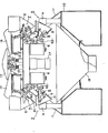
- a plurality of hopper drive units 6 depend from the lower side of the platform 12.
- Each hopper drive unit 6 corresponds to one cooperating set of the pool hoppers 11 and weighing hoppers 2, the latter underlying the former as mentioned above.
- Each hopper drive unit 6 is equipped with two push-rods 61a, 61b, the distal ends of which have respective operating members 611, 612 attached thereto.
- the operating member 611 When the push-rod 61 is thrust outwardly, the operating member 611 opens the gate 21 of the corresponding pool hopper 2 via a link mechanism 7. Likewise, when the push-rod 62 is thrust outwardly, the operating member 621 opens the gate 51 of the corresponding weighing hopper 5 via a link mechanism 8.
- the hopper drive units 6 are actuated by a single motor 17 depending from the lower side of the platform 12 at the central portion thereof.
- Numeral 18 denotes a collecting chute supported on the base 10 below the weighing hoppers 5 for receiving the articles discharged by the weighing hoppers 5 and for supplying the articles to a packaging apparatus.
- the pool hopper 2 comprises a main body 20 having an upper opening and a lower article discharge port 201. Attached to the hopper main body 20 as by welding are a bracket 210 for mounting the hopper main body on the platform 12, and a bracket 220 supporting a link mechanism 7.
- the link mechanism 7, which actuates the gate 21 for opening and closing the discharge port 201 of the hopper main body 20, comprises a drive link 71 pivotably supported by a shaft 231 on an end 221 of the bracket 220 that projects from one side of the hopper main body 20, a follower link 72 having one end 721 thereof attached to a rotary shaft 232 of the gate 21 so as to be swingably movable with the gate 21, and an intermediate link 73 interconnecting the other end 722 of the follower link 72 and one end 711 of the drive link 71 by means of shafts 233 and 234.
- a return spring 240 is stretched between the other end 712 of the drive link 71 and an end portion 222 of the bracket 220 that extends away from the drive link 71, whereby the drive link 71 is biased for rotation in the direction of the arrow E at all times about the shaft 231.
- a stopper 250 is attached to the bracket 220 so that an extension 712 of the drive link 71 will come into abutting contact therewith to limit the abovementioned rotation of the drive link 71. With the extension 712 of the drive link 71 in abutting contact with the stopper 250, as shown in Fig. 3, the link mechanism 7 will cause the gate 21 to close the discharge port 201.
- the link mechanism 7 acts as a toggle mechanism, so that a substantially linear relationship is established among the shaft 231 of the drive link 71, the shaft 234 connecting the drive link 71 and the intermediate link 73, and the shaft 233 connecting the intermediate link 234 and the follower link 72, as shown in Fig. 3.
- An operating lever 74 is secured to the drive link 71 for being pushed by the operating member 611 attached to the distal end of the push rod 61 of drive unit 6. When the operating lever 74 is pushed, the link mechanism 7 responds by opening the gate 21.
- the gate 21 comprises a base plate 211 axially secured to both sides of the hopper body 20 by the shafts 232, a reinforcing frame 212 fixed to the upper edge of the base plate 211, and a U-shaped flexible sheet 213 made of urethane or the like and affixed to the base plate 211 at the left, right and lower edges thereof.
- the flexible sheet 213 is affixed to the base plate 211 so as to surround the same from its left, right and lower sides.
- the flexible sheet 213 penetrates the interior of the discharge port 201 and comes into intimate contact with the inner side surfaces 20a, 20b of the hopper body 20, and with the inner surface 20c of the hopper body in the vicinity of the lower edge thereof.
- the flexible sheet 213 is embraced by the base plate 211 and a U-shaped holder plate 214 and is retained by tightening nuts 216 on a plurality of screws 215, which project from the base plate 211, from the side of the holder plate 214.
- a reinforcing member 217 Secured to the central portion of the base plate 211 is a reinforcing member 217 having an L-shaped cross section. The reinforcing member 217 .serves composition the flexible sheet 213 and the holder plate 214.
- Articles are dispsersively supplied from the dispersing table 14 through the troughs 16 and the pool hoppers 2 into the weighing hoppers 5 of the weighing machines 3, and are then weighed by the weight sensors 4 constituting the weighing machines 3. An optimum combination of measured weights is selected to obtain the prescribed fixed weight.
- the articles in the weighing hoppers 5 of the weighing machines 3 corresponding to the selected combination are discharged en masse into the underlying collecting chute 18 by opening the gates 51 of these weighing hoppers through operation of the corresponding drive units 6.
- the discharged articles are collected by the chute 18 and then supplied to a packaging apparatus (not shown) disposed below the collecting chute 18.
- the weighing hoppers 5 that have discharged their articles are immediately resupplied by the corresponding pool hoppers 2 through operation of the corresponding drive units 6. This is in preparation for the next cycle of the weighing operation.
- the pool hoppers 2 in the foregoing automatic weighing apparatus operate in the following manner.
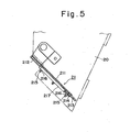
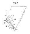
- Figs. 6 through 10 illustrate a second embodiment of the present invention, in which the invention is directed to the weighing hoppers 5 of the automatic weighing apparatus shown in Fig. 2.
- the weighing hopper 5 comprises a main body 50 having an upper opening and a lower article discharge port 501.
- the inner surface of the hopper main body 50 is coated with a heat insulator 505.
- Attached to the hopper main body 50 as by welding are a bracket 510 for mounting the hopper main body on the corresponding weight sensor 4, and a pair of brackets 520, 520, one on either side, for supporting a link mechanism 8.
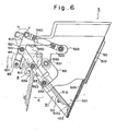
- the link mechanism 8 which actuates the gate 51 for opening and closing the discharge port 501 of the hopper main body 50, comprises a drive link 81 pivotably supported by a shaft 231 extending"between end portions 521, 521 of the brackets 520, 520, which end portions project from one side of the hopper main body 50, a follower link 82 having one end 821 thereof attached to a rotary shaft 532 of the gate 51 so as to be swingably movable with the gate 51, and an intermediate link 83 interconnecting the other end 822 of the follower link 82 and one end 811 of the drive link 81 by means of shafts 533 and 534.
- a return spring 540 is stretched between the other end 812 of the drive link 81 and an end portion 522 of the bracket 520 that extends away from the drive link 81, whereby the drive link 81 is biased for rotation in the direction of the arrow J at all times about the shaft 531.
- a stopper 550 is attached to the bracket 520 so that an extension 812 of the drive link 81 will come into abutting contact therewith to limit the abovementioned rotation of the drive link 81. With the extension 812 of the drive link 81 in abutting contact with the stopper 550, as shown in Fig. 6, the link mechanism 8 will cause the gate 51 to close the discharge port 501.
- the link mechanism 8 acts as a toggle mechanism, so that a substantially linear relationship is established among the shaft 531, the shaft 533 and the shaft 534, as shown in Fig. 6.
- An operating lever 85 is secured to the drive link 81 via a connecting member 84 for being pushed by the operating member 621 attached to the distal end of the push rod 62 of drive unit 6.
- the link mechanism 8 responds by opening the gate 51.
- the present embodiment includes a return spring 541 interposed between the gate 51 and the hopper body 50 for directly biasing the gate 51 in the closing direction.
- the return spring 541 is illustrated in Fig. 7.
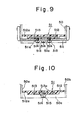
- the gate 51 comprises a generally T-shaped frame 511 axially supported by the brackets 520, 520 attached to both sides of the hopper body 50, one end of the frame 511 being secured to the follower link 82 of the link mechanism 8, a gate body 512 comprising a flexible sheet of urethane or the like and having the upper portion of its outer surface affixed to the frame 511, and a reinforcing plate 513 which is completely embedded within the gate body 512 at the time the gate body is molded. Implanted in the reinforcing plate 513 are three screws 514 which project from the outer surface of the gate body 512.
- the projecting portions of the screws 514 pass through holes 511a formed in the frame 511 and have nuts 515 screwed tightly thereon so that the gate body 512 having the embedded reinforcing plate 513 is coupled securely to the frame 511.
- the gate body 512 is sized so that its edge portion 512a will contact the left and right inner surfaces 50a, 50b, as well as the bottom inner surface 50c, of the discharge port 501 when the gate body 512 is at a closing position recessed a predetermined distance within the discharge port 501.
- the edge portion 512a of the gate body 512 is formed thin enough to exhibit excellent flexibility.
- the reinforcing plate 513 is provided with holes 513a, as shown in Figs. 7 and 10.
- the flexible molding material constituting the gate body fills the holes 513a so that the inner and outer surfaces of the gate body 512 embrace the reinforcing plate 513 tightly to achieve a firm connection between the gate body and the plate.
- the frame 511 and the follower link 82 of the link mechanism 8 may be formed as a unitary body rather than as separate elements.
- the gate body 521 of the gate 51 is composed of a flexible material. Therefore, when the gate 51 is closed, the outer edge portion 521a of the sheet body 521 is deformed as in the first embodiment by the ice 100 deposited in the vicinity of the discharge port 501 of the hopper body 51.
- the link mechanism 7 is therefore capable of assuming the attitude indicated by the solid line in Fig. 6, namely an attitude in which a linear relation is established among the support shaft 531 of the drive link 81, the shaft 534 connecting the drive link 81 and the intermediate link 83, and the shaft 533 connecting the intermediate link 83 and the follower link 82. This brings the shafts 531, 533, 534 to their dead points, enabling the gate 51 to be locked into the prescribed closing position.
- the frame 511 and reinforcing plate 513 of the gate 51 are joined externally of the gate body 512 so that the entirety of the inner surface of the gate body is covered completely and in flat fashion by the flexible sheet of urethane or the like. This assures a sanitary condition by preventing food residua and the like from remaining attached to the inner surface of the gate 51.
Landscapes
- Physics & Mathematics (AREA)
- General Physics & Mathematics (AREA)
- Basic Packing Technique (AREA)
Applications Claiming Priority (4)
| Application Number | Priority Date | Filing Date | Title |
|---|---|---|---|
| JP7106283U JPS59175135U (ja) | 1983-05-11 | 1983-05-11 | 自動計量装置におけるホツパ |
| JP71062/83 | 1983-05-11 | ||
| JP47445/84 | 1984-03-30 | ||
| JP4744584U JPS60159334U (ja) | 1984-03-30 | 1984-03-30 | 自動計量装置におけるホツパ |
Publications (3)
| Publication Number | Publication Date |
|---|---|
| EP0125902A2 true EP0125902A2 (fr) | 1984-11-21 |
| EP0125902A3 EP0125902A3 (en) | 1985-12-18 |
| EP0125902B1 EP0125902B1 (fr) | 1989-01-04 |
Family
ID=26387612
Family Applications (1)
| Application Number | Title | Priority Date | Filing Date |
|---|---|---|---|
| EP84303202A Expired EP0125902B1 (fr) | 1983-05-11 | 1984-05-11 | Récipiant pour un dispositif de pesage automatique |
Country Status (4)
| Country | Link |
|---|---|
| US (1) | US4545446A (fr) |
| EP (1) | EP0125902B1 (fr) |
| AU (1) | AU561930B2 (fr) |
| DE (1) | DE3475954D1 (fr) |
Cited By (3)
| Publication number | Priority date | Publication date | Assignee | Title |
|---|---|---|---|---|
| EP0106613A3 (en) * | 1982-10-01 | 1985-12-27 | Kabushiki Kaisha Ishida Koki Seisakusho | Hopper and support device therefor in automatic weighing apparatus |
| GB2203561A (en) * | 1987-03-09 | 1988-10-19 | Driver Southall | Weighing hopper |
| ES2611057A1 (es) * | 2015-11-02 | 2017-05-04 | Girnet Internacional, S.L. | Contenedor de transporte y descarga de productos, en especial de productos hortofrutícolas, y máquina pesadora de combinación que comprende dichos contenedores |
Families Citing this family (20)
| Publication number | Priority date | Publication date | Assignee | Title |
|---|---|---|---|---|
| JPS5974092A (ja) * | 1982-10-05 | 1984-04-26 | 大和製衡株式会社 | ゲ−ト開閉装置 |
| DK150959C (da) * | 1984-10-16 | 1988-02-29 | Gunnar Christian Petersen | Vejeskaal og kombinationsvejemaskine med saadanne skaale |
| US4638758A (en) * | 1985-02-15 | 1987-01-27 | Hercules Incorporated | Capped printing plate making machine |
| DK162958C (da) * | 1989-12-13 | 1992-05-25 | Gunnar Christian Petersen | Vejeskaal til afvejning af delportioner af et produkt og kombinationsvejemaskine med et antal saadanne vejeskaale |
| US5199612A (en) * | 1991-05-23 | 1993-04-06 | Raque Food Systems, Inc. | Traveling bucket with dispensing outlet closure mechanism |
| US5417165A (en) * | 1991-07-03 | 1995-05-23 | Loram Maintenance Of Way, Inc. | Self-clearing discharge door assembly for railroad ballast hopper car |
| US5379923A (en) * | 1992-06-17 | 1995-01-10 | Eagle Packaging Corp. | Hopper for a weighing machine |
| US5929390A (en) * | 1994-09-14 | 1999-07-27 | Ishida Co., Ltd. | Load cell weighing apparatus using the same |
| DE69724088T2 (de) * | 1996-07-03 | 2004-06-09 | Ishida Co., Ltd. | Messvorrichtung zur vereinfachung des montierens und auswechselns eines behälters |
| DE10226722B4 (de) * | 2002-06-14 | 2004-05-06 | Inoex Gmbh | Waage zur Erfassung des Massendurchsatzes nach dem Differentialprinzip |
| US7253607B2 (en) * | 2005-04-29 | 2007-08-07 | Teradyne, Inc. | Site-aware objects |
| GB2482010B (en) * | 2010-07-14 | 2012-06-27 | Upcycle Holdings Ltd | Applicator device for plastic moulding machine |
| WO2013129383A1 (fr) | 2012-02-28 | 2013-09-06 | 新光電子株式会社 | Équilibre de force électromagnétique |
| EP3015376B1 (fr) * | 2014-10-29 | 2017-08-02 | Multipond Wägetechnik GmbH | Récipient de formatage |
| CN105157800A (zh) * | 2015-09-23 | 2015-12-16 | 中联重科股份有限公司 | 物料计量称和搅拌设备 |
| US10543496B2 (en) * | 2017-08-21 | 2020-01-28 | James Francis Vogt | Multifunctional dispensing mechanism for fertilizer/seed spreader apparatus |
| CN110668024B (zh) * | 2019-10-09 | 2021-08-31 | 中国科学院沈阳自动化研究所 | 一种自锁式称药料斗 |
| EP4137785B1 (fr) * | 2020-04-17 | 2024-07-24 | Yamato Scale Co., Ltd. | Structure de fixation de trémie et dispositif de pesée la comprenant |
| CN113493120B (zh) * | 2021-07-20 | 2023-08-04 | 上海观道生物科技有限公司 | 中药饮片调剂上料斗控制机构及其方法 |
| WO2025120397A1 (fr) * | 2023-12-06 | 2025-06-12 | Sala Estrella Braulio Enrique | Dispositif et procédé de pesée de crevettes vivantes |
Family Cites Families (13)
| Publication number | Priority date | Publication date | Assignee | Title |
|---|---|---|---|---|
| US261257A (en) * | 1882-07-18 | reuther | ||
| US871630A (en) * | 1907-04-06 | 1907-11-19 | Henry Richardson | Discharge-controlling mechanism for weighing-machines. |
| US1243791A (en) * | 1915-12-20 | 1917-10-23 | Automatic Package Scale Company | Automatic scale. |
| US1955868A (en) * | 1932-06-29 | 1934-04-24 | William E Wine | Door for railway cars |
| US2676733A (en) * | 1948-12-21 | 1954-04-27 | Lober Konrad | Material aligning and weighing machine having a hopper with means for vibrating a side wall thereof |
| US3596609A (en) * | 1969-08-13 | 1971-08-03 | Ortner Freight Car Co | Rapid discharge hopper car door actuator |
| US3878794A (en) * | 1974-04-24 | 1975-04-22 | Pullman Transport Leasing Co | Bottom dumping mating hopper doors sealing arrangement |
| JPS50149059A (fr) * | 1974-05-22 | 1975-11-28 | ||
| US4256950A (en) * | 1978-04-25 | 1981-03-17 | Georg Wildgruber | Electrically heated animal waterer |
| AU541709B2 (en) * | 1981-08-18 | 1985-01-17 | K.K. Ishida Koki Seisakusho | Combinatorial weighing apparatus |
| AU543793B2 (en) * | 1981-09-09 | 1985-05-02 | K.K. Ishida Koki Seisakusho | Preventing adhesion of weighed material |
| JPS5847136U (ja) * | 1981-09-21 | 1983-03-30 | 株式会社石田衡器製作所 | 自動計量装置におけるホツパ−脱着装置 |
| US4448272A (en) * | 1981-10-09 | 1984-05-15 | Platt Saco Lowell Corporation | Method and apparatus for feeding, weighing and releasing fiber |
-
1984
- 1984-05-11 EP EP84303202A patent/EP0125902B1/fr not_active Expired
- 1984-05-11 AU AU27958/84A patent/AU561930B2/en not_active Ceased
- 1984-05-11 US US06/609,211 patent/US4545446A/en not_active Expired - Lifetime
- 1984-05-11 DE DE8484303202T patent/DE3475954D1/de not_active Expired
Cited By (6)
| Publication number | Priority date | Publication date | Assignee | Title |
|---|---|---|---|---|
| EP0106613A3 (en) * | 1982-10-01 | 1985-12-27 | Kabushiki Kaisha Ishida Koki Seisakusho | Hopper and support device therefor in automatic weighing apparatus |
| GB2203561A (en) * | 1987-03-09 | 1988-10-19 | Driver Southall | Weighing hopper |
| EP0282224A3 (fr) * | 1987-03-09 | 1989-11-02 | Digi Europe Limited | Réservoir de pesage et l'utilisation pour peser par cominaison |
| GB2203561B (en) * | 1987-03-09 | 1991-04-10 | Driver Southall | Weighing hoppers |
| ES2611057A1 (es) * | 2015-11-02 | 2017-05-04 | Girnet Internacional, S.L. | Contenedor de transporte y descarga de productos, en especial de productos hortofrutícolas, y máquina pesadora de combinación que comprende dichos contenedores |
| US10302481B2 (en) | 2015-11-02 | 2019-05-28 | Girnet Internacional, S.L. | Bucket for transporting and unloading products, especially fruit and vegetables, and a combination weighing machine comprising said buckets |
Also Published As
| Publication number | Publication date |
|---|---|
| US4545446A (en) | 1985-10-08 |
| DE3475954D1 (en) | 1989-02-09 |
| EP0125902A3 (en) | 1985-12-18 |
| AU2795884A (en) | 1984-11-15 |
| EP0125902B1 (fr) | 1989-01-04 |
| AU561930B2 (en) | 1987-05-21 |
Similar Documents
| Publication | Publication Date | Title |
|---|---|---|
| US4545446A (en) | Hopper in combinatorial weighing apparatus | |
| US4206822A (en) | Apparatus for the exact weighing of material in lots of mixed-size pieces | |
| US4807711A (en) | Weighing hoppers | |
| US8157129B2 (en) | Volumetric feeder for powdery- or granular-material and powdery- or granular-material combination weigher | |
| US3696584A (en) | Apparatus for filling a container with a weighed load of fragile articles | |
| EP1528016A3 (fr) | Distributeur de produits alimentaires congelés fragiles | |
| EP0319225A2 (fr) | Méthode et appareil pour pesage combinatoire linéaire | |
| US7137729B2 (en) | Gravimetric dosing and mixing apparatus for a plurality granular products | |
| US4961488A (en) | Device for transferring objects from a supply device to a take up device | |
| GB2153092A (en) | Dispersion feeder | |
| US4679641A (en) | Apparatus for feeding sprouting beans or the like in fixed quantities | |
| ATE116432T1 (de) | Gravimetrische dosiervorrichtung für schüttgüter. | |
| JPS62259019A (ja) | 自動計重装置 | |
| US3539028A (en) | Weighing apparatus with automatically operated rotary weigh bucket | |
| US5324894A (en) | Multiple weighing apparatus for mass materials with dual-acting hopper gates mechanism | |
| US3540538A (en) | Feeding assembly for weighing machines | |
| ES2027161A6 (es) | Receptaculo para pesadora y pesadora correspondiente. | |
| US2890013A (en) | Net weighing machine | |
| JP6180336B2 (ja) | ホッパ及びそれを用いた組合せ秤 | |
| US4549621A (en) | Apparatus for supporting a timing hopper in an automatic weighing system | |
| GB1013834A (en) | Improvements relating to weighing apparatus | |
| US3134449A (en) | Weighing machine for stranded products | |
| JP2864220B2 (ja) | 固形原料供給装置 | |
| US3249204A (en) | Method for weighing stranded products | |
| JPH0342341Y2 (fr) |
Legal Events
| Date | Code | Title | Description |
|---|---|---|---|
| PUAI | Public reference made under article 153(3) epc to a published international application that has entered the european phase |
Free format text: ORIGINAL CODE: 0009012 |
|
| AK | Designated contracting states |
Designated state(s): DE FR GB IT |
|
| PUAL | Search report despatched |
Free format text: ORIGINAL CODE: 0009013 |
|
| AK | Designated contracting states |
Designated state(s): DE FR GB IT |
|
| 17P | Request for examination filed |
Effective date: 19860509 |
|
| 17Q | First examination report despatched |
Effective date: 19870629 |
|
| GRAA | (expected) grant |
Free format text: ORIGINAL CODE: 0009210 |
|
| AK | Designated contracting states |
Kind code of ref document: B1 Designated state(s): DE FR GB IT |
|
| REF | Corresponds to: |
Ref document number: 3475954 Country of ref document: DE Date of ref document: 19890209 |
|
| ITF | It: translation for a ep patent filed | ||
| ET | Fr: translation filed | ||
| PLBE | No opposition filed within time limit |
Free format text: ORIGINAL CODE: 0009261 |
|
| STAA | Information on the status of an ep patent application or granted ep patent |
Free format text: STATUS: NO OPPOSITION FILED WITHIN TIME LIMIT |
|
| 26N | No opposition filed | ||
| ITTA | It: last paid annual fee | ||
| REG | Reference to a national code |
Ref country code: GB Ref legal event code: IF02 |
|
| PGFP | Annual fee paid to national office [announced via postgrant information from national office to epo] |
Ref country code: GB Payment date: 20030507 Year of fee payment: 20 |
|
| PGFP | Annual fee paid to national office [announced via postgrant information from national office to epo] |
Ref country code: FR Payment date: 20030508 Year of fee payment: 20 |
|
| PGFP | Annual fee paid to national office [announced via postgrant information from national office to epo] |
Ref country code: DE Payment date: 20030522 Year of fee payment: 20 |
|
| PG25 | Lapsed in a contracting state [announced via postgrant information from national office to epo] |
Ref country code: GB Free format text: LAPSE BECAUSE OF EXPIRATION OF PROTECTION Effective date: 20040510 |
|
| REG | Reference to a national code |
Ref country code: GB Ref legal event code: PE20 |