EP0124293A2 - Dünnschichtwandler für induktive Aufzeichnung und magnetoresistive Wiedergabe - Google Patents
Dünnschichtwandler für induktive Aufzeichnung und magnetoresistive Wiedergabe Download PDFInfo
- Publication number
- EP0124293A2 EP0124293A2 EP84302234A EP84302234A EP0124293A2 EP 0124293 A2 EP0124293 A2 EP 0124293A2 EP 84302234 A EP84302234 A EP 84302234A EP 84302234 A EP84302234 A EP 84302234A EP 0124293 A2 EP0124293 A2 EP 0124293A2
- Authority
- EP
- European Patent Office
- Prior art keywords
- thin film
- transducer
- conductor
- magnetoresistive element
- read
- Prior art date
- Legal status (The legal status is an assumption and is not a legal conclusion. Google has not performed a legal analysis and makes no representation as to the accuracy of the status listed.)
- Granted
Links
Images


Classifications
-
- G—PHYSICS
- G11—INFORMATION STORAGE
- G11B—INFORMATION STORAGE BASED ON RELATIVE MOVEMENT BETWEEN RECORD CARRIER AND TRANSDUCER
- G11B5/00—Recording by magnetisation or demagnetisation of a record carrier; Reproducing by magnetic means; Record carriers therefor
- G11B5/127—Structure or manufacture of heads, e.g. inductive
- G11B5/33—Structure or manufacture of flux-sensitive heads, i.e. for reproduction only; Combination of such heads with means for recording or erasing only
- G11B5/39—Structure or manufacture of flux-sensitive heads, i.e. for reproduction only; Combination of such heads with means for recording or erasing only using magneto-resistive devices or effects
- G11B5/3903—Structure or manufacture of flux-sensitive heads, i.e. for reproduction only; Combination of such heads with means for recording or erasing only using magneto-resistive devices or effects using magnetic thin film layers or their effects, the films being part of integrated structures
- G11B5/398—Specially shaped layers
-
- G—PHYSICS
- G11—INFORMATION STORAGE
- G11B—INFORMATION STORAGE BASED ON RELATIVE MOVEMENT BETWEEN RECORD CARRIER AND TRANSDUCER
- G11B5/00—Recording by magnetisation or demagnetisation of a record carrier; Reproducing by magnetic means; Record carriers therefor
- G11B5/127—Structure or manufacture of heads, e.g. inductive
- G11B5/31—Structure or manufacture of heads, e.g. inductive using thin films
-
- G—PHYSICS
- G11—INFORMATION STORAGE
- G11B—INFORMATION STORAGE BASED ON RELATIVE MOVEMENT BETWEEN RECORD CARRIER AND TRANSDUCER
- G11B5/00—Recording by magnetisation or demagnetisation of a record carrier; Reproducing by magnetic means; Record carriers therefor
- G11B5/127—Structure or manufacture of heads, e.g. inductive
- G11B5/33—Structure or manufacture of flux-sensitive heads, i.e. for reproduction only; Combination of such heads with means for recording or erasing only
- G11B5/39—Structure or manufacture of flux-sensitive heads, i.e. for reproduction only; Combination of such heads with means for recording or erasing only using magneto-resistive devices or effects
- G11B5/3903—Structure or manufacture of flux-sensitive heads, i.e. for reproduction only; Combination of such heads with means for recording or erasing only using magneto-resistive devices or effects using magnetic thin film layers or their effects, the films being part of integrated structures
- G11B5/3967—Composite structural arrangements of transducers, e.g. inductive write and magnetoresistive read
Definitions
- This invention relates to magnetic recording and reading apparatus of the type employing a rigid magnetic disc as a recording medium. More particularly, the invention relates to a thin film reading and writing transducer capable of writing (recording) inductively and reading magneto-re- sistively.
- Magnetic transducer heads employing laminated assemblies or ferrite materials permit the attainment of heads having transducing gaps of very small length only with great difficulty, particularly in manufacturing.
- the high data recording densities required by modern day data processing demand very narrow transducing gaps in the sensing elements as well as extremely close-flying heights of these elements relative to the magnetic recording medium (nominally a high speed spinning magnetic disc).
- These desirable features are realized by fabricating a transducer head using thin film techniques and structures.
- a transducer head using a thin film magnetoresistive element is thin, affords savings in space, and may be batch fabricated with acceptable yields. In addition, such transducer heads are relatively inexpensive to fabricate. It is also well established that magnetoresistive sensors produce a substantially larger signal output than inductively reading heads at low velocities.
- the desirability of a transducer head having the dual capabilities of inductively recording data and magnetoresistively reading that data is recognized in U.S. Patent Specification No. 3,887,945 which discloses a dual function head which improves on the magnetoresistive read-only structures disclosed in U.S. Patent Specification Nos. 3,913,692 and 3,814,863.
- Magnetoresistivity is the property of certain materials to exhibit a change in resistance in direct response to the magnetic flux to which the magnetoresistive element is exposed.
- Conventional inductive magnetic reading devices respond to the rate of change of magnetic flux. Hence, the output thereof is a function of the velocity of the recording medium.
- conventional magnetic reading heads are operable only over a narrow range of medium speeds.
- a magnetoresistive element will give a constant output over a wide range of recording medium speeds. This is important since the usual magnetic recording medium is a spinning disc whose velocity relative to the sensor changes substantially as the sensor moves across its face.
- a magnetoresistive element in which the current and the preferred direction of magnetization are at an acute angle (i.e., 30-60 degrees) with respect to each other. This may be achieved by the so called “barber pole" configuration in which the magnetoresistive element and the coil turn or turns thereabout resemble a barber pole. More precisely, to obtain the desired acute angle, the current is made to flow obliquely by covering the active area of the magnetoresistive element with one or more oblique conductive stripes. This technique is described by van Lier et al, in a paper entitled “Combined Thin Film Magnetoresistive Read, Inductive Write Heads" (IEEE Transactions on Magnetics, Volume MAG-12, No. 6, November, 1976).
- the present invention provides a thin film transducer for inductively recording and magnetoresistively reading magnetic information, and comprising a non-magnetic substrate, a first thin film yoke member of magnetic material disposed on a surface of said substrate, the transducer being characterized by a thin film magnetoresistive element insulatingly mounted on said first yoke member and having means for defining a single magnetic domain in a predetermined portion thereof, a thin film read conductor of electrically conductive material disposed over said magnetoresistive element and having a transducer gap therein whose sides are at an acute angle with respect to the principal longitudinal axis thereof and overlying said magnetic domain in said magnetoresistive element, a thin film write conductor of electrically conductive material insulatingly disposed on and in substantial alignment with said read conductor, and a second thin film yoke member of magnetic material insulatingly disposed on said write conductor and overlying said transducer gap in said read conductor.
- said means for defining said single magnetic domain in a predetermined portion of said magnetoresistive element comprises a pair of legs of magnetoresistive material integral with said magnetoresistive element and extending in the same direction from the principal axis of said magnetoresistive element.
- said magnetoresistive element and said legs lie in the same plane.
- said second yoke member has a tail portion which overlies the write conductor and is parallel to said transducer gap in said read conductor.
- said acute angle is about 34 degrees.
- said transducer gap in said read conductor includes a biasing conductor member of electrically conductive material parallel to the sides of said transducer gap.
- the present invention also provides a thin film transducer for inductively recording and magnetorestrictively reading magnetic information and comprising a non-magnetic substrate, and being characterized by a first thin film yoke member of magnetic material disposed on a surface of said substrate, a thin film magnetoresistive element insulatingly mounted on said first yoke member and having means for defining a single magnetic domain in a predetermined portion thereof, a thin film read conductor of electrically conductive material disposed over said magnetoresistive element having a transducer gap therein and including means for causing current to flow across said gap at an acute angle with respect to the principal longitudinal axis thereof, a thin film write conductor of electrically conductive material insulatingly disposed on and in substantial alignment with said read conductor, and a second thin film yoke member of magnetic material insulatingly disposed on said write conductor and overlying said transducer gap in said read conductor.
- said acute angle is about 34 degrees.
- said means for defining said single magnetic domain in said magnetoresistive element comprises a pair of legs of magnetoresistive material integral with said magnetoresistive element and extending in the same direction from the principal axis of said magnetoresistive element.
- said second yoke member has a tail portion which overlies said write conductor at said acute angle and is parallel to said transducer gap in said read conductor.
- the preferred embodiment of a thin film transducer according to the invention comprises a thin film bottom yoke whose dimensions are large with respect to the recorded (read-back) track width in the recording disc. Because the thin film bottom yoke is essentially a dimensionless planar surface, with respect to the other elements of the transducer head, it provides an excellent flat support surface for the deposition of subsequent thin magnetic, insulating or metallic films. Such a support surface avoids the problem of discontinuities (step-coverage or trenching) in the deposition surface).
- the manufacturing process is further simplified according to the present invention by elimination of any physical and electrical connections between the top and bottom yokes since process steps are no longer necessary to expose portions of either yoke for connection purposes.
- the omission of such connections also overcomes the difficulty of obtaining continuous magnetic properties over what would be a "step" in the deposition surface to reach the bottom yoke.
- the top yoke of a transducer according to the present invention is specially designed to achieve such a path.
- the top yoke of a transducer according to the invention is generally oval in shape with one long side of the oval tapering into a tail portion which overlies the "write" conductor which may be constituted by a single turn coil between the two yokes to permit inductive writing.
- the two yokes also serve as magnetic shields for the magnetoresistive element.
- the magnetoresistive film is shaped so as to define its active area within a pair of legs that extend in the same direction from the principal axis of the magnetoresistive film and at right angles with respect thereto.
- the shape of the magnetoresistive element assures a single magnetic domain in its central portion (i.e., the active area).
- the magnetoresistive element should be a single continuous film, it is desirable to have the magnetoresistive element deposited on a flat surface. This, according to the present invention, is made possible by a large planar film constituting the bottom yoke.
- the transducer head is formed on a vertical surface of a mechanical support or substrate member (called a “slider") of non-magnetic material which is aerodynamically shaped to actually fly over the surface of the rigid memory disc spinning beneath it.
- a sliding it is meant that the slider does not, in fact, contact the disc, but actually travels a predetermined distance above its surface, due to the aerodynamic propert- ties of the slider. Due to the symmetry of the "barber pole" conductor and the yoke shapes of the present invention, fabrication of the slider is also simplified. This symmetry permits alignment between the read element of the transducer head and the written track and this alignment is independent of the position of the air bearing surface with respect to the thin film elements of the transducer head. With the transducer head of the present invention, the width of the recorded track depends only on the shape and dimensions of the top yoke and is independent of alignment to the bottom yoke as well as being independent of the bottom yoke width.
- the slider referred to hereinabove is provided with two air bearing surface rails.
- the transducer structure of the present invention permits displacing the thin film structures on the two air bearing surface rails of the slider by 20-60% of the throat depth window over which the thin film head will operate reliably.
- throat depth is the distance from an arbitrarily selected point in the thin films of the transducer head and the air-bearing surface of the slider rail.
- step coverage is of utmost importance. Any thin film structure or element which does not completely cover the surface on which it is deposited will result in a step in the next thin film layer applied over it.
- the performance and reliability of thin film structures depend on the continuity of the film properties over discontinuities in the deposition surface.
- the problem of step coverage is reduced or eliminated in three areas.
- the inductive-write head design utilizes a single turn conductor. Therefore, conductor step coverage through an inner level, necessary with multiple turn heads, is avoided.
- the bottom yoke can be a sheet of material large enough to provide a planar step-free surface for the deposition of the magnetoresistive element, the "barber pole" and the write conductor layers.
- top yoke is not connected to the bottom yoke as in most prior thin film head designs.
- This connection is ordinarily utilized to produce a single gap magnetic circuit, but in the present invention it has been found that such connection is not necessary with the large planar bottom yoke and the top yoke used in this design.
- the relatively large area of the upper part of the top yoke provides a low reluctance path customarily provided by the connection of the yokes in previous thin film head designs. Elimination of a contact hole connecting the top and bottom yokes removes step coverage problems and reduces the number of process steps necessary to fabricate the thin film head.
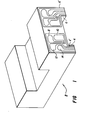
- an air bearing slider element 2 which may be made from ceramic or other non-magnetic material.
- the slider element 2 is provided with two rails 4, 6 extending respectively along the bottom edges of the slider element 2 parallel to the principal longitudinal axis thereof.
- the thin film transducer head of the present invention is disposed on the vertical surfaces 4', 6' of the rail portions 4, 6.
- the general dimensions of the slider element 2 are as follows.
- the overall height is about 1.92mm, top-to-bottom; the width is about 3.76mm.
- the rail portions 4, 5 are about 2.987mm, center-to-center, while the rail height and width are about 0.175m and 0.57mm, respectively.
- connection pads 8, 10, 12 and 14 are provided for connecting the thin film read-write transducer head to appropriate circuits for achieving the reading and writing functions.
- connection pads 8, 10, 12 and 14 are provided for connecting the thin film read-write transducer head to appropriate circuits for achieving the reading and writing functions.
- the slider element 2 is designed to "fly" over the surface of the magnetic recording medium with the transducer head itself being vertically disposed with respect to the recording medium on the vertical surfaces 4' and 6' of the slider assembly rail portions 4 and 6.
- a bottom yoke 20 is mounted on the vertical surface 4' of the rail member 4.
- a write conductor 22 is insulatingly mounted on the bottom yoke 20, with a top yoke 24 over the write conductor 22.
- the bottom yoke 20 is a continuous planar sheet of magnetic material which may be Permalloy (RTM) and which extends almost completely over the vertical surface 4' of the rail portion 4.
- the write conductor 22 is a U-shaped member of electrically conductive material.
- the top yoke 24 is disposed over the write conductor 22 within its U-shaped portions 22', 22" and over the horizontal portion 22"' which connects and is integral with the leg portions 22' and 22".
- the top yoke 24 may be described as being “comma” shaped since it actually comprises an oblong shaped portion 24' with a downwardly extending tail portion 24" which is angled with respect to the longitudinal axis of the connecting leg portion 22'" of the write conductor 22. It will be appreciated that in this view, only the elements constituting the inductively writing head portion of the transducer head have been shown for the sake of clarity in explaining the structure and the orientation of the transducer head and the structures shown in Figure 3.
- the complete head structure is shown in section as viewed from the side at 90 degrees with respect to the vertical surface 4' of the rail portion 4. Also shown is the disposition of the transducer head structure with respect to the surface of the recording medium 26 as the slider 2 flies over this surface.
- the thin film structures shown in section in Figure 3 are formed by thin film deposition and etching techniques utilizing the photoresist masking and sputtering procedures well known in the art of thin film fabrication.
- the slider including rail ports 4 and 6 integral therewith, may be made from ceramic material.
- the initial layer formed on the vertical surface 4' of the rail portion 4 is a layer 21 of aluminium oxide over which is formed the bottom yoke 20 of magnetic (i.e.
- the bottom yoke 20 is covered with an insulating layer 23 of silicon dioxide.
- a magnetoresistive film element 28 is then formed on the insulating layer 23.
- the magnetoresistive material may be nickel-cobalt or nickel- iron.
- a read conductor 30 is then formed on the insulating layer 23 and may be an electrically conductive material such as aluminium and copper which may be evaporated or sputtered onto the insulating layer 23 and on portions of the magnetoresistive element 28.
- An insulating layer 23' of silicon dioxide is then formed over the read conductor 30.
- the write conductor 22 is formed on the insulating layer 23'. Again, the write conductor 22 may be a composition of evaporated or sputtered aluminium and copper.
- the shape of the write conductor in cross section is that of a trapezoid.
- a further insulating coating or film 23" of silicon dioxide is then formed over the write conductor 22.
- the final operating element of the complete read-write transducer head is then formed of magnetic material (Permalloy) to provide and comprise the top yoke 24 which is disposed on the insulating layer 23".
- the final coating 32 is for protective purposes and may be aluminium oxide.
- All of the various layers described are of substantially uniform thickness. Typical thicknesses of these may be as follows.
- the insulating layers 23, 23' and 23" may be from 1.3 to 0.1 microns thick.
- the write conductor may be from 3.0 to 0.1 microns in thickness.
- the thickness of the top yoke may be from 0.5 to 10.0 microns.
- the position of the thin film head relative to the air bearing surface of the slider rail 4 is determined in a final lapping process after the thin film structures just described have been completely fabricated.
- the distance between the thin film head relative to the air bearing surface is called the throat depth and in an inductive-write magnetoresistive-read head the throat depth is a measure of the height of the magnetoresistive element 28 and the position of the write conductor 22 with respect to the air bearing surface of the slider rail 4. It will be appreciated that control of the throat depth is critical for properly writing and reading. Since two heads are provided per slider, one on each rail, this redundancy can be used to increase the yield to the critical throat depth specification by displacing the two heads on a single slider relative to each other by some fraction of the throat depth specification.
- a typical displacement fraction is .5.
- a slider having a throat depth below the distribution mean one head will be within specification. If the throat depth is above the distribution mean, the other head will be within specification.
- the relative displacment of the two heads is designed into the photo masking utilized in fabricating the thin film structures of the head according to the present invention.
- the redundancy of two heads per slider can be used to improve yields for other process steps.
- the relative position of the read and write elements is controlled by the top yoke alignment to the barber pole or read conductor level.
- the top yoke geometry is similar to the barber pole (read conductor) geometry.
- the edges of the tail portion 24" of the top yoke 24 in the vicinity of the air-bearing surface of the slider rail 4 are parallel with the edge portions of the barber pole or read conductor gap structure.
- the barber pole structure of the read conductor 30 includes a gap in the cross-leg portion of the read conductor 30, the gap being at an acute angle (i.e., 30-60 degrees and preferably about 34 degrees) with respect to the longitudinal axis of the cross-leg portion of the read conductor 30.
- the tail portion 24" of the top yoke 24 is at substantially the same angle (i.e., 34 degrees) and overlies the barber pole and gap regions of the read conductor.
Landscapes
- Engineering & Computer Science (AREA)
- Manufacturing & Machinery (AREA)
- Magnetic Heads (AREA)
Applications Claiming Priority (2)
| Application Number | Priority Date | Filing Date | Title |
|---|---|---|---|
| US482654 | 1983-04-04 | ||
| US06/482,654 US4555740A (en) | 1983-04-04 | 1983-04-04 | Thin film transducer head for inductive recording and magnetoresistive reading |
Publications (3)
| Publication Number | Publication Date |
|---|---|
| EP0124293A2 true EP0124293A2 (de) | 1984-11-07 |
| EP0124293A3 EP0124293A3 (en) | 1985-12-18 |
| EP0124293B1 EP0124293B1 (de) | 1990-03-14 |
Family
ID=23916901
Family Applications (1)
| Application Number | Title | Priority Date | Filing Date |
|---|---|---|---|
| EP84302234A Expired EP0124293B1 (de) | 1983-04-04 | 1984-04-02 | Dünnschichtwandler für induktive Aufzeichnung und magnetoresistive Wiedergabe |
Country Status (4)
| Country | Link |
|---|---|
| US (1) | US4555740A (de) |
| EP (1) | EP0124293B1 (de) |
| JP (1) | JPS59193518A (de) |
| DE (1) | DE3481660D1 (de) |
Cited By (5)
| Publication number | Priority date | Publication date | Assignee | Title |
|---|---|---|---|---|
| GB2169434A (en) * | 1984-11-24 | 1986-07-09 | Magnetic Components Limited | Magnetoresistive sensors |
| GB2175735A (en) * | 1985-04-26 | 1986-12-03 | Sharp Kk | Thin film magnetic head |
| EP0211445A1 (de) * | 1985-08-15 | 1987-02-25 | International Business Machines Corporation | Zusammensetzung eines magnetoresistiven Lesewandlers |
| WO1989012294A1 (fr) * | 1988-05-30 | 1989-12-14 | Siemens Aktiengesellschaft | Tete magnetique a couche mince a attenuation elevee des pistes secondaires |
| EP0387364A1 (de) * | 1989-03-13 | 1990-09-19 | Siemens Aktiengesellschaft | Dünnfilm-Magnetkopfeinheit |
Families Citing this family (18)
| Publication number | Priority date | Publication date | Assignee | Title |
|---|---|---|---|---|
| US4731686A (en) * | 1984-03-21 | 1988-03-15 | Canon Denshi Kabushiki Kaisha | Magnetic head |
| US4644430A (en) * | 1984-08-27 | 1987-02-17 | Eastman Kodak Company | Slotted sensor in yoke-type magneto-resistive head |
| JP2564262B2 (ja) * | 1985-02-27 | 1996-12-18 | 株式会社日立製作所 | 磁気抵抗効果型ヘツド |
| JP2599380B2 (ja) * | 1987-02-17 | 1997-04-09 | ティーディーケイ株式会社 | 浮上型磁気ヘツド |
| US4967298A (en) * | 1987-02-17 | 1990-10-30 | Mowry Greg S | Magnetic head with magnetoresistive sensor, inductive write head, and shield |
| US5010025A (en) * | 1989-04-03 | 1991-04-23 | Grumman Aerospace Corporation | Method of making trench JFET integrated circuit elements |
| EP0519182B1 (de) * | 1991-04-22 | 1997-02-12 | Sharp Kabushiki Kaisha | Kombinierter Dünnfilmmagnetkopf |
| JP2768372B2 (ja) * | 1992-04-20 | 1998-06-25 | 日本電気株式会社 | 複合型薄膜磁気ヘッド |
| US5621595A (en) * | 1992-10-20 | 1997-04-15 | Cohen; Uri | Pinched-gap magnetic recording thin film head |
| US5945007A (en) * | 1992-10-20 | 1999-08-31 | Cohen; Uri | Method for etching gap-vias in a magnetic thin film head and product |
| US5420736A (en) * | 1994-04-15 | 1995-05-30 | International Business Machines Corporation | MR read transducer with thermal noise cancellation |
| SG34292A1 (en) * | 1994-12-30 | 1996-12-06 | Ibm | Read/write magnetoresistive (MR) head with sunken components |
| JPH09167315A (ja) * | 1995-12-15 | 1997-06-24 | Hitachi Ltd | 録再分離型薄膜磁気ヘッド |
| US5768070A (en) | 1997-05-14 | 1998-06-16 | International Business Machines Corporation | Horizontal thin film write, MR read head |
| US6985330B2 (en) * | 2003-07-28 | 2006-01-10 | Hitachi Global Technologies Netherlands B.V. | High efficiency side-by-side thin film head utilizing canted shield yokes |
| US7889458B2 (en) * | 2006-11-13 | 2011-02-15 | Hitachi Global Storage Technologies Netherlands B.V. | Write head with self-cross biased pole for high speed magnetic recording |
| US20090010046A1 (en) * | 2007-06-28 | 2009-01-08 | Krishnakumar Mani | magnetic memory device with non-rectangular cross section current carrying conductors |
| US10950264B2 (en) * | 2019-06-26 | 2021-03-16 | Seagate Technology Llc | Transducer positions for dual actuator data storage devices |
Family Cites Families (8)
| Publication number | Priority date | Publication date | Assignee | Title |
|---|---|---|---|---|
| US3814863A (en) * | 1972-10-11 | 1974-06-04 | Ibm | Internally biased magnetoresistive magnetic transducer |
| US3813692A (en) * | 1972-10-11 | 1974-05-28 | Ibm | Internally biased magnetoresistive magnetic transducer |
| US3887945A (en) * | 1973-12-12 | 1975-06-03 | Ibm | Head assembly for recording and reading, employing inductive and magnetoresistive elements |
| US4001890A (en) * | 1974-08-05 | 1977-01-04 | Honeywell Information Systems, Inc. | Double chip flying head |
| US4255772A (en) * | 1979-06-29 | 1981-03-10 | International Business Machines Corporation | Read/write magnetic head assembly with magnetoresistive sensor |
| JPS5654629A (en) * | 1979-10-08 | 1981-05-14 | Hitachi Ltd | Compound thin-film magnetic head |
| JPS58166527A (ja) * | 1982-03-29 | 1983-10-01 | Nec Corp | 磁気抵抗効果ヘツド |
| US4504880A (en) * | 1982-08-09 | 1985-03-12 | International Business Machines Corporation | Integrated magnetic recording head assembly including an inductive write subassembly and a magnetoresistive read subassembly |
-
1983
- 1983-04-04 US US06/482,654 patent/US4555740A/en not_active Expired - Lifetime
-
1984
- 1984-04-02 EP EP84302234A patent/EP0124293B1/de not_active Expired
- 1984-04-02 DE DE8484302234T patent/DE3481660D1/de not_active Expired - Lifetime
- 1984-04-04 JP JP59067299A patent/JPS59193518A/ja active Granted
Cited By (8)
| Publication number | Priority date | Publication date | Assignee | Title |
|---|---|---|---|---|
| GB2169434A (en) * | 1984-11-24 | 1986-07-09 | Magnetic Components Limited | Magnetoresistive sensors |
| GB2169434B (en) * | 1984-11-24 | 1989-09-20 | Magnetic Components Limited | Magnetoresistive sensors |
| GB2175735A (en) * | 1985-04-26 | 1986-12-03 | Sharp Kk | Thin film magnetic head |
| US4789910A (en) * | 1985-04-26 | 1988-12-06 | Sharp Kabushiki Kaisha | Thin film magnetic head with an application type silicon dioxide film |
| GB2175735B (en) * | 1985-04-26 | 1989-06-28 | Sharp Kk | Thin film magnetic head |
| EP0211445A1 (de) * | 1985-08-15 | 1987-02-25 | International Business Machines Corporation | Zusammensetzung eines magnetoresistiven Lesewandlers |
| WO1989012294A1 (fr) * | 1988-05-30 | 1989-12-14 | Siemens Aktiengesellschaft | Tete magnetique a couche mince a attenuation elevee des pistes secondaires |
| EP0387364A1 (de) * | 1989-03-13 | 1990-09-19 | Siemens Aktiengesellschaft | Dünnfilm-Magnetkopfeinheit |
Also Published As
| Publication number | Publication date |
|---|---|
| DE3481660D1 (de) | 1990-04-19 |
| EP0124293A3 (en) | 1985-12-18 |
| EP0124293B1 (de) | 1990-03-14 |
| JPS59193518A (ja) | 1984-11-02 |
| US4555740A (en) | 1985-11-26 |
| JPH0475570B2 (de) | 1992-12-01 |
Similar Documents
| Publication | Publication Date | Title |
|---|---|---|
| EP0124293B1 (de) | Dünnschichtwandler für induktive Aufzeichnung und magnetoresistive Wiedergabe | |
| US6496329B2 (en) | Highly aligned thin film tape head | |
| EP0558195B1 (de) | Dünnschichtmagnetkopf | |
| US5296993A (en) | Magnetic head with magnetic substrate and an enhanced poletip thereon | |
| EP0100841B1 (de) | Integrierter Magnetwandlerkopfzusammenbau mit induktiver Schreibvorrichtung und magnetoresistiver Lesevorrichtung | |
| US4219855A (en) | Thin film magnetic head | |
| JP2670341B2 (ja) | 薄膜磁気ヘッド | |
| US6198607B1 (en) | Contact planar magnetoresistive head | |
| US5241439A (en) | Combined read/write thin film magnetic head with two pairs of flux guides | |
| JPH0855311A (ja) | オフ・トラック性能を改善するための一体的磁気抵抗ヘッド | |
| US5669133A (en) | Method of making a magnetoresistive sensor | |
| US7414816B2 (en) | Planar magnetic thin film head | |
| US5373624A (en) | Leading edge undershoot elimination in thin film heads | |
| US5694276A (en) | Shielded magnetic head having an inductive coil with low mutual inductance | |
| JP4081937B2 (ja) | 回転型磁気ヘッド装置の製造方法 | |
| US6134078A (en) | High sensitivity, low distortion yoke-type magnetoresistive head | |
| JPH11213332A (ja) | 薄膜磁気ヘッド及び磁気ディスク装置 | |
| JPS635803B2 (de) | ||
| JPS59151334A (ja) | 磁気ヘツド | |
| KR100234186B1 (ko) | 이중 갭을 가지는 평면형 조합 자기 저항 독출/서입 헤드 | |
| EP0408808A1 (de) | Magnetwandlerkopfstruktur | |
| JPH07153022A (ja) | 薄膜磁気ヘッド | |
| JPH06139524A (ja) | 磁気抵抗効果型ヘッドおよびその製造方法 | |
| JPS61142517A (ja) | 薄膜磁気ヘツドの製造方法 | |
| JPH05120638A (ja) | 磁気抵抗効果型薄膜磁気ヘツド |
Legal Events
| Date | Code | Title | Description |
|---|---|---|---|
| PUAI | Public reference made under article 153(3) epc to a published international application that has entered the european phase |
Free format text: ORIGINAL CODE: 0009012 |
|
| 17P | Request for examination filed |
Effective date: 19840424 |
|
| AK | Designated contracting states |
Designated state(s): DE FR GB |
|
| PUAL | Search report despatched |
Free format text: ORIGINAL CODE: 0009013 |
|
| AK | Designated contracting states |
Designated state(s): DE FR GB |
|
| 17Q | First examination report despatched |
Effective date: 19880518 |
|
| GRAA | (expected) grant |
Free format text: ORIGINAL CODE: 0009210 |
|
| AK | Designated contracting states |
Kind code of ref document: B1 Designated state(s): DE FR GB |
|
| REF | Corresponds to: |
Ref document number: 3481660 Country of ref document: DE Date of ref document: 19900419 |
|
| ET | Fr: translation filed | ||
| PLBE | No opposition filed within time limit |
Free format text: ORIGINAL CODE: 0009261 |
|
| STAA | Information on the status of an ep patent application or granted ep patent |
Free format text: STATUS: NO OPPOSITION FILED WITHIN TIME LIMIT |
|
| 26N | No opposition filed | ||
| REG | Reference to a national code |
Ref country code: GB Ref legal event code: 732E |
|
| REG | Reference to a national code |
Ref country code: FR Ref legal event code: TP |
|
| REG | Reference to a national code |
Ref country code: GB Ref legal event code: IF02 |
|
| PGFP | Annual fee paid to national office [announced via postgrant information from national office to epo] |
Ref country code: GB Payment date: 20030326 Year of fee payment: 20 |
|
| PGFP | Annual fee paid to national office [announced via postgrant information from national office to epo] |
Ref country code: FR Payment date: 20030418 Year of fee payment: 20 |
|
| PGFP | Annual fee paid to national office [announced via postgrant information from national office to epo] |
Ref country code: DE Payment date: 20030430 Year of fee payment: 20 |
|
| PG25 | Lapsed in a contracting state [announced via postgrant information from national office to epo] |
Ref country code: GB Free format text: LAPSE BECAUSE OF EXPIRATION OF PROTECTION Effective date: 20040401 |
|
| REG | Reference to a national code |
Ref country code: GB Ref legal event code: PE20 |