EP0123664B1 - Steuerungssystem mit einer, einer veränderlichen Kraft untergeordneten Handsteuerung - Google Patents
Steuerungssystem mit einer, einer veränderlichen Kraft untergeordneten Handsteuerung Download PDFInfo
- Publication number
- EP0123664B1 EP0123664B1 EP84850126A EP84850126A EP0123664B1 EP 0123664 B1 EP0123664 B1 EP 0123664B1 EP 84850126 A EP84850126 A EP 84850126A EP 84850126 A EP84850126 A EP 84850126A EP 0123664 B1 EP0123664 B1 EP 0123664B1
- Authority
- EP
- European Patent Office
- Prior art keywords
- magnitude
- displacement
- unit
- output
- positions
- Prior art date
- Legal status (The legal status is an assumption and is not a legal conclusion. Google has not performed a legal analysis and makes no representation as to the accuracy of the status listed.)
- Expired
Links
Images


Classifications
-
- B—PERFORMING OPERATIONS; TRANSPORTING
- B64—AIRCRAFT; AVIATION; COSMONAUTICS
- B64C—AEROPLANES; HELICOPTERS
- B64C13/00—Control systems or transmitting systems for actuating flying-control surfaces, lift-increasing flaps, air brakes, or spoilers
- B64C13/24—Transmitting means
- B64C13/38—Transmitting means with power amplification
- B64C13/50—Transmitting means with power amplification using electrical energy
- B64C13/507—Transmitting means with power amplification using electrical energy with artificial feel
-
- G—PHYSICS
- G05—CONTROLLING; REGULATING
- G05D—SYSTEMS FOR CONTROLLING OR REGULATING NON-ELECTRIC VARIABLES
- G05D1/00—Control of position, course, altitude or attitude of land, water, air or space vehicles, e.g. using automatic pilots
- G05D1/0055—Control of position, course, altitude or attitude of land, water, air or space vehicles, e.g. using automatic pilots with safety arrangements
- G05D1/0061—Control of position, course, altitude or attitude of land, water, air or space vehicles, e.g. using automatic pilots with safety arrangements for transition from automatic pilot to manual pilot and vice versa
Definitions
- This invention relates to control systems that have a controlled device which is actuated in response to displacements of a manipulatable control unit and wherein the control unit is subjected to a bias that opposes its displacement to provide a simulated feedback or "feel" that facilitates precise control; and the invention is more particularly concerned with a method and apparatus for varying the bias upon the control unit in accordance with predetermined criteria, to provide a "feel" that facilitates both manoeuvering and trimming manipulations of the control unit.
- the system for pitch control of an aircraft can be taken as typical of the various types of control systems that involve the problems and requirements addressed by this invention.
- the biasing forces on the stick are generated by aerodynamic forces on the actuated surfaces to which it is linked, and the pilot thus becomes accustomed to interpreting stick forces as having a relationship to the forces that the control surfaces exert for changing the attitude of the aircraft.
- the stick biasing forces constitute a feedback that assists the pilot in controlling the aircraft.
- a biasing force is artificially imposed upon the stick or manipulatable control unit, to yieldingly oppose its displacement away from the neutral position and yieldingly urge it back toward that position.
- This force gives the pilot information about the amount of displacement that he is imparting to the stick, in effect synthesizing the natural feedback or "feel" of a directly connected control system.
- trim system With a conventional manually controllable trim system it is possible to obtain a rather accurately controlled small change in aircraft attitude, even with large stick deflections and load factors.
- the employment of the trim system at large stick displacements has marked disadvantages that are not acceptable for high performance aircraft.
- the trim system is controlled by a manually operable nose-up/nose-down reversing switch that requires special attention and manipulation. It tends to respond somewhat slowly. If the trim system is actuated during a manoeuver involving large displacement of the control stick, then upon return of the stick to its neutral position the aircraft will not return to the same flight attitude that existed before trimming.
- the general object of the present invention is to provide a method of so varying the bias upon the manipulatable control unit in a control system of the character described as to provide the stick or other manipulatable control unit with a biasing force that has a low gradient for conditions under which the stick is manipulated through relatively large manoeuvering dis- placments but a substantially higher gradient when the stick is manipulated through relatively small trimming displacements.
- manipulatable control unit is biased to its neutral or null position with a biasing force that is automatically varied to provide for the imposition upon the control unit of a low gradient biasing force at times when large, coarse displacements of the control unit are being made and to provide for imposition upon it of a relatively high gradient biasing force when small, trimming displacements are being made.
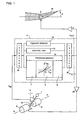
- a control system to which the method of this invention is applicable comprises a manipulatable control unit 1, which is here illustrated as an aircraft control stick.
- the control unit is supported for swinging displacement about an axis X-X, but it could as well be displaceable in translation.
- the control unit 1 will in any case have a neutral or null position, designated by R-R, towards and from which it is displaceable; and it may be displaceable away from the null position in only one direction or, as in the case of the aircraft stick here illustrated, in both directions.
- a signal transmitter 2 Connected to the control unit 1 is a signal transmitter 2 that generates an input which can be in analog form, as a steady signal of varying magnitude, or can be in digital form.
- Digital signals are generated at regular intervals, typically at a frequency of 100 Hz.
- the input has a magnitude 6IN that unambiguously corresponds to the existing position of displacement of the control unit 1.
- the magnitude 5IN can be considered to be the same thing as the input itself.
- each can be considered as identifying a position of the control unit, and the instantaneous magnitude of an analog input likewise signifies the then-existing position of that unit. It is here assumed that the input 6fN is negative for control unit positions at the stick-forward side of the null position and positive for positions at its stick-back side.
- the input from the transmitter 2 is fed to a computing unit 3 by which an actuating output Your is produced that may be in digital or analog form.
- the computing unit 3 is connected with an amplifier 4 from which the actuating output, as amplified, is in turn fed to a controlled device comprising an actuating instrumentality or servo mechanism 6 and a control surface 29 that is mechanically linked to the servo mechanism.
- the controlled device 6, 29 is actuated in response to the amplified output, to bring it to a position of displacement ⁇ that is dependent upon the position of displacement ⁇ IN of the control unit 1 and upon other criteria that may include flight conditions and load factors.
- the copending applications of the applicant, PE-A-0 123 665, filed 17.04.84 describes a method of controlling actuation of the controlled device in accordance with other criteria relating to the manner in which the control unit is manipulated.
- the computing unit 3 also produces an output F TQ that has, at each instant, a magnitude dependent upon the then-existing magnitude of the input signal ⁇ IN and also upon other criteria that are explained hereinafter.
- the output F ro after suitable amplification in an amplifier 28, is fed to a force generating unit 5 that is coupled to the control unit 1.
- the force generating unit 5 can be a torque motor that acts directly upon the axle 30 upon which the control stick is swingable, as schematically shown in Fig. 1.
- the force generating unit 5 imposes upon the control unit 1 a biasing force that yieldingly opposes its displacement away from its neutral position.
- the magnitude of that biasing force is at any instant proportional to the existing magnitude of the output F ro ; hence the magnitude of the output F To constitutes a demand value and signifies a biasing force.
- the computing unit 3 is preferably a data processor that is programmed for the algorithms needed for various control situations.
- the computing unit can comprise discrete components for working through the algorithms digitally or in analog form.
- the data processor comprises, in general, a central unit 31, a program memory 32 and a primary memory 33.
- Interfaces 34 and 35 respectively connected to the input and to the output of the data processor, match the input ⁇ IN to the data processor, match the actuation output your to the amplifier 4 and the servo unit 6, and match the output F TO to the amplifier 28 and the force generating unit 5.
- the data processor 3 is programmed to work through an algorithm, explained hereinafter, whereby, it determines, for each generated input signal ⁇ IN , the magnitude of the output signal F TQ that is to be produced in response to that input signal.
- the algorithm is stored in the program memory 32, and the box 9 in Fig. 1 designates a known type of instrumentality by which it is worked through.
- the input signals ⁇ IN may be subjected to other processing, as denoted by the boxes 7 and 8 in Fig. 1 for the purpose of producing the actuating signals your for the controlled device.
- control unit movement away from the null position is herein designated the "increase” direction, since such movement effects an increased deflection of the controlled device, and the opposite direction of control unit displacement is designated the “decrease” direction.
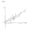
- Fig. 2 represents, for positive (stick back) displacements of the control stick, the relationships between input signals ⁇ IN and output signals F Ta .
- a first range of positions of displacement of the stick or control unit extending from the null or neutral point 0 to a position designated by ⁇ E , the system operates with a high gradient, that is, the biasing force rises steeply with displacement of the stick in the increase direction.
- a given increment or decrement of stick displacement is attended by a relatively large change in biasing force upon the stick, as denoted by the line segment OE, which represents a sequence of relationships between input signals ⁇ IN and output signals F TO .
- this high gradient facilitates accurate trimming in attitudes of substantially level flight.
- the point 6 H may be at the limit of displacement of the stick in the increase direction, or there may be a range of positions of the stick between its 6 H position and its limit position; and in the latter case the force gradient in that range, for both directions of control unit movement, may be different from the force gradient in the low gradient range ⁇ L - ⁇ H , and may be the same as, or different from, the gradient in the initial range O- ⁇ E .
- the line segment GE lies below the above discussed line segment LH, but its slope or gradient 2 is equal to-or at least generally similar to-the slope or gradient 1 of the segment LH, so that the line segments GE and LH are more or less parallel to one another.
- the respective changes in biasing force F TQ that are depicted by the respective line segments LH and GE will be equal-or substantially so-and relatively low; but for a given position of displacement of the stick, the corresponding point on the segment GE designates a lower biasing force on the stick than the corresponding point on the segment LH.
- T 1 designates a turning point at which the direction of stick displacement has been reversed from increase to decrease
- T 2 designates a turning point at which the direction of stick displacement has been reversed from decrease to increase.
- the slope 3 of the line segment y 3 is on the order of the slope 4 of the line segments OE and EL, which is to say that it represents a relatively high or steep gradient whereby a given increment or decrement of control stick displacement is attended by a relatively large increase or decrease in the biasing force upon the control stick.
- the line y 3 in Fig. 2 is one of a set of lines which can be visualized as drawn across the segments LH and GE to represent relationships of input to output signals after each of various turning points, each line of that set having a slope or gradient equal to-or substantially equal to-that of the illustrated line y 3 .
- the line segment EL is in effect a member of this set, as is the line segment GH.
- the several line segments EL, LH, HG and GE can be regarded as defining a belt-like modulation zone ELHGE wherein output signals F TO are dependent not only upon their related input signals ⁇ IN but also upon the manner in which the stick had been manipulated immediately before each output signal was produced.
- output signals F TO are dependent not only upon their related input signals ⁇ IN but also upon the manner in which the stick had been manipulated immediately before each output signal was produced.
- biasing force will of course increase as the stick is moved in the increase direction and decrease as it is moved in the decrease direction, but the rate of such increase or decrease will depend upon whether the pilot is making a manoeuvering displacement of the stick or a trimming displacement of it.
- These changes in biasing force are brought about by operation of the torque motor 5 as the stick is being displaced, to provide, at every instant, the biasing force signified by the then-current output signal F TQ .
- the output signal produced in response to every input signal in the range between 6 E and 6 H can be visualized as lying in the modulation zone ELHGE or on one of the segments that bound it.
- each of the several line segments OE, EL, LH, GE and y 3 may be either rectilinear or curvilinear, that is, it may have either a constant slope or gradient or one that increases in a non-uniform manner. Also, since the segments LH and GE need not be exactly parallel, the modulation zone ELHGE may be either wider or narrower at its top than at its bottom.
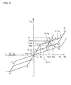
- FIG. 3 is a diagram for an aircraft pitch control system having rectilinear sequences of input signal to output signal relationships and having a modulation zone E'L'H'G'E' corresponding to the modulation zone for stick-back positions shown in Fig. 2 and a second generally similar zone A'B'D'C'A' for forward stick positions.
- the stick-forward zone A'B'D'C'A' is limited to a smaller range of stick positions than the stick-back zone E'L'H'G'E'.
- the diagram is in other respects the same for both sides of the neutral point O.
- the line segment OE' in Fig. 3 represents a first sequence of relationships between input signal magnitudes and output signal magnitudes that is defined and stored in the memory of the system.
- the sequence may be in the form of discrete values, or it can have the form of a function that defines a continuum of values.
- the output magnitudes F TQ in this first sequence are related to respective input signals ⁇ IN that designate positions of the control unit 1 between its null position and a position 6 E that is spaced from the null position by a predetermined distance in the increase direction.
- the output signal magnitudes F TO in this first sequence have a gradient k 3 of increase in the increase direction relative to their related input signal magnitudes, which gradient, as explained above, is relatively high or steep.
- the line segment G'E' represents a second sequence of relationships between input and output signal magnitudes, likewise stored in the system memory either as discrete values or as a function.
- the output signals F TQ of this second sequence are related to respective input signals ⁇ IN that designate positions of the control unit 1 between its ⁇ E position and a predetermined position 6 G that is spaced a substantial distance beyond ⁇ E in the increase direction.
- the output signal magnitudes in this second sequence have a second gradient k 1 of increase in the increase direction, said second gradient being substantially lower-that is, less steep-than the gradient k 3 .
- the line segment L'H' represents a third sequence of relationships between input and output signal magnitudes, likewise stored in the system memory either as discrete values or as a function.
- the output signals F TQ of this third sequence are related to respective input signals ⁇ IN that designate positions of the control unit 1 between a position 6 L that is intermediate its ⁇ E and 6 G positions and a position 6 H that is spaced beyond the 6 G position in the increase direction.
- the gradient of this third sequence is in this case equal to the gradient k 1 of the second sequence.
- the related output signal magnitude F TQ in the third sequence L'H' signifies a larger biasing force on the control unit 1 than the related output signal magnitude in the second sequence G'E'.
- the line y' 3 represents one of a set of "trim” sequences of relationships between input and output signal magnitudes, similarly defined and stored in the system memory.
- the output signal magnitudes in each "trim” sequence are related to respective input signals ⁇ IN that designate positions of the control unit 1 between its ⁇ E position and its 6 H position. All of the "trim” sequences have like gradients or slopes that are in this case equal to the relatively steep gradient k 3 of the first sequence.
- each "trim” sequence includes an output signal magnitude that is in the second sequence (G'E') and a different output signal magnitude that is in the third sequence (L'H'); and these two output signal magnitudes, which can be considered identifier magnitudes, can be visualized as the points at which the "trim" sequence line y' 3 (or any "trim” sequence line parallel to it) intersects the respective line segments G'E' and L'H'.
- sequences of input signal to output signal relationships that are generally similar to those described above for the stick-back positions are also defined and stored for the stick-forward range.
- information is temporarily stored that relates to the magnitude of each generated input signal and the magnitude of the output signal that was produced in response to it. Such information is employed in determining the magnitude of the output signal that is to be produced in response to the next generated input signal. After that next output signal is produced, the stored information can be discarded.
- the stored ⁇ IN /F TQ information designates a point which can be visualized as located between the line segments G'E' and L'H', then the stored information likewise designates a particular one of the "trim” sequences, since the ⁇ IN /F TQ relationships in each "trim” sequence (other than those for the identifier F TO magnitudes) are all unique to that particular sequence.
- the method proceeds on an initial assumption that the output signal to be produced in response to a newly generated input signal is to have the magnitude which is related to that input signal in the "trim" sequence identified by the stored information for the last preceding input signal.
- the method assumes that the stored information about the last preceding ⁇ IN / F TO signal pair designates a turning point, and the analysis continues on the assumption that the output signal magnitude for the newly generated input signal is to be determined from the particular "trim" sequence identified by the stored information.
- each "trim" sequence extends substantially to the left and to the right of the modulation area E'L'H'G'E', and therefore the presumptive output signal magnitude may fall within that area or may fall outside of it, either above it or below it. If the presumptive output signal magnitude falls within the area E'L'H'G'E', that is, if it is neither larger than the magnitude designated by T 1 nor smaller than the magnitude designated by T 2 , then the presumptive output signal magnitude is adopted as the actual output signal magnitude to be produced in response to the newly generated input signal.
- the point P in Fig. 3 illustrates a case in which the presumptive output signal magnitude falls outside the modulation zone E'L'H'G'E'.
- T is the point designated by the stored information
- the fact that the point P is outside (above) the modulation zone means that T, was not in fact a turning point, the stick has continued its movement in the increase direction, and the correct new output signal would be the one in the sequence L'H' that is related to the newly generated input signal.
- a presumptive output signal magnitude below the sequence G'E' would signify a continued movement of the stick in the decrease direction, and the actual output signal magnitude would be the one in the G'E' sequence that is related to the newly generated input signal.
- the initial assumption that the output signal for a newly generated input signal will be contained in an identifiable "trim” sequence applies to stick displacement within the initial range ⁇ 0 - ⁇ E , as well as to positions of displacement beyond that range, inasmuch as the first sequence, illustrated by segment OE', coincides with one of the "trim” sequences, and specifically comprises an extension of the "trim” sequence illustrated by segment E'L', which corresponds to the lower boundary of the modulation zone E'L'H'G'E'.
- the actual output signal magnitude will be the same as the presumptive output signal magnitude.
- the newly generated input signal ⁇ IN is compared with the input signal magnitude 6A for the forward limit of the stick- foward modulation zone A'B'D'C'A', to determine whether the newly generated ⁇ IN signal has a magnitude less than that compared 6A magnitude. If it has-signifying that the stick is at or forward of the 6A position-the output signal that is produced has the magnitude F A which is assigned to the 6A input signal magnitude, as illustrated by the box 24.
- This output signal magnitude corresponds to a limit value of rearward biasing force upon the stick that is in this case imposed upon the stick in all of its positions in a small range near and at the front limit of its displacement.
- information concerning this input signal and the output signal magnitude produced in response to it is preserved, as ⁇ INT and F TQT , respectively, for use in processing the next generated input signal.
- the magnitude of the newly generated input signal ⁇ IN is found not to be smaller than 6A it is next compared (box 11) with an input signal magnitude 6 H that corresponds to a stick position denoted by the point ⁇ H in Fig. 3, to determine whether the stick is in a small rearmost range of its positions, between the modulation zone E'L'H'G'E' and its most rearward position, in which range a relatively high stick force gradient is almost invariably desirable. If it is found to be in that rearmost range, then the output signal produced in response to the newly generated input signal will be assigned from a fifth sequence of input/output signal relationships, illustrated by line segment y' s in Fig. 3, and which has a gradient k 5 . This determination of the output signal is illustrated by the box 25. Again, information concerning the input and output signal magnitudes is preserved for use in processing the next input signal, as denoted by 6 INT and F TQT in box 25.
- the absolute value of that input signal is compared with an input signal magnitude 6 1 , to determine whether the new input signal corresponds to a stick position in a level flight range that is near the null point 0 and between the range of stick positions in which the respective modulation zones are applicable. If the stick position is found to be within that level flight range, and is at the positive side of the null point, the output signal generated in response to the newly generated input signal will be determined according to the sequence illustrated in Fig.
- the stored information 6 INT for the input signal and F TQT for the output signal will correspond to the input and output signal magnitudes for the null position of the stick, as also shown in box 26. If the stick is at the negative side of the null position, the output signal can be determined in the same way but will of course have a negative sign in conformity with the negative sign of the input signal, since segment OD' is the negative counterpart of segment OE'.
- the magnitude of the newly generated input signal is compared with zero, to determine whether it represents a stick-forward position or a stick-back position. If greater than zero, signifying a stick-back position (as is here assumed) the next stage of processing takes place as illustrated by the box 16; otherwise an analogous procedure is followed as illustrated by the box 15.
- point P in Fig. 3 designates the relationship between a newly generated input signal ⁇ IN and the presumptive output signal magnitude Fp that is assigned to that input signal. That presumptive value is assigned because the stored information for the preceding input signal corresponds to point T 1 , which identifies the "trim" sequence that includes the input-output relationship designated by point P.
- the related output signal magnitude F MIN in the third sequence would have the value denoted by point N
- the related output signal magnitude FMAx in the second sequence L'H'
- M denotes a maximum value for it.
- the determination of these maximum and minimum values for stick-back positions is illustrated by box 16, and the corresponding determination for stick-forward positions is illustrated by box 15.
- the presumptive output magnitude is compared with the maximum value F MAx just determined; and if it is greater than that compared magnitude, then, as illustrated by box 21, the actual output signal produced in response to the newly generated input signal has a magnitude equal to that maximum magnitude.
- F MAx the maximum value
- the presumptive output signal magnitude is compared with the just-determined minimum magnitude F MIN , as illustrated by box 18, and in this case if the assumed magnitude is less than the compared minimum magnitude, the produced output signal has that minimum magnitude.
- the torque motor 5 is solely responsible for the biasing force that opposes displacement of the manipulatable unit.
- a spring (not shown) for generating a basic biasing force acting upon the control unit. That basic force, together with the force generated by the torque motor 5, then provides the total desired force, which will of course be in accordance with the force diagram in Fig. 3.
- the basic force due to the spring is designated in Fig. 3 by the broken line F s .
- the demand value signified by each output signal as actually produced will take account of the component of biasing force that the spring contributes. Accordingly, the gradient of the output signals applied to the torque motor would have a lower slope, and in the case illustrated in Fig. 3 the line segments L'H' and G'E' could be horizontal and have a zero slope.
- a control system operating with a stick bias force control method of this invention based on rectilinear sequences such as are illustrated in Fig. 3, has been successfully tested under actual flight conditions.
- the force gradient for fine control manipulations was about twice that for coarse control.
- the modulation zone had a breadth of about 2° of stick displacement. The test demonstrated an advantageous influence upon control performances and control activity of the pilot, with an improved stick force feel, especially for trimming manipulations.
- Fig. 5 schematically illustrates apparatus for practicing the method of this invention with an analog computer.
- the input 6IN is a voltage having a value which at each instant signifies the existing position of the stick or control unit.
- the limit conditions depicted by the curve OE'L'H' in Fig. 3 are generated in the apparatus illustrated by box 42 in Fig. 5, irrespective of whether the stick is moving in the increase direction or in the decrease direction.
- the limit conditions depicted by the curve OE'G'H' are generated in a similar manner by the apparatus illustrated by box 43.
- the boxes inside it that are designated by k 3 and k respectively designate multiplication of the input magnitudes ⁇ IN by the gradient k 3 (corresponding to the slope of line segments OE' and E'L' in Fig.
- the apparatus illustrated in box 42 also produces a fixed voltage corresponding to an offset value which compensates for the fact that the line segment L'H', if extended, would not pass through the null position.
- the apparatus illustrated by box 43 and its cooperating summing junction SUM1 produces an output that corresponds to the output magnitude on the line segment OE', E'G' or G'H', as the case may be, that is related to the then-existing input magnitude; and it does this irrespective of whether the stick is moving in the increase or in the decrease direction.
- the determination of the direction in which the stick is being moved is made by apparatus illustrated by box 44, which can comprise a high-pass filter HP1 to which the input ⁇ IN is fed and which produces the derivative 5 of that input. That derivative is fed to a comparator COMP1 which produces a positive output if the stick is moving in the increase direction and a negative output if it is moving in the decrease direction.
- apparatus illustrated by box 44 can comprise a high-pass filter HP1 to which the input ⁇ IN is fed and which produces the derivative 5 of that input. That derivative is fed to a comparator COMP1 which produces a positive output if the stick is moving in the increase direction and a negative output if it is moving in the decrease direction.
- the output from the comparator COMP1 is fed to apparatus illustrated by box 45, which comprises inverters INV1, INV2 and INV3, a set-reset flip-flop MV1, and an EXCLUSIVE-OR gate GD1.
- the output of the flip-flop MV1 is fed to one input terminal of the EXCLUSIVE-OR gate GD1, where it is compared to the uninverted output of the comparator COMP1, which is connected with the other input terminal of that gate. If there is a change in the sign of the output from comparator COMP1, signifying a turning point or reversal of direction of stick movement, a short sign-shift pulse is issued by the EXCLUSIVE-OR gate GD1.
- the inverters INV1, INV2 and INV3 are so connected that a negative output from the comparator COMP1 sets the flip-flop MV1, so that it produces a "one" output, and a positive output from that comparator resets the flip-flop so that it produces a "zero” output.
- the circuit comprising the inverters and the flip-flop serves as a delay network, the delay in which determines the duration of the sign-shift pulse.
- the apparatus illustrated by box 46 comprises a pair of sample-and-hold circuits, one designated SH1 for the 6IN magnitude, the other designated SH2 for the F TO magnitude, which is fed back from the output of the signal processing apparatus. Both of these sample-and-hold circuits are rendered operative by a sign-shift pulse from the EXCLUSIVE-OR gate GD1.
- the information stored in the sample-and-hold circuits SH1 and SH2 identifies a point that is either in the modulation zone E'L'H'G'E' or on the short line sgement OE', and in either case it thus also defines a "trim" sequence line which passes through that point and has the slope k 3 .
- the related magnitude F TQ of the output on that defined line is given in terms of the stored input magnitude ⁇ INT and stored output magnitude F TOT by:
- An output corresponding to the existing input magnitude ⁇ IN multiplied by the slope or gradient characteristic k 3 is available from the apparatus designated by either of the boxes 42 or 43 and is applied to one input terminal of the summing junction SUM3.
- An input corresponding to the stored output magnitude F ToT from the sample-and-hold circuit SH2, is applied to another input terminal of the summing junction SUM3.
- From the sample-and-hold circuit SH1 an output corresponding to the stored input magnitude ⁇ INT is multiplied by the negative value of the slope characteristic k 3 , and the product of this multiplication is applied to the third terminal of the summing junction SUM3.
- the output from that summing junction thus corresponds to a presumptive value of the output magnitude F TO .
- the selection from among these possibilities is made by the apparatus denoted by box 47, which comprises two comparators COMP2 and COMP3 that receive inputs from the several summing junctions and have their respective output terminals connected with respective input terminals of an AND-gate GD2.
- the summing junctions SUM1, SUM2 and SUM3 also have their respective output terminals connected to respective input terminals 2, 3 and 1 of a function switch SW3 that is controlled by the AND-gate GD2.
- the comparators COMP2 and COMP3 are of the Schmitt trigger type, to prevent unnecessary function changes in the function switch SW3.
- the output of the summing junction SUM1 (which corresponds to the output magnitude on the "decrease” curve OE'G'H' that is related to the existing input ⁇ IN ) is fed to one input terminal of the comparator COMP3, and the output of the summing junction SUM2 (corresponding to the output magnitude on the "increase” curve OE'L'H' that is related to the existing input 6 1N ) is fed to one input terminal of the comparator COMP2.
- the other input terminal of each of those comparators COMP2, COMP3 is connected with the output terminal of the summing junction SUM3.
- comparator COMP2 If the input from summing junction SUM3 to comparator COMP2 is larger that the input to that comparator from summing junction SUM2, comparator COMP2 produces a "one” output, otherwise it produces a “zero” output. If the input from summing junction SUM3 to comparator COMP3 is smaller than the input to that comparator from summing junction SUM1, comparator COMP3 produces a "one” output, otherwise it produces a "zero” output.
- AND-gate GD2 With “zero" inputs to both of its input terminals, AND-gate GD2 produces a “zero” output and sets the function switch SW3 to either of its input terminals 1 or 0, both of which are connected to the output of summing junction SUM3, so that the produced output magnitude F TQ is the "trim" output generated at summing junction SUM3.
- the output from function switch SW3 will be taken either from its terminal 2 or its terminal 3, depending upon whether the output of comparator COMP1 is negative or positive.
- the output of that comparator is also fed to the function switch SW3 for control of it, so that with stick movement in the decrease direction the output f T ⁇ follows the curve OE'G'H' and with stick movement in the increase direction the output F T ⁇ follows the curve OE'L'H'.
- the biasing force applied to the control unit has a low gradient when that unit is moved through a substantially large continuous displacement in either direction or through a succession of small displacements that are all in the same direction, but has a high gradient that facilitates fine control when there has been a change in the direction of displacement of the control unit, and particularly during a small displacement immediately following such a change in direction.
- the operator can obtain more precise and suitable movements of the controlled device, and hence better control performance than was possible heretofore.
- the locally heightened force gradient, provided for by the "trim” sequences, is brought into effect in any position of the control unit within the range of positions to which the "trim” sequences apply.
- the method is easily put into practice, is not impaired by time dependent side effects, and reduces the risk of operator-induced oscillations.
Landscapes
- Engineering & Computer Science (AREA)
- Aviation & Aerospace Engineering (AREA)
- Automation & Control Theory (AREA)
- Radar, Positioning & Navigation (AREA)
- Remote Sensing (AREA)
- Physics & Mathematics (AREA)
- General Physics & Mathematics (AREA)
- Feedback Control In General (AREA)
- Mechanical Control Devices (AREA)
- Endoscopes (AREA)
- Prostheses (AREA)
- Control Of Position Or Direction (AREA)
Claims (9)
Priority Applications (1)
| Application Number | Priority Date | Filing Date | Title |
|---|---|---|---|
| AT84850126T ATE41068T1 (de) | 1983-04-18 | 1984-04-17 | Steuerungssystem mit einer, einer veraenderlichen kraft untergeordneten handsteuerung. |
Applications Claiming Priority (2)
| Application Number | Priority Date | Filing Date | Title |
|---|---|---|---|
| SE8302137 | 1983-04-18 | ||
| SE8302137A SE442852B (sv) | 1983-04-18 | 1983-04-18 | Forfarande och anordning vid styrsystem for att astadkomma forhojd momentgradient for sma manoverdonsrorelser |
Publications (3)
| Publication Number | Publication Date |
|---|---|
| EP0123664A2 EP0123664A2 (de) | 1984-10-31 |
| EP0123664A3 EP0123664A3 (en) | 1986-01-08 |
| EP0123664B1 true EP0123664B1 (de) | 1989-03-01 |
Family
ID=20350832
Family Applications (1)
| Application Number | Title | Priority Date | Filing Date |
|---|---|---|---|
| EP84850126A Expired EP0123664B1 (de) | 1983-04-18 | 1984-04-17 | Steuerungssystem mit einer, einer veränderlichen Kraft untergeordneten Handsteuerung |
Country Status (5)
| Country | Link |
|---|---|
| US (1) | US4580210A (de) |
| EP (1) | EP0123664B1 (de) |
| AT (1) | ATE41068T1 (de) |
| DE (1) | DE3476929D1 (de) |
| SE (1) | SE442852B (de) |
Families Citing this family (41)
| Publication number | Priority date | Publication date | Assignee | Title |
|---|---|---|---|---|
| JPS62122685A (ja) * | 1985-11-25 | 1987-06-03 | 双葉電子工業株式会社 | 模型飛行機等無線遠隔操縦装置におけるトリム制御装置 |
| DE3605088A1 (de) * | 1986-02-18 | 1987-11-05 | Bosch Gmbh Robert | Bedieneinrichtung |
| US4800721A (en) | 1987-02-13 | 1989-01-31 | Caterpillar Inc. | Force feedback lever |
| FR2647922B1 (fr) * | 1989-05-31 | 1993-12-31 | Sextant Avionique | Dispositif de commande electromecanique utilisable pour le pilotage d'un vehicule |
| US5029778A (en) * | 1989-09-11 | 1991-07-09 | The Boeing Company | Throttle control system having real-time-computed thrust vs throttle position function |
| US5493497A (en) * | 1992-06-03 | 1996-02-20 | The Boeing Company | Multiaxis redundant fly-by-wire primary flight control system |
| US5588800B1 (en) * | 1994-05-31 | 2000-12-19 | Mcdonell Douglas Helicopter Co | Blade vortex interaction noise reduction techniques for a rotorcraft |
| US5489830A (en) * | 1994-09-09 | 1996-02-06 | Mcdonnell Douglas Corporation | Control system with loadfeel and backdrive |
| US5694014A (en) * | 1995-08-22 | 1997-12-02 | Honeywell Inc. | Active hand controller redundancy and architecture |
| US5791875A (en) * | 1996-09-10 | 1998-08-11 | Mcdonnell Douglas Helicopter Co. | Tip vortex reduction system |
| US5813625A (en) * | 1996-10-09 | 1998-09-29 | Mcdonnell Douglas Helicopter Company | Active blowing system for rotorcraft vortex interaction noise reduction |
| US5938404A (en) * | 1997-06-05 | 1999-08-17 | Mcdonnell Douglas Helicopter Company | Oscillating air jets on aerodynamic surfaces |
| US6092990A (en) * | 1997-06-05 | 2000-07-25 | Mcdonnell Douglas Helicopter Company | Oscillating air jets for helicopter rotor aerodynamic control and BVI noise reduction |
| US6543719B1 (en) | 1997-06-05 | 2003-04-08 | Mcdonnell Douglas Helicopter Co. | Oscillating air jets for implementing blade variable twist, enhancing engine and blade efficiency, and reducing drag, vibration, download and ir signature |
| US6234751B1 (en) | 1997-06-05 | 2001-05-22 | Mcdonnell Douglas Helicopter Co. | Oscillating air jets for reducing HSI noise |
| US6478541B1 (en) | 2001-08-16 | 2002-11-12 | The Boeing Company | Tapered/segmented flaps for rotor blade-vortex interaction (BVI) noise and vibration reduction |
| JP4160843B2 (ja) * | 2003-02-24 | 2008-10-08 | アルプス電気株式会社 | 力覚付与型入力装置 |
| US20050245789A1 (en) | 2003-04-01 | 2005-11-03 | Boston Scientific Scimed, Inc. | Fluid manifold for endoscope system |
| US7591783B2 (en) | 2003-04-01 | 2009-09-22 | Boston Scientific Scimed, Inc. | Articulation joint for video endoscope |
| US20040199052A1 (en) | 2003-04-01 | 2004-10-07 | Scimed Life Systems, Inc. | Endoscopic imaging system |
| US8118732B2 (en) | 2003-04-01 | 2012-02-21 | Boston Scientific Scimed, Inc. | Force feedback control system for video endoscope |
| US7578786B2 (en) | 2003-04-01 | 2009-08-25 | Boston Scientific Scimed, Inc. | Video endoscope |
| FR2874204B1 (fr) * | 2004-08-13 | 2007-12-14 | Airbus France Sas | Systeme de commande de vol electriques pour les gouvernes de profondeur d'un aeronef |
| US8083671B2 (en) | 2004-09-30 | 2011-12-27 | Boston Scientific Scimed, Inc. | Fluid delivery system for use with an endoscope |
| US7479106B2 (en) | 2004-09-30 | 2009-01-20 | Boston Scientific Scimed, Inc. | Automated control of irrigation and aspiration in a single-use endoscope |
| US20060069305A1 (en) * | 2004-09-30 | 2006-03-30 | Boston Scientific Scimed, Inc. | Device with enhanced indication of use and prevention of re-use |
| CA2581079A1 (en) | 2004-09-30 | 2006-04-13 | Boston Scientific Scimed, Inc. | Multi-functional endoscopic system for use in electrosurgical applications |
| US7597662B2 (en) | 2004-09-30 | 2009-10-06 | Boston Scientific Scimed, Inc. | Multi-fluid delivery system |
| WO2006039511A2 (en) | 2004-09-30 | 2006-04-13 | Boston Scientific Scimed, Inc. | System and method of obstruction removal |
| AU2005291952A1 (en) | 2004-09-30 | 2006-04-13 | Boston Scientific Limited | Adapter for use with digital imaging medical device |
| US7241263B2 (en) | 2004-09-30 | 2007-07-10 | Scimed Life Systems, Inc. | Selectively rotatable shaft coupler |
| US8097003B2 (en) * | 2005-05-13 | 2012-01-17 | Boston Scientific Scimed, Inc. | Endoscopic apparatus with integrated variceal ligation device |
| US7846107B2 (en) | 2005-05-13 | 2010-12-07 | Boston Scientific Scimed, Inc. | Endoscopic apparatus with integrated multiple biopsy device |
| FR2888009B1 (fr) * | 2005-06-30 | 2007-09-07 | Dassault Aviat | Dispositif de commande comportant deux manches couples pour permettre de placer des organes commandes dans des positions souhaitees |
| US8052597B2 (en) | 2005-08-30 | 2011-11-08 | Boston Scientific Scimed, Inc. | Method for forming an endoscope articulation joint |
| US7967759B2 (en) | 2006-01-19 | 2011-06-28 | Boston Scientific Scimed, Inc. | Endoscopic system with integrated patient respiratory status indicator |
| US8888684B2 (en) | 2006-03-27 | 2014-11-18 | Boston Scientific Scimed, Inc. | Medical devices with local drug delivery capabilities |
| US7955255B2 (en) | 2006-04-20 | 2011-06-07 | Boston Scientific Scimed, Inc. | Imaging assembly with transparent distal cap |
| US8202265B2 (en) | 2006-04-20 | 2012-06-19 | Boston Scientific Scimed, Inc. | Multiple lumen assembly for use in endoscopes or other medical devices |
| FR2987468B1 (fr) | 2012-02-23 | 2014-12-12 | Sagem Defense Securite | Dispositif pour generer des efforts de rappel pour des manches tels que des manches d'aeronefs |
| FR3030449B1 (fr) * | 2014-12-19 | 2017-11-24 | Airbus Operations Sas | Procede et systeme de commande de direction pour un aeronef |
Family Cites Families (9)
| Publication number | Priority date | Publication date | Assignee | Title |
|---|---|---|---|---|
| US4106728A (en) * | 1977-01-17 | 1978-08-15 | Sperry Rand Corporation | Fail safe force feel system |
| US4078749A (en) * | 1977-05-24 | 1978-03-14 | United Technologies Corporation | Helicopter stick force augmentation null offset compensation |
| DE2807902C2 (de) * | 1978-02-24 | 1980-04-30 | Messerschmitt-Boelkow-Blohm Gmbh, 8000 Muenchen | Steuereinrichtung mit aktiver Kraft rückführung |
| US4294162A (en) * | 1979-07-23 | 1981-10-13 | United Technologies Corporation | Force feel actuator fault detection with directional threshold |
| US4313165A (en) * | 1979-10-23 | 1982-01-26 | United Technologies Corporation | Force feel actuator with limited proportional/integral error feedback |
| US4382281A (en) * | 1980-08-08 | 1983-05-03 | United Technologies Corporation | Helicopter force feel actuator automatic static null compensation |
| US4417308A (en) * | 1981-03-30 | 1983-11-22 | United Technologies Corporation | Dual inner loop fault inhibit of aircraft outer loop |
| US4527242A (en) * | 1982-06-28 | 1985-07-02 | Rockwell International Corporation | Automatic flight control pilot assist system |
| US4477043A (en) * | 1982-12-15 | 1984-10-16 | The United States Of America As Represented By The Secretary Of The Air Force | Biodynamic resistant control stick |
-
1983
- 1983-04-18 SE SE8302137A patent/SE442852B/sv not_active IP Right Cessation
-
1984
- 1984-04-17 EP EP84850126A patent/EP0123664B1/de not_active Expired
- 1984-04-17 DE DE8484850126T patent/DE3476929D1/de not_active Expired
- 1984-04-17 US US06/601,260 patent/US4580210A/en not_active Expired - Lifetime
- 1984-04-17 AT AT84850126T patent/ATE41068T1/de not_active IP Right Cessation
Also Published As
| Publication number | Publication date |
|---|---|
| EP0123664A2 (de) | 1984-10-31 |
| EP0123664A3 (en) | 1986-01-08 |
| SE8302137L (sv) | 1984-10-19 |
| SE442852B (sv) | 1986-02-03 |
| US4580210A (en) | 1986-04-01 |
| SE8302137D0 (sv) | 1983-04-18 |
| ATE41068T1 (de) | 1989-03-15 |
| DE3476929D1 (en) | 1989-04-06 |
Similar Documents
| Publication | Publication Date | Title |
|---|---|---|
| EP0123664B1 (de) | Steuerungssystem mit einer, einer veränderlichen Kraft untergeordneten Handsteuerung | |
| DE2335855C2 (de) | Automatisches Flugsteuersystem | |
| EP0031619B1 (de) | System zum Steuern des vertikalen Flugweges eines Flugzeuges | |
| EP0034874B1 (de) | Steuersystem für die Flugzeuglandung | |
| US4114842A (en) | Acceleration limited preselect altitude capture and control | |
| US3446946A (en) | Power-moment self-adaptive control system | |
| US3652835A (en) | Aircraft glide slope coupler system | |
| US4709336A (en) | Descent flight path control for aircraft | |
| EP0054553B1 (de) | Steuersignal für den abfangübergangsbereich eines flugzeuges | |
| US3333795A (en) | Flare computer | |
| US4758958A (en) | Method and apparatus for trimming and stabilizing an aircraft | |
| US3327973A (en) | Automatic landing pitch axis control system for aircraft | |
| US5695156A (en) | Aircraft vertical position control system | |
| EP0224279B1 (de) | Vorrichtung und Verfahren zum Generieren von Steuerbefehlen für ein Flugzeug unter Verwendung einer Rückkopplung mit nichtlinearer Verstärkung | |
| CA1156746A (en) | Control system | |
| EP0078688B1 (de) | Geschwindigkeitssteuervorrichtung für Flugzeug | |
| EP0123665B1 (de) | Verfahren um in einem Steuersystem die Antwortgenauigkeit zu verändern | |
| US4312039A (en) | Transient free synchronization system | |
| EP0471395B1 (de) | Verfahren und Vorrichtung zur Überwachung des gesteuerten Befehls für ein Flugzeug mit Begrenzung von einem vorbestimmten Flugparameter | |
| US4609988A (en) | Automatic prediction and capture of a preselected altitude for aircraft | |
| EP0444541B1 (de) | Verfahren und Vorrichtung zu einem allmählichen Übergang zwischen einer kalibrierten Luftgeschwindigkeitssteuerung und einer Machzahlsteuerung eines Flugzeuges | |
| US4583030A (en) | Pitch/trim control | |
| SE450371B (sv) | Manoverkraftgradientsystem | |
| US3627238A (en) | Speed command generation system for vertical descent control | |
| US4150911A (en) | Control device for the laying of pipe in deep water |
Legal Events
| Date | Code | Title | Description |
|---|---|---|---|
| PUAI | Public reference made under article 153(3) epc to a published international application that has entered the european phase |
Free format text: ORIGINAL CODE: 0009012 |
|
| AK | Designated contracting states |
Designated state(s): AT CH DE FR GB IT LI |
|
| PUAL | Search report despatched |
Free format text: ORIGINAL CODE: 0009013 |
|
| AK | Designated contracting states |
Designated state(s): AT CH DE FR GB IT LI |
|
| 17P | Request for examination filed |
Effective date: 19860211 |
|
| 17Q | First examination report despatched |
Effective date: 19871009 |
|
| ITF | It: translation for a ep patent filed | ||
| GRAA | (expected) grant |
Free format text: ORIGINAL CODE: 0009210 |
|
| AK | Designated contracting states |
Kind code of ref document: B1 Designated state(s): AT CH DE FR GB IT LI |
|
| REF | Corresponds to: |
Ref document number: 41068 Country of ref document: AT Date of ref document: 19890315 Kind code of ref document: T |
|
| REF | Corresponds to: |
Ref document number: 3476929 Country of ref document: DE Date of ref document: 19890406 |
|
| ET | Fr: translation filed | ||
| PLBE | No opposition filed within time limit |
Free format text: ORIGINAL CODE: 0009261 |
|
| STAA | Information on the status of an ep patent application or granted ep patent |
Free format text: STATUS: NO OPPOSITION FILED WITHIN TIME LIMIT |
|
| 26N | No opposition filed | ||
| ITTA | It: last paid annual fee | ||
| PGFP | Annual fee paid to national office [announced via postgrant information from national office to epo] |
Ref country code: GB Payment date: 19980408 Year of fee payment: 15 |
|
| PGFP | Annual fee paid to national office [announced via postgrant information from national office to epo] |
Ref country code: FR Payment date: 19980409 Year of fee payment: 15 |
|
| PGFP | Annual fee paid to national office [announced via postgrant information from national office to epo] |
Ref country code: AT Payment date: 19980415 Year of fee payment: 15 |
|
| PGFP | Annual fee paid to national office [announced via postgrant information from national office to epo] |
Ref country code: DE Payment date: 19980424 Year of fee payment: 15 |
|
| PGFP | Annual fee paid to national office [announced via postgrant information from national office to epo] |
Ref country code: CH Payment date: 19980506 Year of fee payment: 15 |
|
| PG25 | Lapsed in a contracting state [announced via postgrant information from national office to epo] |
Ref country code: GB Free format text: LAPSE BECAUSE OF NON-PAYMENT OF DUE FEES Effective date: 19990417 Ref country code: AT Free format text: LAPSE BECAUSE OF NON-PAYMENT OF DUE FEES Effective date: 19990417 |
|
| PG25 | Lapsed in a contracting state [announced via postgrant information from national office to epo] |
Ref country code: LI Free format text: LAPSE BECAUSE OF NON-PAYMENT OF DUE FEES Effective date: 19990430 Ref country code: CH Free format text: LAPSE BECAUSE OF NON-PAYMENT OF DUE FEES Effective date: 19990430 |
|
| GBPC | Gb: european patent ceased through non-payment of renewal fee |
Effective date: 19990417 |
|
| REG | Reference to a national code |
Ref country code: CH Ref legal event code: PL |
|
| PG25 | Lapsed in a contracting state [announced via postgrant information from national office to epo] |
Ref country code: FR Free format text: LAPSE BECAUSE OF NON-PAYMENT OF DUE FEES Effective date: 19991231 |
|
| REG | Reference to a national code |
Ref country code: FR Ref legal event code: ST |
|
| PG25 | Lapsed in a contracting state [announced via postgrant information from national office to epo] |
Ref country code: DE Free format text: LAPSE BECAUSE OF NON-PAYMENT OF DUE FEES Effective date: 20000201 |