EP0123600A1 - Connecting tube having a ring clamped at its end - Google Patents
Connecting tube having a ring clamped at its end Download PDFInfo
- Publication number
- EP0123600A1 EP0123600A1 EP84400702A EP84400702A EP0123600A1 EP 0123600 A1 EP0123600 A1 EP 0123600A1 EP 84400702 A EP84400702 A EP 84400702A EP 84400702 A EP84400702 A EP 84400702A EP 0123600 A1 EP0123600 A1 EP 0123600A1
- Authority
- EP
- European Patent Office
- Prior art keywords
- ring
- tube
- groove
- mandrel
- deformation
- Prior art date
- Legal status (The legal status is an assumption and is not a legal conclusion. Google has not performed a legal analysis and makes no representation as to the accuracy of the status listed.)
- Granted
Links
Images


Classifications
-
- F—MECHANICAL ENGINEERING; LIGHTING; HEATING; WEAPONS; BLASTING
- F16—ENGINEERING ELEMENTS AND UNITS; GENERAL MEASURES FOR PRODUCING AND MAINTAINING EFFECTIVE FUNCTIONING OF MACHINES OR INSTALLATIONS; THERMAL INSULATION IN GENERAL
- F16L—PIPES; JOINTS OR FITTINGS FOR PIPES; SUPPORTS FOR PIPES, CABLES OR PROTECTIVE TUBING; MEANS FOR THERMAL INSULATION IN GENERAL
- F16L13/00—Non-disconnectible pipe-joints, e.g. soldered, adhesive or caulked joints
- F16L13/14—Non-disconnectible pipe-joints, e.g. soldered, adhesive or caulked joints made by plastically deforming the material of the pipe, e.g. by flanging, rolling
- F16L13/141—Non-disconnectible pipe-joints, e.g. soldered, adhesive or caulked joints made by plastically deforming the material of the pipe, e.g. by flanging, rolling by crimping or rolling from the outside
-
- B—PERFORMING OPERATIONS; TRANSPORTING
- B21—MECHANICAL METAL-WORKING WITHOUT ESSENTIALLY REMOVING MATERIAL; PUNCHING METAL
- B21D—WORKING OR PROCESSING OF SHEET METAL OR METAL TUBES, RODS OR PROFILES WITHOUT ESSENTIALLY REMOVING MATERIAL; PUNCHING METAL
- B21D39/00—Application of procedures in order to connect objects or parts, e.g. coating with sheet metal otherwise than by plating; Tube expanders
- B21D39/04—Application of procedures in order to connect objects or parts, e.g. coating with sheet metal otherwise than by plating; Tube expanders of tubes with tubes; of tubes with rods
-
- F—MECHANICAL ENGINEERING; LIGHTING; HEATING; WEAPONS; BLASTING
- F16—ENGINEERING ELEMENTS AND UNITS; GENERAL MEASURES FOR PRODUCING AND MAINTAINING EFFECTIVE FUNCTIONING OF MACHINES OR INSTALLATIONS; THERMAL INSULATION IN GENERAL
- F16L—PIPES; JOINTS OR FITTINGS FOR PIPES; SUPPORTS FOR PIPES, CABLES OR PROTECTIVE TUBING; MEANS FOR THERMAL INSULATION IN GENERAL
- F16L13/00—Non-disconnectible pipe-joints, e.g. soldered, adhesive or caulked joints
- F16L13/14—Non-disconnectible pipe-joints, e.g. soldered, adhesive or caulked joints made by plastically deforming the material of the pipe, e.g. by flanging, rolling
- F16L13/147—Non-disconnectible pipe-joints, e.g. soldered, adhesive or caulked joints made by plastically deforming the material of the pipe, e.g. by flanging, rolling by radially expanding the inner part
-
- F—MECHANICAL ENGINEERING; LIGHTING; HEATING; WEAPONS; BLASTING
- F16—ENGINEERING ELEMENTS AND UNITS; GENERAL MEASURES FOR PRODUCING AND MAINTAINING EFFECTIVE FUNCTIONING OF MACHINES OR INSTALLATIONS; THERMAL INSULATION IN GENERAL
- F16L—PIPES; JOINTS OR FITTINGS FOR PIPES; SUPPORTS FOR PIPES, CABLES OR PROTECTIVE TUBING; MEANS FOR THERMAL INSULATION IN GENERAL
- F16L19/00—Joints in which sealing surfaces are pressed together by means of a member, e.g. a swivel nut, screwed on or into one of the joint parts
- F16L19/02—Pipe ends provided with collars or flanges, integral with the pipe or not, pressed together by a screwed member
- F16L19/025—Pipe ends provided with collars or flanges, integral with the pipe or not, pressed together by a screwed member the pipe ends having integral collars or flanges
- F16L19/028—Pipe ends provided with collars or flanges, integral with the pipe or not, pressed together by a screwed member the pipe ends having integral collars or flanges the collars or flanges being obtained by deformation of the pipe wall
-
- Y—GENERAL TAGGING OF NEW TECHNOLOGICAL DEVELOPMENTS; GENERAL TAGGING OF CROSS-SECTIONAL TECHNOLOGIES SPANNING OVER SEVERAL SECTIONS OF THE IPC; TECHNICAL SUBJECTS COVERED BY FORMER USPC CROSS-REFERENCE ART COLLECTIONS [XRACs] AND DIGESTS
- Y10—TECHNICAL SUBJECTS COVERED BY FORMER USPC
- Y10T—TECHNICAL SUBJECTS COVERED BY FORMER US CLASSIFICATION
- Y10T29/00—Metal working
- Y10T29/49—Method of mechanical manufacture
- Y10T29/49826—Assembling or joining
- Y10T29/49908—Joining by deforming
- Y10T29/49915—Overedge assembling of seated part
- Y10T29/4992—Overedge assembling of seated part by flaring inserted cup or tube end
-
- Y—GENERAL TAGGING OF NEW TECHNOLOGICAL DEVELOPMENTS; GENERAL TAGGING OF CROSS-SECTIONAL TECHNOLOGIES SPANNING OVER SEVERAL SECTIONS OF THE IPC; TECHNICAL SUBJECTS COVERED BY FORMER USPC CROSS-REFERENCE ART COLLECTIONS [XRACs] AND DIGESTS
- Y10—TECHNICAL SUBJECTS COVERED BY FORMER USPC
- Y10T—TECHNICAL SUBJECTS COVERED BY FORMER US CLASSIFICATION
- Y10T29/00—Metal working
- Y10T29/49—Method of mechanical manufacture
- Y10T29/49826—Assembling or joining
- Y10T29/49908—Joining by deforming
- Y10T29/49938—Radially expanding part in cavity, aperture, or hollow body
- Y10T29/4994—Radially expanding internal tube
-
- Y—GENERAL TAGGING OF NEW TECHNOLOGICAL DEVELOPMENTS; GENERAL TAGGING OF CROSS-SECTIONAL TECHNOLOGIES SPANNING OVER SEVERAL SECTIONS OF THE IPC; TECHNICAL SUBJECTS COVERED BY FORMER USPC CROSS-REFERENCE ART COLLECTIONS [XRACs] AND DIGESTS
- Y10—TECHNICAL SUBJECTS COVERED BY FORMER USPC
- Y10T—TECHNICAL SUBJECTS COVERED BY FORMER US CLASSIFICATION
- Y10T29/00—Metal working
- Y10T29/53—Means to assemble or disassemble
- Y10T29/5367—Coupling to conduit
Definitions
- the invention relates to tube connections. It relates in particular to the connections of small diameter and / or thin-walled tubes, such as those used for the distribution of fuel in aircraft or automobile engines.
- an axially compressible mandrel is introduced into the tube, then using a suitable system, its circumference is extended at the level of the grooves of the ring, and the wall of the tube is thus radially stamped. direction of the bottom of the said gorges. Then after having carried out this deformation of the tube from the inside, the compression force is eliminated and the mandrel is removed.
- the tube remains anchored in its ring, and can then be connected in the usual way using a connector body and a nut screwing onto it.
- the most frequently used rings are relatively long and, to ensure sufficient anchoring, comprise two successive grooves defining a separation rib and an end rib.
- the deformation of the tube being limited, the presence in the ring of several ribs is necessary to ensure proper attachment.
- the compressible mandrel is fragile and ruptures in the case of a small diameter of the tube, and the process becomes more and more difficult to apply as the thickness of the wall of the tube decreases.
- the tube is stretched radially and longitudinally, and therefore the thickness of its wall slightly reduced, which is noticeable in a tube with very wall slim.
- the presence of ribs causes bends in the tube with the beginning of the weakening line, which are aggravated when the ring is clamped in the fitting body and the tightening nut.
- the traditional external thickness of a ring corresponds to, element with the most central groove, and a thin zone corresponds to the end groove, and this zone is fragile.
- an anchoring method of the type consisting in deforming a tube inside an inner grooved ring, characterized in that the deformation of the tube is obtained by pressing on the end section of its wall, a solid rigid mandrel with smooth wall being temporarily placed inside the tube (and preventing any deformation inwards), the pressure exerted longitudinally at the end of said tube causing the deformation by discharge of the wall of this tube at the level of the groove of the ring in such a way that it ensures an inseparable fixing between the ring and the tube.
- the tube (possibly with its ring) is held externally by one or more sleeves and / or shells, and internally by the mandrel of appropriate diameter, so that the only area d expansion is determined by the groove of the ring.
- the introduction of the mandrel into the tube and the pressure on the end section of this tube are carried out simultaneously at the end of the stroke of the mandrel.
- the mandrel has a suitable shoulder for abutting, then exerting pressure on the end section of the tube.
- the tube slightly protrudes from the ring and the mandrel has two successive shoulders, so that when it is introduced into the tube, the first shoulder causes the tube to flare and the second exerts pressure on the end section of this same tube.
- two mandrels are used successively.
- the first mandrel has a single shoulder which is applied to the end section of the tube and is used only to exert the pressure necessary for deformation at the level of the groove or grooves of the ring. During this operation, the part of the tube projecting beyond the ring is held in place by an appropriate sleeve.
- a second mandrel comprising a single shoulder and a wider part is introduced into the tube to flare the part protruding from the ring and to apply the deformation formed on the nose of said ring.
- the invention relates not only to the method, but also to the connection device.
- the ring used has a cylindrical conduit without rib or other internal roughness, but with a wide groove located at an external allowance, preferably provided substantially in the middle.
- the ring has, inside the first groove, a second groove.
- This second groove has a smaller width, but a diameter greater than the first groove.
- This second groove can be provided anywhere in the bottom of the first groove, for example, either along an edge of the first groove, or in the center of this first groove in such a way that a circular area of the said first groove remains on either side of the second groove, thus determining the anchoring and sealing shoulders required.
- the wall of the tube in a ring with a groove, has two circular attachment zones corresponding to the two shoulders determined by the groove inside the ring.
- the wall of the tube in the case of crimping in a concentric grooved gauge, has three or four circular attachment zones corresponding to the two, or three shoulders determined by the two circular grooves inside the ring (depending on whether the second groove is located at one end or not of the first groove).
- the flared part of the tube exceeds the ring and the deformation zone (connecting the flared portion to the non-flared portion) is in the pliquée on the nose of the said ring, which constitutes a further shoulder, and thus a circular area additional attachment.
- the mandrel and the sleeves are removed and the tube crimped in its ring can then be connected using a connector body and the nut screwing on him.
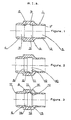
- Fig. 1 shows in section a ring 1 having externally a tube 2 with a mouth 2 ', in the center a reinforcement 3 and, at the other end, a tube 4 without internal mouth, but with an external slope (preferably a spherical sector) .
- the ring 1 comprises a duct 5, a groove 6 and a duct 7.
- the ducts 5 and 7 are of the same diameter and with a smooth wall.
- the groove 6 is of a substantially larger diameter with a smooth cylindrical wall.
- the groove 6 has shoulders 8 and 9 in opposite directions.
- Fig. 2 represents a ring identical to FIG. 1 but with a second groove 10, concentric with the first 6, and comprising a shoulder 11 (in the same direction as the shoulder 8) and a shoulder 12 replacing the shoulder 9 and more pronounced.
- Fig. 3 represents a ring identical to FIG. 1, but with a groove 13 concentric with the groove 6, at its center, so as to determine areas 14 and 15 as well as shoulders 11 and 16.
- this ring has the shoulders 8 and 11 in one direction, and 16 and 12 in the other direction.
- it is necessary to add the nose 17 of the ring which also plays the role of shoulder when the tube is flared.
- the crimping process is illustrated in Figs. 4 to 9.
- the ring 1 is threaded on the tube 18 so that it exceeds it.
- a sleeve 19 is applied to the tube to hold it in place, and possibly shells 30 can be provided to support the ring 1.
- the sleeves and shells prevent deformations of the tube in undesired places.
- the mandrel 20 is full and consists of three cylindrical parts of increasing diameters 21, 23, 25 determining between them shoulders 22 and 24. When the mandrel 20 is introduced inside the tube 18, the part 21 s' normally pushes down to the shoulder 22 slightly inclined so that the part 23 in turn penetrates inside the tube 18 flaring it at 26 until its periphery 27 abuts against the shoulder 24.
- the shoulder 24 exerts a very high pressure on the end section 27 of the tube 18, the wall of which is pushed back inside the ring 1.
- the tube 18 which is blocked in the sleeve 19 tends to deform only at the level of the ring 1 and enters its grooves 6 and 13.
- the wall 18 is supported on the various internal shoulders.
- the material, of which the tube is made up is packed and the wall tends to thicken instead of thinning as in the expansion, and also to harden, giving the end of the tube thus treated a higher robustness.
- the deformation 26 of the flared part of the tube 18 is applied to the nose 17 of the ring 1. After removal of the mandrel 20, the tube 18 remains crimped in the ring and has five anchoring points in relation to the shoulders 8 , 11, 16, 12 17. Finally the sleeve 19 is also removed.
- the tube 18 provided with its ring 1 is placed in the connector body 28 on which the nut 29 is screwed.
- the flared part of the tube 18 then protrudes from the ring 1 by a distance such that its end part comes into contact with the connection cone 28 so as to produce a direct mechanical connection between the tube 18 and the connection body 28, and possibly an additional seal.
- the present invention also applies to other tubes.
- the mandrels can be designed for tubes having any cross-section.
Abstract
Procédé de raccordement d'un tube que l'on déforme à l'intérieur d'une bague à gorge intérieure, caractérisé en ce que la déformation du tube (18) dans la bague (1) est obtenue par pression sur sa section terminale (27), un mandrin (20) étant placé provisoirement à l'intérieur du tube (18) et des manchons (19) à l'extérieur, la pression exercée sur la section terminale (27) du tube (18) engendrant la déformation de la paroi du dit tube (18) au niveau de la gorge (6) de la bague (1) de telle manière qu'elle en assure l'ancrage, après quoi le mandrin (20) et les manchons (19) sont retirés, et la bague (1) est enserrée dans le corps de raccord (28) et l'écrou (29) qui se visse sur lui. Application notamment pour les raccordements de tubes à faible diamètre et/ou à paroi mince.Method for connecting a tube which is deformed inside an inner grooved ring, characterized in that the deformation of the tube (18) in the ring (1) is obtained by pressing on its end section ( 27), a mandrel (20) being placed temporarily inside the tube (18) and sleeves (19) outside, the pressure exerted on the end section (27) of the tube (18) causing the deformation of the wall of said tube (18) at the level of the groove (6) of the ring (1) so that it anchors it, after which the mandrel (20) and the sleeves (19) are removed, and the ring (1) is enclosed in the connector body (28) and the nut (29) which screws onto it. Application in particular for the connection of tubes with small diameter and / or with thin wall.
Description
L'invention concerne les raccordements de tubes. Elle concerne notamment les raccordements de tubes de faible diamètre et/ou à paroi mince, tels ceux utilisés pour la distribution de carburant dans les moteurs d'avions ou d'automobiles.The invention relates to tube connections. It relates in particular to the connections of small diameter and / or thin-walled tubes, such as those used for the distribution of fuel in aircraft or automobile engines.
Généralement pour réaliser un tel raccordement, on munit d'abord l'extrémité externe du tube à raccorder d'une bague cylindrique ancrable sur la dite extrémité, puis on enserre la bague dans un corps de raccord avec un écrou se vissant sur lui. Il est impératif que l'ancrage de la bague sur le tube ne provoque pas de lignes ou de zônes d'affaiblissement, surtout en cas de faible épaisseur de la paroi du tube. Le procédé qui semble avoir le mieux satisfait à ces exigences techniques d' ancrage comporte la déformation par dudgeonnage de l'extrémité du tube à l'intérieur de la bague. Le procédé de dudgeonnage est très ancien, et consiste à introduire, dans le tube, un mandrin dont le diamètre est variable pour provoquer une pression radiale interne repoussant le tube contre la paroi interne de la bague prévue avec nervures et gorges. Selon ce procédé on introduit dans le tube un mandrin compressible axialement, puis à l'aide d'un système approprié on provoque l'extension de sa circonférence au niveau des gorges de la bague et l'on emboutit ainsi radialement la paroi du tube en direction du fond des dites gorges. Puis après avoir réalisé cette déformation du tube de l'intérieur, on supprime l'effort de compression et on retire le mandrin. Le tube reste ancré dans sa bague, et peut alors être raccordé de façon usuelle à l'aide d'un corps de raccord et un écrou se vissant sur lui.Generally to make such a connection, we first provide the outer end of the tube to be connected with a cylindrical ring anchored on said end, then we encircle the ring in a connector body with a nut screwing on it. It is imperative that the anchoring of the ring on the tube does not cause lines or zones of weakening, especially in the case of a thin wall of the tube. The method which seems to have best satisfied these technical anchoring requirements involves deformation by swaging the end of the tube inside the ring. The expansion method is very old, and consists in introducing, into the tube, a mandrel whose diameter is variable to cause an internal radial pressure pushing the tube against the internal wall of the ring provided with ribs and grooves. According to this process, an axially compressible mandrel is introduced into the tube, then using a suitable system, its circumference is extended at the level of the grooves of the ring, and the wall of the tube is thus radially stamped. direction of the bottom of the said gorges. Then after having carried out this deformation of the tube from the inside, the compression force is eliminated and the mandrel is removed. The tube remains anchored in its ring, and can then be connected in the usual way using a connector body and a nut screwing onto it.
Les bagues (ou manchons) les plus fréquemment utilisés sont relativement longues et, pour assurer un ancrage suffisant comportent deux gorges successives déterminant une nervure de séparation et une nervure d'extrémité. La déformation du tube étant limitée, la présence dans la bague de plusieurs nervures est nécessaire pour assurer un accrochage convenable.The most frequently used rings (or sleeves) are relatively long and, to ensure sufficient anchoring, comprise two successive grooves defining a separation rib and an end rib. The deformation of the tube being limited, the presence in the ring of several ribs is necessary to ensure proper attachment.
Bien qu'ayant donné dans l'ensemble satisfaction, ce procédé présente des difficultés et se révèle insuffisant pour satisfaire avec certitude aux exigences techniques de plus en plus sévères. D'abord le mandrin compressible est fragile et se rompt dans le cas de faible diamètre du tube, et le procédé est de plus en plus difficile à appliquer au fur et à mesure que l'épaisseur de la paroi du tube diminue. Au niveau des nervures et des gorges de la bague, par suite de l'expansion du diamètre, le tube se trouve étiré radialement et longitudinalement, et donc l'épaisseur de sa paroi légèrement diminuée, ce qui est sensible dans un tube à paroi très mince. La présence de nervures provoque des pliures du tube avec commencement de ligne d'affaiblissement, qui sont aggravées lors de l'enserrement de la bague dans le corps de raccord et de l'écrou de serrage. En outre, du fait de l'existence de deux gorges la surépaisseur extérieurer traditionnelle d'une bague correspond su,element à la gorge la plus centrale, et une zône mince correspond à la gorge d'extrémité, et cette zône est fragile.Although having given overall satisfaction, this process presents difficulties and proves to be insufficient to satisfy with certainty the increasingly severe technical requirements. First, the compressible mandrel is fragile and ruptures in the case of a small diameter of the tube, and the process becomes more and more difficult to apply as the thickness of the wall of the tube decreases. At the ribs and grooves of the ring, due to the expansion of the diameter, the tube is stretched radially and longitudinally, and therefore the thickness of its wall slightly reduced, which is noticeable in a tube with very wall slim. The presence of ribs causes bends in the tube with the beginning of the weakening line, which are aggravated when the ring is clamped in the fitting body and the tightening nut. In addition, due to the existence of two grooves, the traditional external thickness of a ring corresponds to, element with the most central groove, and a thin zone corresponds to the end groove, and this zone is fragile.
Pour remédier à ces inconvénients, l'inventeur a mis au point un procédé d'ancrage du type consistant à déformer un tube à l'intérieur d'une bague à gorge intérieure, caractérisé en ce que la déformation du tube est obtenue par pression sur la section terminale de sa paroi, un mandrin rigide plein à paroi lisse étant placé provisoirement à l'intérieur du tube (et empêchant toute déformation vers l'intérieur), la pression exercée longitudinalement à l'extrémité du dit tube engendrant la déformation par refoulement de la paroi de ce tube au niveau de la gorge de la bague de telle manière qu'elle assure une fixation indissociable entre la bague et le tube.To overcome these drawbacks, the inventor has developed an anchoring method of the type consisting in deforming a tube inside an inner grooved ring, characterized in that the deformation of the tube is obtained by pressing on the end section of its wall, a solid rigid mandrel with smooth wall being temporarily placed inside the tube (and preventing any deformation inwards), the pressure exerted longitudinally at the end of said tube causing the deformation by discharge of the wall of this tube at the level of the groove of the ring in such a way that it ensures an inseparable fixing between the ring and the tube.
Pour obtenir la déformation uniquement au niveau de la gorge (ou des gorges) de la bague, le tube (éventuellement avec sa bague) est maintenu extérieurement par un ou des manchons et/ou des coquilles, et intérieurement par le mandrin de diamètre approprié, de telle manière que la seule zône d'expansion soit déterminée par la gorge de la bague. Selon un mode d'exécution du procédé, l'introduction du mandrin dans le tube et la pression sur la section terminale de ce tube s'effectuent simultanément en fin de course du mandrin. A cet effet, le mandrin comporte un épaulement approprié pour buter, puis exercer une pression sur la section terminale du tube. Selon un autre mode d'exécution, le tube dépasse légèrement la bague et le mandrin comporte deux épaulements successifs, de telle manière que lors de son introduction dans le tube, le premier épaulement provoque un évasement du tube et le second exerce une pression sur la section terminale de ce même tube. Selon encore un autre mode de réalisation de l'invention, on utilise successivement deux mandrins. Le premier mandrin comporte un seul épaulement qui est appliqué sur la section terminale du tube et sert uniquement à exercer la pression nécessaire à la déformation au niveau de la ou des gorges de la bague. Pendant cette opération la partie du tube dépassant la bague est maintenue par un manchon approprié. Après retrait de ce premier mandrin, un second mandrin comportant un seul épaulement et une partie plus large est introduit dans le tube pour évaser la partie dépassant la bague et apliquer la déformation formée sur le nez de la dite bague.To obtain the deformation only at the level of the groove (or grooves) of the ring, the tube (possibly with its ring) is held externally by one or more sleeves and / or shells, and internally by the mandrel of appropriate diameter, so that the only area d expansion is determined by the groove of the ring. According to one embodiment of the method, the introduction of the mandrel into the tube and the pressure on the end section of this tube are carried out simultaneously at the end of the stroke of the mandrel. To this end, the mandrel has a suitable shoulder for abutting, then exerting pressure on the end section of the tube. According to another embodiment, the tube slightly protrudes from the ring and the mandrel has two successive shoulders, so that when it is introduced into the tube, the first shoulder causes the tube to flare and the second exerts pressure on the end section of this same tube. According to yet another embodiment of the invention, two mandrels are used successively. The first mandrel has a single shoulder which is applied to the end section of the tube and is used only to exert the pressure necessary for deformation at the level of the groove or grooves of the ring. During this operation, the part of the tube projecting beyond the ring is held in place by an appropriate sleeve. After removal of this first mandrel, a second mandrel comprising a single shoulder and a wider part is introduced into the tube to flare the part protruding from the ring and to apply the deformation formed on the nose of said ring.
L'invention porte non seulement sur le procédé, mais également sur le dispositif de raccordement. La bague utilisée comporte un conduit cylindrique sans nervure ni autre aspérité interne, mais avec une gorge large située au niveau d'une surépaisseur extérieure, prévue de préférence sensiblement en son milieu. Avantageusement, la bague comporte à l'intérieur de la première gorge, une deuxième gorge. Cette deuxième gorge a une largeur moindre, mais un diamètre supérieur à la première gorge. Cette deuxième gorge peut être prévue n'importe où dans le fond de la première gorge, par exemple, soit le long d'un bord de la première gorge, soit au centre de cette première gorge de telle manière qu'une plage circulaire de la dite première gorge subsiste de part et d'autre de la deuxième gorge, déterminant ainsi les épaulements d'ancrage et d'étanchéité nécessaires. Dans le cas de sertissage selon le procédé, dans une bague à une gorge, la paroi du tube présente deux zônes circulaires d'attachement correspondant aux deux épaulements déterminés par la gorge à l'intérieur de la bague. Dans le cas de sertissage dans une bauge à gorges concentriques, la paroi du tube présente trois ou quatre zônes circulaires d'attachement correspondant aux deux, ou trois épaulements déterminés par les deux gorges circulaires à l'intérieur de la bague (selon que la deuxième gorge est située à une extrémité ou non de la première gorge). Par ailleurs, la partie évasée du tube dépasse la bague et la zône de déformation (reliant la partie évasée à la partie non évasée) est alpliquée sur le nez de la dite bague, ce qui constitue un épaulement supplémentaire et donc une zône circulaire d'attachement supplémentaire.The invention relates not only to the method, but also to the connection device. The ring used has a cylindrical conduit without rib or other internal roughness, but with a wide groove located at an external allowance, preferably provided substantially in the middle. Advantageously, the ring has, inside the first groove, a second groove. This second groove has a smaller width, but a diameter greater than the first groove. This second groove can be provided anywhere in the bottom of the first groove, for example, either along an edge of the first groove, or in the center of this first groove in such a way that a circular area of the said first groove remains on either side of the second groove, thus determining the anchoring and sealing shoulders required. In the case of crimping according to the method, in a ring with a groove, the wall of the tube has two circular attachment zones corresponding to the two shoulders determined by the groove inside the ring. In the case of crimping in a concentric grooved gauge, the wall of the tube has three or four circular attachment zones corresponding to the two, or three shoulders determined by the two circular grooves inside the ring (depending on whether the second groove is located at one end or not of the first groove). Moreover, the flared part of the tube exceeds the ring and the deformation zone (connecting the flared portion to the non-flared portion) is in the pliquée on the nose of the said ring, which constitutes a further shoulder, and thus a circular area additional attachment.
Après l'obtention de la déformation de l'extrémité du tube, le mandrin et les manchons sont retirés et le tube serti dans sa bague peut alors être raccordé à l'aide d'un corps de raccord et de l'écrou se vissant sur lui.After obtaining the deformation of the end of the tube, the mandrel and the sleeves are removed and the tube crimped in its ring can then be connected using a connector body and the nut screwing on him.
Pour mieux faire comprendre l'invention il est donné ci-après des exemples de réalisation en référence aux dessins annexés dans lesquels :
- Fig. 1 à 3 sont des coupes de trois bagues selon l'invention,
- Fig. 4 à 9 montrent schématiqueqment les phases successives du procédé de sertissage du tube dans sa bague,
- Fig. 10 montre le raccordement final.
- Fig. 1 to 3 are sections of three rings according to the invention,
- Fig. 4 to 9 schematically show the successive phases of the process of crimping the tube in its ring,
- Fig. 10 shows the final connection.
La Fig. 1 représente en coupe une bague 1 présentant extérieurement une tubulure 2 avec une embouchure 2', au centre un renforcement 3 et, à l'autre extrémité, une tubulure 4 sans embouchure intérieure, mais avec une pente extérieure (de préférence un secteur sphérique). Intérieurement, et également de droite à gauche, la bague 1 comporte un conduit 5, une gorge 6 et un conduit 7. Les conduits 5 et 7 sont de même diamètre et à paroi lisse. La gorge 6 est d'un diamètre sensiblement plus grand avec une paroi lisse cylindrique. La gorge 6 présente des épaulements 8 et 9 en sens opposé.Fig. 1 shows in section a
La Fig. 2 représente une bague identique à la Fig. 1 mais avec une deuxième gorge 10, concentrique à la première 6, et comportant un épaulement 11 (du même sens que l'épaulement 8) et un épaulement 12 remplaçant l'épaulement 9 et plus prononcé.Fig. 2 represents a ring identical to FIG. 1 but with a
La Fig. 3 représente une bague identique à la Fig. 1, mais avec une gorge 13 concentrique à la gorge 6, en son centre, de manière à déterminer des plages 14 et 15 ainsi que des épaulements 11 et 16. Ainsi, cette bague présente les épaulements 8 et 11 dans un sens, et 16 et 12 dans l'autre sens. A ces quatre épaulements centraux, il faut ajouter le nez 17 de la bague, qui joue également le rôle d'épaulement lorsque le tube est évasé.Fig. 3 represents a ring identical to FIG. 1, but with a
Le procédé de sertissage est illustré par les Fig. 4 à 9. La bague 1 est enfilée sur le tube 18 de façon qu'il la dépasse. Un manchon 19 est appliqué sur le tube pour le maintenir en place, et éventuellement des coquilles 30 peuvent être prévues pour soutenir la bague 1. Les manchons et coquilles empêchent des déformations du tube à des endroits non désirés. Le mandrin 20 est plein et est constitué de trois parties cylindriques de diamètres croissants 21, 23, 25 déterminant entre elles des épaulements 22 et 24. Lorsque l'on introduit le mandrin 20 à l'intérieur du tube 18, la patie 21 s'enfonce normalement jusqu'à l'épaulement 22 légèrement incliné de telle manière que la partie 23 pénètre à son tour à l'intérieur du tube 18 l'évasant en 26 jusqu'à ce que son pourtour 27 vienne buter contre l'épaulement 24. En poursuivant sa pression, sous l'effet de moyens connus, l'épaulement 24 exerce une très forte pression sur la section terminale 27 du tube 18 dont la paroi se trouve repoussée à l'intérieur de la bague 1. Sous cette pression, le tube 18 qui est bloqué dans le manchon 19 tend à se déformer uniquement au niveau de la bague 1 et pénètre dans ses gorges 6 et 13. La pression continuant, la paroi 18 prend appui sur les différents é.paulements internes. Simultanément la matière, dont est constituée le tube, est tassée et la paroi à tendance à s'épaissir au lieu de s'amincir comme dans le dudgeonnage, et aussi à se durcir, conférant à l'extrémité du tube ainsi traité une robustesse supérieure. En outre la déformation 26 de la partie évasée du tube 18 est appliquée sur le nez 17 de la bague 1. Après retrait du mandrin 20, le tube 18 reste serti dans la bague et présente cinq points d'ancrage en relation avec les épaulements 8, 11, 16, 12 17. Finalement le manchon 19 est également retiré.The crimping process is illustrated in Figs. 4 to 9. The
Le tube 18 muni de sa bague 1 est placé dans le corps de raccord 28 sur lequel se visse l'écrou 29. La partie évasée du tube 18 dépasse alors de la bague 1 d'une distance telle que sa partie terminale vient en contact avec le cône de raccord 28 de façon à réaliser une liaison mécanique directe entre le tube 18 et le corps de raccord 28, et éventuellement une étanchéité supplémentaire.The
Bien que conçu plus particulièrement pour des petits tubes depetit diamètre et/ou à paroi mince pour lesquels le dudgeonnage est difficilement réalisable, la présente invention s'applique aussi aux autres tubes. De plus les mandrins peuvent être conçus pour des tubes ayant des sections quelconques.Although designed more particularly for small diameter and / or thin-walled tubes for which expansion is difficult to achieve, the present invention also applies to other tubes. In addition, the mandrels can be designed for tubes having any cross-section.
Claims (11)
Applications Claiming Priority (2)
| Application Number | Priority Date | Filing Date | Title |
|---|---|---|---|
| FR8305872A FR2543857B1 (en) | 1983-04-11 | 1983-04-11 | TUBE CONNECTION HAVING ANCHORAGE OF A RING ON ITS END |
| FR8305872 | 1983-04-11 |
Publications (2)
| Publication Number | Publication Date |
|---|---|
| EP0123600A1 true EP0123600A1 (en) | 1984-10-31 |
| EP0123600B1 EP0123600B1 (en) | 1988-06-22 |
Family
ID=9287708
Family Applications (1)
| Application Number | Title | Priority Date | Filing Date |
|---|---|---|---|
| EP84400702A Expired EP0123600B1 (en) | 1983-04-11 | 1984-04-10 | Connecting tube having a ring clamped at its end |
Country Status (13)
| Country | Link |
|---|---|
| US (2) | US4688318A (en) |
| EP (1) | EP0123600B1 (en) |
| JP (1) | JPS59205094A (en) |
| AU (2) | AU2663484A (en) |
| BR (1) | BR8401669A (en) |
| DE (1) | DE3472225D1 (en) |
| EG (1) | EG16430A (en) |
| ES (1) | ES531535A0 (en) |
| FR (1) | FR2543857B1 (en) |
| IL (1) | IL71489A0 (en) |
| IN (1) | IN160638B (en) |
| RO (1) | RO92497B (en) |
| YU (1) | YU65584A (en) |
Families Citing this family (19)
| Publication number | Priority date | Publication date | Assignee | Title |
|---|---|---|---|---|
| US4844517A (en) * | 1987-06-02 | 1989-07-04 | Sierracin Corporation | Tube coupling |
| US4835536A (en) * | 1987-12-21 | 1989-05-30 | Honeywell Inc. | Weather radar with turbulence detection |
| FR2642500B1 (en) * | 1989-01-30 | 1991-04-19 | Parker Hannifin Rak Sa | PROCESS FOR PRODUCING A SEALED CONNECTION FOR A RIGID TUBE AND CONNECTION THEREOF |
| US5058936A (en) * | 1989-02-23 | 1991-10-22 | Raychem Corporation | Method of forming a mechanical |
| DE4002494A1 (en) * | 1990-01-29 | 1991-08-08 | Airbus Gmbh | PIPE FITTING |
| US5445476A (en) * | 1993-09-30 | 1995-08-29 | Shell Oil Company | Reusable offshore platform jacket |
| US5447391A (en) * | 1993-09-30 | 1995-09-05 | Shell Oil Company | Offshore platform structure and system |
| US5741089A (en) * | 1994-12-23 | 1998-04-21 | Shell Offshore Inc. | Method for enhanced redeployability of hyjack platforms |
| US5551801A (en) * | 1994-12-23 | 1996-09-03 | Shell Offshore Inc. | Hyjack platform with compensated dynamic response |
| US5593250A (en) * | 1994-12-23 | 1997-01-14 | Shell Offshore Inc. | Hyjack platform with buoyant rig supplemental support |
| US5607194A (en) | 1995-04-20 | 1997-03-04 | Universal Enterprises, Inc. | Member and tube assembly |
| US6517126B1 (en) * | 2000-09-22 | 2003-02-11 | General Electric Company | Internal swage fitting |
| JP4992098B2 (en) * | 2007-06-05 | 2012-08-08 | 株式会社水研 | Non-bolt joint structure and method for forming non-bolt joint structure |
| GB2462814B (en) * | 2008-08-19 | 2010-10-06 | Rolls Royce Plc | Method of manufacturing thin wall isogrid casings |
| EP2184525B1 (en) * | 2008-11-06 | 2011-10-19 | Eifeler Maschinenbau GmbH | Pipe joint with a pipe and method for producing a joining section of a pipe joint |
| US9772056B2 (en) | 2009-03-05 | 2017-09-26 | Gates Corporation | Tube connector |
| US9091376B2 (en) * | 2010-12-30 | 2015-07-28 | Eaton Corporation | Method of forming an internal tube beadlock |
| US9982813B2 (en) * | 2015-03-27 | 2018-05-29 | Designed Metal Connections, Inc. | Swage fitting |
| CN112935817B (en) * | 2021-03-12 | 2022-11-15 | 四川明日宇航工业有限责任公司 | Machining method for aviation annular part |
Citations (10)
| Publication number | Priority date | Publication date | Assignee | Title |
|---|---|---|---|---|
| DE192072C (en) * | ||||
| FR1536521A (en) * | 1900-01-01 | Genevac Ltd | connecting element | |
| DE540825C (en) * | 1929-05-09 | 1932-01-07 | Ver Stahlwerke Akt Ges | Process for the formation of the socket end or the spigot end of pipes used for the production of safety welding socket connections |
| FR1064906A (en) * | 1952-10-22 | 1954-05-19 | British Oxygen Co Ltd | Joint of metal pipes in a metal part |
| US2857666A (en) * | 1950-12-11 | 1958-10-28 | Walter O Beyer | Making coupling assemblies |
| US3467414A (en) * | 1966-09-30 | 1969-09-16 | Ronald T Downing | Tube joint having buckled locking means |
| US3730567A (en) * | 1970-07-08 | 1973-05-01 | Axial Corp | Coupling sleeve |
| FR2171718A5 (en) * | 1972-02-02 | 1973-09-21 | Btr Industries Ltd | |
| US4130932A (en) * | 1975-11-11 | 1978-12-26 | Arkla Industries, Inc. | Method of joining a tube to a plate |
| GB2024973A (en) * | 1978-06-19 | 1980-01-16 | Ridenour Ralph | Tube Fitting Assembly With Deformable Seal |
Family Cites Families (17)
| Publication number | Priority date | Publication date | Assignee | Title |
|---|---|---|---|---|
| US2477676A (en) * | 1949-08-02 | Tubnable coupling member | ||
| US2685461A (en) * | 1949-09-22 | 1954-08-03 | Mueller Co | Pipe coupling |
| DE1022061B (en) * | 1955-03-19 | 1958-01-02 | Ver Kesselwerke Ag | Connection between an austenitic and a ferritic tube |
| US3188733A (en) * | 1961-07-28 | 1965-06-15 | Mcdowell Mfg Co | Torque joint |
| FR81781E (en) * | 1962-06-14 | 1963-11-08 | Commissariat Energie Atomique | Method and apparatus for sealing a tube on a sheath or the like |
| BE683803A (en) * | 1966-07-07 | 1966-12-16 | ||
| US3484123A (en) * | 1968-04-18 | 1969-12-16 | Boeing Co | Reuseable flareless tube coupling |
| US3711132A (en) * | 1970-06-17 | 1973-01-16 | Resistoflex Corp | Metal tube end fitting |
| US3778090A (en) * | 1972-05-18 | 1973-12-11 | Gen Motors Corp | Beaded tube with o-ring seal connection |
| SE7505866L (en) * | 1974-06-06 | 1975-12-08 | Boeing Co | COUPLING SLEEVE |
| GB1472458A (en) * | 1974-06-21 | 1977-05-04 | Shell Int Research | Apparatus and a method for treating a surface in particular for spraying an insulating foam on a wall |
| US3967840A (en) * | 1975-03-13 | 1976-07-06 | Caterpillar Tractor Co. | Joint and process for forming same |
| US4043160A (en) * | 1975-12-18 | 1977-08-23 | The Boeing Company | Internal tooling for swaging apparatus |
| FR2412778A1 (en) * | 1977-12-20 | 1979-07-20 | Eljika | Rubber hose ferrule attachment system - has outer part clamped against inner part in press for positive engagement |
| JPS5545979U (en) * | 1978-09-22 | 1980-03-26 | ||
| FR2437560A1 (en) * | 1978-09-26 | 1980-04-25 | Legris France Sa | Joint for high pressure hydraulic pipes - has sleeve of ductile material and nylon sealing ring |
| FR2488354A1 (en) * | 1980-08-06 | 1982-02-12 | Nadella | TRANSMISSION DEVICE COMPRISING A CARDAN JOINT OR OTHER COUPLING MEMBER |
-
1983
- 1983-04-11 FR FR8305872A patent/FR2543857B1/en not_active Expired
-
1984
- 1984-04-06 US US06/597,255 patent/US4688318A/en not_active Expired - Fee Related
- 1984-04-08 EG EG229/84A patent/EG16430A/en active
- 1984-04-09 AU AU26634/84A patent/AU2663484A/en not_active Abandoned
- 1984-04-09 RO RO114210A patent/RO92497B/en unknown
- 1984-04-10 YU YU00655/84A patent/YU65584A/en unknown
- 1984-04-10 IL IL71489A patent/IL71489A0/en unknown
- 1984-04-10 BR BR8401669A patent/BR8401669A/en unknown
- 1984-04-10 EP EP84400702A patent/EP0123600B1/en not_active Expired
- 1984-04-10 DE DE8484400702T patent/DE3472225D1/en not_active Expired
- 1984-04-11 JP JP59072589A patent/JPS59205094A/en active Pending
- 1984-04-11 ES ES531535A patent/ES531535A0/en active Granted
- 1984-04-17 IN IN269/MAS/84A patent/IN160638B/en unknown
-
1987
- 1987-01-15 US US07/006,306 patent/US4805945A/en not_active Expired - Fee Related
-
1988
- 1988-01-06 AU AU10098/88A patent/AU1009888A/en not_active Abandoned
Patent Citations (10)
| Publication number | Priority date | Publication date | Assignee | Title |
|---|---|---|---|---|
| DE192072C (en) * | ||||
| FR1536521A (en) * | 1900-01-01 | Genevac Ltd | connecting element | |
| DE540825C (en) * | 1929-05-09 | 1932-01-07 | Ver Stahlwerke Akt Ges | Process for the formation of the socket end or the spigot end of pipes used for the production of safety welding socket connections |
| US2857666A (en) * | 1950-12-11 | 1958-10-28 | Walter O Beyer | Making coupling assemblies |
| FR1064906A (en) * | 1952-10-22 | 1954-05-19 | British Oxygen Co Ltd | Joint of metal pipes in a metal part |
| US3467414A (en) * | 1966-09-30 | 1969-09-16 | Ronald T Downing | Tube joint having buckled locking means |
| US3730567A (en) * | 1970-07-08 | 1973-05-01 | Axial Corp | Coupling sleeve |
| FR2171718A5 (en) * | 1972-02-02 | 1973-09-21 | Btr Industries Ltd | |
| US4130932A (en) * | 1975-11-11 | 1978-12-26 | Arkla Industries, Inc. | Method of joining a tube to a plate |
| GB2024973A (en) * | 1978-06-19 | 1980-01-16 | Ridenour Ralph | Tube Fitting Assembly With Deformable Seal |
Also Published As
| Publication number | Publication date |
|---|---|
| DE3472225D1 (en) | 1988-07-28 |
| US4805945A (en) | 1989-02-21 |
| RO92497B (en) | 1988-07-01 |
| IN160638B (en) | 1987-07-25 |
| EP0123600B1 (en) | 1988-06-22 |
| IL71489A0 (en) | 1984-07-31 |
| RO92497A (en) | 1988-06-30 |
| BR8401669A (en) | 1984-11-20 |
| FR2543857A1 (en) | 1984-10-12 |
| AU1009888A (en) | 1988-04-21 |
| US4688318A (en) | 1987-08-25 |
| ES8505561A1 (en) | 1985-06-01 |
| FR2543857B1 (en) | 1986-05-09 |
| EG16430A (en) | 1987-04-30 |
| AU2663484A (en) | 1984-10-18 |
| JPS59205094A (en) | 1984-11-20 |
| YU65584A (en) | 1989-02-28 |
| ES531535A0 (en) | 1985-06-01 |
Similar Documents
| Publication | Publication Date | Title |
|---|---|---|
| EP0123600A1 (en) | Connecting tube having a ring clamped at its end | |
| EP1144900B1 (en) | Device for quick connection of a tube to a rigid element | |
| FR2705432A1 (en) | Connection system by sliding sleeves, for cylindrical plastic tubes. | |
| EP1807648B1 (en) | Segmented locking ring, and corresponding assembly and mounting method | |
| EP0151889A1 (en) | Pipe joint and method of assembling it | |
| FR2847646A1 (en) | Tube joint for connecting a tube to fluid operated apparatus has annular projection provided at the end surface of the nut and which is screwed to the joint body to regulate the screwing amount of the nut on the joint body | |
| EP1319147B1 (en) | Coupling for connecting a tubular fitting to a pipe | |
| FR2583928A1 (en) | DEVICE FOR CONNECTION HOLDING THE PRESSURE OF THE OUTSIDE CONDUCTOR OF A COAXIAL CABLE | |
| FR2818338A1 (en) | SEALING BELLOWS, TRANSMISSION JOINT OF SUCH A BELLOWS AND METHOD OF FIXING SUCH A BELLOWS | |
| FR2740531A1 (en) | IMPROVEMENT TO A DEVICE FOR CONNECTING A TUBE TO A TIP | |
| FR2862740A1 (en) | Joint device for connecting refrigerant pipes in automotive air-conditioning system, has retaining portions which return to their initial shapes after first pipe section has been completely inserted into second pipe section | |
| EP0737114B1 (en) | Shrinking method | |
| EP3164634A1 (en) | Fluid connector with pre-positioned crimping collar | |
| EP1958715B1 (en) | Method for assembling at least two elements by means of a blind rivet | |
| CA2048207C (en) | Inserted collar for joining tubes; tube assembly using said collar | |
| FR2694348A1 (en) | Radial clamping device for a pipe and connection piece comprising this device. | |
| FR2594205A1 (en) | End connector for a flexible pipe | |
| FR2642802A1 (en) | BLIND MOUNTING NUT AND CRIMPING ON ANY WALL | |
| FR2767181A1 (en) | DEVICE FOR QUICK CONNECTION OF A TUBE TO A RIGID ELEMENT | |
| EP0864798B2 (en) | Method for connecting a hose to a rigid pipe; coupling and retaining ring for carrying out the method | |
| FR2652773A1 (en) | Method of obtaining a flanged bush, especially intended for the connection of a pipe to a coupling, and device for its implementation | |
| EP1108939B1 (en) | Process for connecting fluid circuits and and connector for carrying out the process | |
| FR2844026A1 (en) | Detachable sealed connector for supple pipe, e.g. for gas, incorporates ring with axial bore and front and rear end clamping edges | |
| FR2873184A1 (en) | Compression fitting for aeronautic field, has titanium ring with ellipsoidal shape front part defining fastening point, median part defining shoulder and conical groove, and rear part defining another point and outer conical section | |
| FR2574136A1 (en) | Three section blind anchor nut |
Legal Events
| Date | Code | Title | Description |
|---|---|---|---|
| PUAI | Public reference made under article 153(3) epc to a published international application that has entered the european phase |
Free format text: ORIGINAL CODE: 0009012 |
|
| AK | Designated contracting states |
Designated state(s): AT BE CH DE FR GB IT LI LU NL SE |
|
| RBV | Designated contracting states (corrected) |
Designated state(s): BE DE GB IT LU NL SE |
|
| 17P | Request for examination filed |
Effective date: 19850620 |
|
| 17Q | First examination report despatched |
Effective date: 19860604 |
|
| GRAA | (expected) grant |
Free format text: ORIGINAL CODE: 0009210 |
|
| AK | Designated contracting states |
Kind code of ref document: B1 Designated state(s): BE DE GB IT LU NL SE |
|
| REF | Corresponds to: |
Ref document number: 3472225 Country of ref document: DE Date of ref document: 19880728 |
|
| ITF | It: translation for a ep patent filed |
Owner name: MODIANO & ASSOCIATI S.R.L. |
|
| GBT | Gb: translation of ep patent filed (gb section 77(6)(a)/1977) | ||
| BECA | Be: change of holder's address |
Free format text: 880622 *ERMETO-HYDEXCO:22 BOULEVARD DE L'INDUSTRIE, F-41000 BLOIS |
|
| BECH | Be: change of holder |
Free format text: 880622 *ERMETO-HYDEXCO:22 BOULEVARD DE L'INDUSTRIE, F-41000 BLOIS |
|
| REG | Reference to a national code |
Ref country code: GB Ref legal event code: 732 |
|
| PG25 | Lapsed in a contracting state [announced via postgrant information from national office to epo] |
Ref country code: GB Effective date: 19890410 |
|
| PG25 | Lapsed in a contracting state [announced via postgrant information from national office to epo] |
Ref country code: SE Effective date: 19890411 |
|
| PLBE | No opposition filed within time limit |
Free format text: ORIGINAL CODE: 0009261 |
|
| STAA | Information on the status of an ep patent application or granted ep patent |
Free format text: STATUS: NO OPPOSITION FILED WITHIN TIME LIMIT |
|
| PG25 | Lapsed in a contracting state [announced via postgrant information from national office to epo] |
Ref country code: LU Free format text: LAPSE BECAUSE OF NON-PAYMENT OF DUE FEES Effective date: 19890430 Ref country code: BE Effective date: 19890430 |
|
| 26N | No opposition filed | ||
| PGFP | Annual fee paid to national office [announced via postgrant information from national office to epo] |
Ref country code: DE Payment date: 19890609 Year of fee payment: 6 |
|
| NLS | Nl: assignments of ep-patents |
Owner name: FIRMA ERMETO TE BLOIS, FRANKRIJK. |
|
| NLT1 | Nl: modifications of names registered in virtue of documents presented to the patent office pursuant to art. 16 a, paragraph 1 |
Owner name: ERMETO-HYDEXCO TE BLOIS, FRANKRIJK. |
|
| BERE | Be: lapsed |
Owner name: ERMETO-HYDEXCO Effective date: 19890430 |
|
| PG25 | Lapsed in a contracting state [announced via postgrant information from national office to epo] |
Ref country code: NL Effective date: 19891101 |
|
| GBPC | Gb: european patent ceased through non-payment of renewal fee | ||
| NLV4 | Nl: lapsed or anulled due to non-payment of the annual fee | ||
| PG25 | Lapsed in a contracting state [announced via postgrant information from national office to epo] |
Ref country code: DE Effective date: 19910101 |
|
| EUG | Se: european patent has lapsed |
Ref document number: 84400702.1 Effective date: 19900412 |