EP0122596A1 - Wälzringspindeltrieb - Google Patents
Wälzringspindeltrieb Download PDFInfo
- Publication number
- EP0122596A1 EP0122596A1 EP84104061A EP84104061A EP0122596A1 EP 0122596 A1 EP0122596 A1 EP 0122596A1 EP 84104061 A EP84104061 A EP 84104061A EP 84104061 A EP84104061 A EP 84104061A EP 0122596 A1 EP0122596 A1 EP 0122596A1
- Authority
- EP
- European Patent Office
- Prior art keywords
- spindle
- drive
- roller bearing
- drive spindle
- rolling
- Prior art date
- Legal status (The legal status is an assumption and is not a legal conclusion. Google has not performed a legal analysis and makes no representation as to the accuracy of the status listed.)
- Granted
Links
Images


Classifications
-
- F—MECHANICAL ENGINEERING; LIGHTING; HEATING; WEAPONS; BLASTING
- F16—ENGINEERING ELEMENTS AND UNITS; GENERAL MEASURES FOR PRODUCING AND MAINTAINING EFFECTIVE FUNCTIONING OF MACHINES OR INSTALLATIONS; THERMAL INSULATION IN GENERAL
- F16H—GEARING
- F16H25/00—Gearings comprising primarily only cams, cam-followers and screw-and-nut mechanisms
- F16H25/18—Gearings comprising primarily only cams, cam-followers and screw-and-nut mechanisms for conveying or interconverting oscillating or reciprocating motions
- F16H25/20—Screw mechanisms
- F16H25/22—Screw mechanisms with balls, rollers, or similar members between the co-operating parts; Elements essential to the use of such members
- F16H25/2285—Screw mechanisms with balls, rollers, or similar members between the co-operating parts; Elements essential to the use of such members with rings engaging the screw shaft with the inner perimeter, e.g. using inner rings of a ball bearing
- F16H25/2295—Rings which are inclined or can pivot around an axis perpendicular to the screw shaft axis
Definitions
- the invention relates to a roller ring spindle drive with a drive spindle, at least one roller bearing and an output housing or the like, the roller bearing acting as a transmission element between the drive spindle and the output housing, preferably having at least one roller ring engaging in the threaded groove of the drive spindle, the roller bearing being arranged eccentrically is, the central axis of the roller bearing is inclined with respect to the longitudinal axis of the drive spindle and the output housing has at least one roller bearing receptacle.
- roller ring spindle drives In the case of roller ring spindle drives, the rotational movement of the drive spindle is converted into a translational movement of the drive housing by the roller bearing - as a transmission element between the drive spindle and the output housing.
- the roller bearing preferably with a roller ring, engages in the threaded groove of the drive spindle;
- the rolling ring can be connected to the inner ring of the rolling bearing, but it can also be formed as part of the inner ring of the rolling bearing on the inside of the inner ring of the rolling bearing.
- the desired kinematics between the drive spindle and the roller bearing makes it necessary that the roller bearing is arranged eccentrically on the one hand, and that on the other hand the central axis of the roller bearing relative to the longitudinal axis of the An drive spindle is inclined. Since the central axis of the roller bearing is now inclined with respect to the longitudinal axis of the drive spindle, the statement that the roller bearing is arranged eccentrically is somewhat crooked, but is still common.
- the rolling bearing running plane is defined as the plane that passes through the center of the rolling bearing and on which the central axis is perpendicular, then the eccentric arrangement of the rolling bearing means that the longitudinal axis of the Drive spindle is not in the center of the rolling bearing through the rolling bearing running level.
- the rolling bearing receptacle is rotationally symmetrical. Since the central axis of the roller bearing must now be inclined with respect to the longitudinal axis of the drive spindle, a roller bearing receiving body, which is used to realize the roller bearing holder, is provided and is divided in the axial direction; d. H. two complementary halves of the rolling bearing receiving body are each provided with part of the rolling bearing receptacle. Consequently, the rolling bearing can be inserted axially, that is in the direction of its central axis, in the first part of the rolling bearing receptacle and the rolling bearing receptacle can then be completed by its second part.
- the invention is therefore based on the object of specifying a rolling ring spindle drive which is improved with respect to the friction losses and thus the efficiency.
- the rolling ring spindle drive according to the invention in which the previously derived and described object is achieved, is now and essentially characterized in that the rolling bearing receptacle goes over a maximum of 180 °, so that the rolling bearing is perpendicular to its central axis, i.e. in the rolling bearing running plane, in the Rolling bearing holder can be inserted.
- a rotationally symmetrical rolling bearing receptacle which completely accommodates the outer ring of the rolling bearing is not necessary, that it is sufficient to absorb the forces coming from the drive spindle and to be transmitted to the driven housing via the rolling bearing if the rolling bearing receptacle only supports the outer ring of the rolling bearing partially records.
- the circumferential angle at which the roller bearing is supported depends on the individual case, in particular on the forces to be transmitted.
- the upper limit is 180 0 , however, so that the rolling bearing can be inserted into the rolling bearing receptacle perpendicular to its central axis, that is to say in the rolling bearing running plane.
- a rolling bearing receiving body is provided within the output housing and the rolling bearing receiving body has the rolling bearing receptacle.
- the rolling ring spindle drive according to the invention can also be designed in this way.
- an embodiment is particularly advantageous, which is characterized in that the output housing itself is provided with the roller bearing receptacle, that is to say that a special rolling bearing receptacle body is not provided.
- the eccentricity of the rolling bearing is sufficiently large, it is conceivable to design the rolling bearing receiving body or the output housing in one piece - at least in the area of the rolling bearing receptacle - and still have the possibility of inserting the rolling bearing into the rolling bearing receptacle.
- an embodiment of the rolling ring spindle drive according to the invention which is characterized in that the rolling bearing receiving body or the driven housing is divided in the radial direction, is advantageous, in particular in terms of production engineering, in which case only a part of the rolling bearing receiving body divided in the radial direction or that in the radial direction Direction of the divided output housing is provided with the rolling bearing mount.
- the drive spindle is adjustable in the radial direction relative to the rolling bearing.
- an embodiment is easier to implement, which is characterized in that the rolling bearing receiving body is adjustable in the radial direction relative to the drive spindle.
- the output housing has radially extending threaded bores and the rolling bearing receiving body can be adjusted radially with the aid of set screws guided in the threaded bores.
- Rolling ring spindle drives of the type in question are often designed with two (or more) rolling bearings and then with two (or more) rolling bearing mounts.
- a further teaching of the invention which is also of particular importance when detached from the teaching of the invention explained above, is that at least one roller bearing receptacle can be adjusted in the axial direction relative to the drive spindle.
- a first embodiment can then be characterized in that both roller bearing receptacles can be adjusted in the axial direction relative to the drive spindle.
- Embodiment is characterized in that the first roller bearing holder is adjustable in the axial direction relative to the drive spindle and the drive spindle - by means of the first roller bearing holder or by means of the first roller bearing - is adjustable in the axial direction relative to the second roller bearing holder.
- a rolling ring spindle drive according to the invention is characterized in that the inclination between the central axis of the rolling bearing and the longitudinal axis of the drive spindle corresponds to the pitch of the drive spindle in the force application circuit.
- the force should be transmitted from the drive spindle to the rolling bearing at a point of application of force, generally to the rolling ring that engages in the threaded groove of the drive spindle.
- a force application point cannot be realized, rather a crescent-shaped force application surface results.
- force application circle means the circle on which the - theoretical - force application points lie.
- the force from the drive spindle at a force application point should theoretically be transferred to the rolling bearing, usually on the rolling ring that engages in the threaded groove of the drive spindle, it is to be ensured constructively that the actually effective - crescent-shaped - Force application area approaches as far as possible the theoretically intended, a force application point.
- a further teaching of the invention which is also of particular importance, separate from the other teaching of the invention, is that the radius of curvature of the rolling ring engaging in the thread groove of the drive spindle is approximately 0.7 to 0.9 times as large as the radius of curvature of the thread groove to make the drive spindle.
- the determination of where and at what angle the rolling ring comes into engagement with the threaded groove of the drive spindle is determined by considerations which lead to different results. Since the rotational movement of the drive spindle is to be converted into a translational movement of the output housing, it is actually desirable that the rolling ring comes into engagement with the threaded groove of the drive spindle as far out as possible and at an angle of almost 90 °. From the point of view of the utilization of the cross section of the thread web of the drive spindle, however, it is desirable that the rolling ring is as far inside as possible with the Drive spindle comes into engagement. The previously given teaching to choose the relevant radii of curvature so that the tangent to the rolling ring in the force application circle runs at approximately 45 ° to the longitudinal axis of the drive spindle is an optimal compromise.
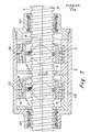
- the figures show a rolling ring spindle drive, which initially and essentially includes a drive spindle 1, two rolling bearings 2 and an output housing 3.
- the roller bearings 2 act as a transmission element between the drive spindle 1 and the output housing 3, namely the roller bearings 2 each have a roller ring 5 which engages in the threaded groove 4 of the drive spindle 1, the roller bearings 2 are arranged eccentrically, the central axes 6 of the roller bearings 2 inclined with respect to the longitudinal axis 7 of the drive spindle 1 and the output housing 3 has two roller bearing receptacles 8.
- the rolling ring 5 is formed as part of the inner ring 9 of the rolling bearing 2 on the inside of the inner ring 9 of the rolling bearing 2.
- the rolling ring 5 is a separate component connected to the inner ring 9 of the rolling bearing 2.
- the rolling bearings 2 belonging to the rolling ring spindle drive according to the invention consist, as usual, of the inner ring 9, of an outer ring 10 and of rolling elements 11, balls in the exemplary embodiments shown.
- the axis is defined by the center of the roller bearing 2.
- the plane that passes through the center of the rolling bearing 2 and on which the central axis 6 is perpendicular is defined as the rolling bearing running plane 12.
- each rolling bearing receptacle 8 goes over a maximum of 180 °, in the exemplary embodiments goes exactly over 180 °.
- each roller bearing 2 can be inserted into the associated roller bearing receptacle 8 perpendicular to its central axis 6, that is to say in the roller bearing running plane 12.
- a rotationally symmetrical outer ring 10 of the roller bearing 2 completely receiving roller bearing receptacle 8 is not necessary that it is sufficient to accommodate the forces coming from the drive spindle 1 and transmitted via the roller bearing 2 to the output housing 3 if each roller bearing receptacle 8 only partially receives the outer ring 10 of the associated roller bearing 2 .
- FIGS. 1 to 4 In the exemplary embodiments of a rolling ring spindle drive according to the invention, which are shown in FIGS. 1 to 4, two rolling bearing receiving bodies 13 are provided within the output housing 3, each of which has a rolling bearing receptacle 8.
- FIGS. 5 and 6 indicate an exemplary embodiment of a rolling ring spindle drive according to the invention, in which the output housing 3 itself is provided with the rolling bearing receptacles 8.
- the roller bearing receiving bodies 13, in the exemplary embodiment according to FIGS. 5 and 6, the output housing 3 is divided in the radial direction. This is more advantageous, particularly in terms of production technology, than an also conceivable one-piece design of the rolling bearing receiving body or the output housing.
- only a part of the roller bearing receptacle bodies 13 which are divided in the radial direction is provided with the roller bearing receptacle 8.
- each part of the driven housing 3 divided in the radial direction has a roller bearing receptacle 8 for a roller bearing 2.
- the figures show a preferred embodiment of the roller ring spindle drive according to the invention, as the degree of eccentricity 14 of the roller bearings 2 is adjustable, so that an employment between roller bearing 2 and drive spindle 1 is possible.
- the roller bearing receiving body 13 can be adjusted in the radial direction relative to the drive spindle 1.
- the output housing 3 radially extending threaded bores 15 and the rolling bearing receiving body 13 can be adjusted radially with the aid of set screws 16 guided in the threaded bores 15.
- the dimension of the eccentricity 14 of the rolling bearing 2 is adjustable, that is, a possibility of employment between the rolling bearing 2 and the drive spindle 1 is realized.
- the roller bearing receptacles 8 can also be adjusted in the axial direction relative to the drive spindle 1, or, as far as the functions are concerned, the drive spindle 1 can be adjusted in the axial direction relative to the roller bearing receptacles 8. As a result, axial adjustment between the roller bearing receptacles 8 and the drive spindle 1 is also possible.
- roller ring spindle drives according to the invention are shown, which have two roller bearings 2 and two roller bearing receptacles 8.
- the previously explained possibility of axial adjustment between the roller bearing receptacles 8 and the drive spindle 1 is realized in that the first roller bearing receptacle 8 is adjustable in the axial direction relative to the drive spindle 1 and the drive spindle 1 - by means of the first roller bearing receptacle 8 or by means of the first roller bearing 2 - is adjustable in the axial direction relative to the second roller bearing receptacle 8.
- a rolling ring spindle drive with a particularly small play between the drive spindle 1 and the output housing 3 is realized.
- roller ring spindle drives which are shown in the figures, are those in which the inclination between the central axes 6 of the roller bearings 2 and the longitudinal axis 7 of the drive spindle 1 corresponds to the slope of the drive spindle 1 in the force application circuit 17.
- Force application circle 17 means the circle on which the - theoretical - force application points lie between the drive spindle 1 and the rolling rings 5. Theoretically desired - transmission of the force from the drive spindle 1 to the rolling rings 5 at a point of application of force - cannot be realized because of the elasticity of the materials which come into engagement with one another, but rather always results in a crescent-shaped area of application of force.
- the radius of curvature 18 of the roller rings 5 engaging in the thread groove 4 of the drive spindle 1 is selected as a function of the radius of curvature 19 of the thread groove 4 so that in the force application circle 10 the tangent 20 to the roller ring 5 is at approximately 45 ° Longitudinal axis 7 of the drive spindle 1 runs.
- the drive spindle 1 is mounted in the output housing 3 via radial bearings 21.
Landscapes
- Engineering & Computer Science (AREA)
- General Engineering & Computer Science (AREA)
- Mechanical Engineering (AREA)
- Rolling Contact Bearings (AREA)
- Transmission Devices (AREA)
- Reduction Rolling/Reduction Stand/Operation Of Reduction Machine (AREA)
- Spinning Or Twisting Of Yarns (AREA)
Abstract
Description
- Die Erfindung betrifft einen Wälzringspindeltrieb mit einer Antriebsspindel, mindestens einem Wälzlager und einem Abtriebsgehäuse od. dgl., wobei das Wälzlager als Übertragungselement zwischen der Antriebsspindel und dem Abtriebsgehäuse wirksam ist, vorzugsweise mindestens einen in die Gewindenut der Antriebsspindel eingreifenden Wälzring aufweist, das Wälzlager exzentrisch angeordnet ist, die Mittelachse des Wälzlagers gegenüber der Längsachse der Antriebsspindel geneigt ist und das Abtriebsgehäuse mindestens eine Wälzlageraufnahme aufweist.
- Wälzringspindeltriebe der zuvor in ihrem grundsätzlichen Aufbau beschriebenen Art sind vielfach bekannt (vgl. das DE-GM 19 92 325, die DE-OS 19 49 049, die DE-AS 22 62 062, die DL-PS 51 174, die FR-PS 14 87 424, die GB-PS 6 29 993 sowie die US-PSen 24 77 701, 24 82 082, 24 88 256, 25 25 326, 25 56 572, 26 11 280, 26 16 302, 27 78 239 und 29 61 887). Gleichwohl-darf zunächst noch erläuternd folgendes ausgeführt werden:
- Wälzringspindeltriebe dienen dazu, eine Rotationsbewegung - der Antriebsspindel - in eine Translationsbewegung - des Antriebsgehäuses - umzusetzen. Daraus folgt schon, daß es sich bei dem Abtriebsgehäuse nicht um ein übliches - geschlossenes - Gehäuse handeln muß. Vielmehr kann auch ein Abtriebsrahmen od. dgl. vorgesehen sein.
- Bei Wälzringspindeltrieben wird die Rotationsbewegung der Antriebsspindel durch das Wälzlager - als Übertragungsglied zwischen der Antriebsspindel und dem Abtriebsgehäuse - in eine Translationsbewegung des Abtriebsgehäuses umgesetzt. Dazu greift das Wälzlager, vorzugsweise mit einem Wälzring, in die Gewindenut der Antriebsspindel ein; der Wälzring kann mit dem Innenring des Wälzlagers verbunden sein, er kann aber auch als Teil des Innenringes des Wälzlagers an der Innenseite des Innenringes des Wälzlagers ausgebildet sein.
- Die gewünschte Kinematik zwischen der Antriebsspindel und dem Wälzlager macht es erforderlich, daß einerseits das Wälzlager exzentrisch angeordnet ist, daß andererseits die Mittelachse des Wälzlagers gegenüber der Längsachse der Antriebsspindel geneigt ist. Da nun die Mittelachse des Wälzlagers gegenüber der Längsachse der Antriebsspindel geneigt ist, ist die Aussage, wonach das Wälzlager exzentrisch angeordnet ist, etwas schief, gleichwohl üblich. Definiert man bei einem Wälzlager neben der Mittelachse als der Achse durch den Mittelpunkt des Wälzlagers noch die Wälzlagerlaufebene als die Ebene, die durch den Mittelpunkt des Wälzlagers geht und auf der die Mittelachse senkrecht steht, so bedeutet die exzentrische Anordnung des Wälzlagers, daß die Längsachse der Antriebsspindel nicht im Mittelpunkt des Wälzlagers durch die Wälzlagerlaufebene geht.
- Im Stand der Technik, von dem die Erfindung ausgeht, ist die Wälzlageraufnahme rotationssymmetrisch. Da nun die Mittelachse des Wälzlagers gegenüber der Längsachse der Antriebsspindel geneigt sein muß, ist ein - der Realisierung der Wälzlageraufnahme dienender - Wälzlageraufnahmekörper vorgesehen, der in axialer Richtung geteilt ist; d. h. zwei sich ergänzende Hälften des Wälzlageraufnahmekörpers sind jeweils mit einem Teil der Wälzlageraufnahme versehen. Folglich kann das Wälzlager axial, also in Richtung seiner Mittelachse, in den ersten Teil der Wälzlageraufnahme eingesetzt werden und die Wälzlageraufnahme danach durch ihren zweiten Teil komplettiert werden.
- Die Tatsache, daß bei den bekannten Wälzringspindeltrieben der Wälzlageraufnahmekörper in axialer Richtung geteilt ist und jeder der beiden sich ergänzenden Hälften mit einem Teil der Wälzlageraufnahme versehen ist, ist nachteilig, weil schon die geringste, wegen nicht vermeidbarer Toleranzen auch nicht vermeidbare fehlerhafte'Zuordnung der beiden Hälften des Wälzlageraufnahmekörpers dazu führt, daß die Wälzlageraufnahme nicht die vorgegebene Konfiguration und nicht die vorgegebene Zuordnung zur Antriebsspindel hat und folglich ihrer Funktion nicht optimal genügen kann. Im Ergebnis treten Reibungsverluste auf, so daß bei allen bekannten Wälzringspindeltrieben der mechanische Wirkungsgrad bei der Umsetzung der Rotationsbewegung der Antriebsspindel in eine Translationsbewegung des Abtriebsgehäuses zu wünschen übrig läßt.
- Der Erfindung liegt also die Aufgabe zugrunde, einen bezüglich der Reibungsverluste und damit des Wirkungsgrades verbesserten Wälzringspindeltrieb anzugeben.
- Der erfindungsgemäße Wälzringspindeltrieb, bei dem die zuvor hergeleitete und dargelegte Aufgabe gelöst ist, ist nun zunächst und im wesentlichen dadurch gekennzeichnet, daß die Wälzlageraufnahme über maximal 180° geht, - so daß das Wälzlager senkrecht zu seiner Mittelachse, also in der Wälzlagerlaufebene, in die Wälzlageraufnahme eingeschoben werden kann.
- Erfindungsgemäß ist erkannt worden, daß eine rotationssymmetrische, den Außenring des Wälzlagers komplett aufnehmende Wälzlageraufnahme nicht erforderlich ist, daß es zur Aufnahme der von der Antriebsspindel kommenden und über das Wälzlager auf das Abtriebsgehäuse zu übertragenden Kräfte vielmehr ausreicht, wenn die Wälzlageraufnahme den Außenring des Wälzlagers nur teilweise aufnimmt. Über welchen Umfangswinkel die Wälzlageraufnahme geht, hängt vom Einzelfall ab, insbesondere von den zu übertragenden Kräften. Die obere Grenze liegt jedoch bei 1800, so daß das Wälzlager senkrecht zu seiner Mittelachse, also in der Wälzlagerlaufebene, in die Wälzlageraufnahme eingeschoben werden kann.
- Bei dem erfindungsgemäßen Wälzringspindeltrieb ist also eine Teilung des Wälzlageraufnahmekörpers in axialer Richtung nicht erforderlich. Daraus resultiert dann, daß eine einteilige Wälzlageraufnahme verwirklicht werden kann, so daß das im Stand der Technik vorhandene, weiter oben erläuterte Problem, daß die Wälzlageraufnahme nicht die vorgegebene Konfiguration und nicht die vorgegebere Zuordnung zur Antriebsspindel hat, nicht auftritt.
- Im einzelnen gibt es verschiedene Möglichkeiten, den erfindungsgemäßen Wälzringspindeltrieb auszugestalten und weiterzubilden, was im folgenden nur beispielhaft erläutert werden soll.
- Weiter oben ist bereits ausgeführt, daß bei den im Stand der Technik bekannten Wälzringspindeltrieben innerhalb des Abtriebsgehäuses ein Wälzlageraufnahmekörper vorgesehen ist und der Wälzlageraufnahmekörper die Wälzlageraufnahme aufweist. So kann auch der erfindungsgemäße Wälzringspindeltrieb ausgeführt sein. Besonders vorteilhaft ist jedoch eine Ausführungsform, die dadurch gekennzeichnet ist, daß das Abtriebsgehäuse selbst mit der Wälzlageraufnahme versehen ist, ein besonderer Wälzlageraufnahmekörper also nicht vorgesehen ist.
- Wenn bei dem erfindungsgemäßen Wälzringspindeltrieb die Exzentrizität des Wälzlagers hinreichend groß ist, so ist es denkbar, den Wälzlageraufnahmekörper bzw. das Abtriebsgehäuse - jedenfalls im Bereich der Wälzlageraufnahme - einteilig auszuführen und trotzdem die Möglichkeit zu haben, das Wälzlager in die Wälzlageraufnahme einzuschieben. Vorteilhafter, insbesondere in fertigungstechnischer Hinsicht, ist jedoch eine Ausführungsform des erfindungsgemäßen Wälzringspindeltriebes, die dadurch gekennzeichnet ist, daß der Wälzlageraufnahmekörper bzw. das Abtriebsgehäuse in radialer Richtung geteilt ist, - wobei dann nur ein Teil des in radialer Richtung geteilten Wälzlageraufnahmekörpers bzw. des in radialer Richtung geteilten Abtriebsgehäuses mit der Wälzlageraufnahme versehen ist.
- Weiter oben ist bereits ausgeführt, daß Toleranzen nicht vermeidbar sind. Das gilt sowohl in bezug auf die Antriebsspindel als auch in bezug auf die in einem Wälzlageraufnahmekörper oder im Abtriebsgehäuse verwirklichte Wälzlageraufnahme. Um diese Toleranzen beim zusammengebauten erfindungsgemäßen Wälzringspindeltrieb eliminieren zu können, geht eine weitere Lehre der Erfindung, der besondere Bedeutung zukommt, dahin, das Maß der Exzentrizität des Wälzlagers einstellbar zu machen, - so daß bei dem erfindungsgemäßen Wälzringspindeltrieb gleichsam eine Anstellung zwischen Wälzlager und Antriebsspindel möglich ist.
- Die zuletzt erläuterte Lehre der Erfindung der Einstellbarkeit der Exzentrizität des Wälzlagers kann dadurch realisiert werden, daß die Antriebsspindel in radialer Richtung relativ zum Wälzlager einstellbar ist. Einfacher zu realisieren ist jedoch eine Ausführungsform, die dadurch gekennzeichnet ist, daß der Wälzlageraufnahmekörper in radialer Richtung relativ zur Antriebsspindel einstellbar ist. Das kann im einzelnen dadurch realisiert sein, daß das Abtriebsgehäuse radial verlaufende Gewindebohrungen aufweist und der Wälzlageräufnahmekörper mit Hilfe von in den Gewindebohrungen geführten Stellschrauben radial einstellbar ist.
- Zuvor ist erläutert worden, daß und warum es zweckmäßig sein kann, bei dem erfindungsgemäßen Wälzringspindeltrieb das Maß der Exzentrizität des Wälzlagers einstellbar zu machen, also eine Möglichkeit der Anstellung zwischen Wälzlager und Antriebsspindel zu verwirklichen. Zweckmäßig kann es auch sein, die Wälzlageraufnahme in axialer Richtung relativ zur Antriebsspindel einstellbar auszuführen oder, was funktionell auf das Gleiche herauskommt, die Antriebsspindel in axialer Richtung relativ zur Wälzlageraufnahme einstellbar auszuführen. Dadurch ist dann eine axiale Anstellung zwischen der Wälzlageraufnahme und der Antriebsspindel möglich.
- Wälzringspindeltriebe der in Rede stehenden Art werden häufig mit zwei (oder mehr) Wälzlagern und dann mit zwei (oder mehr) Wälzlageraufnahmen ausgeführt. Bei einer solchen Ausführungsform geht eine weitere Lehre der Erfindung, der auch losgelöst von der zuvor erläuterten Lehre der Erfindung besondere Bedeutung zukommt, dahin, daß mindestens eine Wälzlageraufnahme in axialer Richtung relativ zur Antriebsspindel einstellbar ist.
- Will man einen Wälzringspindeltrieb mit einem besonders geringen Spiel zwischen der Antriebsspindel und dem Abtriebsgehäuse verwirklichen, so muß man darauf achten, daß die - weitgehende - Spielfreiheit für beide Drehrichtungen der Antriebsspindel sichergestellt ist. Das läßt sich besonders dann gut realisieren, wenn zwei (oder mehr) Wälzlager und folglich zwei (oder mehr) Wälzlageraufnahmen vorgesehen sind. Eine erste Ausführungsform kann dann dadurch gekennzeichnet sein, daß beide Wälzlageraufnahmen in axialer Richtung relativ zur Antriebsspindel einstellbar sind. Eine andere, einfacher zu realisierende Ausführungsform ist dadurch gekennzeichnet, daß die erste Wälzlageraufnahme in axialer Richtung relativ zur Antriebsspindel einstellbar ist und die Antriebsspindel - mittels der ersten Wälzlageraufnahme bzw. mittels des ersten Wälzlagers - in axialer Richtung relativ zur zweiten Wälzlageraufnahme einstellbar ist.
- Einleitend ist bei der Behandlung des Standes der Technik dargelegt worden, daß bei den im Stand der Technik bekannten Wälzringspindeltrieben relativ hohe Reibungsverluste auftreten, so daß bei allen bekannten Wälzringspindeltrieben der mechanische Wirkungsgrad bei der Umsetzung der Rotationsbewegung der Antriebsspindel in eine Translationsbewegung des Abtriebsgehäuses zu wünschen übrig läßt. Diese Reibungsverluste haben nicht nur die eingangs erläuterte Ursache, so daß weitere Lehren der Erfindung sich damit befassen, anderweitig verursachte Reibungsverluste zu reduzieren.
- Folglich ist nach einer weiteren Lehre der Erfindung, der auch losgelöst von den zuvor behandelten Lehren besondere Bedeutung zukommt, ein erfindungsgemäßer Wälzringspindeltrieb dadurch gekennzeichnet, daß die Neigung zwischen der Mittelachse des Wälzlagers und der Längsachse der Antriebsspindel der Steigung der Antriebsspindel im Kraftangriffskreis entspricht.
- Theoretisch sollte die Kraft von der Antriebsspindel an einem Kraftangriffspunkt auf das Wälzlager, in der Regel also auf den in die Gewindenut der Antriebsspindel eingreifenden Wälzring, übertragen werden. Wegen der Elastizität der miteinander in Eingriff kommenden Werkstoffe läßt sich ein Kraftangriffspunkt jedoch nicht realisieren, vielmehr ergibt sich eine sichelförmige Kraftangriffsfläche.
- Wenn zuvor ausgeführt worden ist, daß die Neigung zwischen der Mittelachse des Wälzlagers und der Längsachse der Antriebsspindel der Steigung der Antriebsspindel im Kraftangriffskreis entsprechen soll, dann meint Kraftangriffskreis den Kreis, auf dem die - theoretischen - Kraftangriffspunkte liegen. Dadurch, daß hinsichtlich der Neigung zwischen der Mittelachse des Wälzlagers und der Längsachse der Antriebsspindel auf die Steigung der Antriebsspindel im Kraftangriffskreis abgestellt wird, ist eine in bezug auf Reibungsverluste optimale Zuordnung zwischen dem Wälzlager und der Antriebsspindel verwirklicht.
- Weil, wie zuvor ausgeführt, bei Wälzringspindeltrieben theoretisch die Kraft von der Antriebsspindel an einem Kraftangriffspunkt auf das Wälzlager, in der Regel also auf dem in die Gewindenut der Antriebsspindel eingreifenen Wälzring, übertragen werden sollte, soll konstruktiv sichergestellt werden, daß die tatsächlich wirksame - sichelförmige - Kraftangriffsfläche sich so weit wie möglich dem theoretisch Gewollten, einem Kraftangriffspunkt, annähert. Insoweit geht eine weitere Lehre der Erfindung, der auch losgelöst von den übrigen Lehren der Erfindung besondere Bedeutung zukommt, dahin, den Krümmungsradius des in die Gewindenut der Antriebsspindel eingreifenden Wälzringes ca. 0,7 bis 0,9 mal so groß wie den Krümmungsradius der Gewindenut der Antriebsspindel zu machen.
- Schließlich geht eine weitere Lehre der Erfindung, der wiederum auch losgelöst von den zuvor erläuterten Lehren der Erfindung besondere Bedeutung zukommt, dahin, den Krümmungsradius des in die Gewindenut der Antriebsspindel eingreifenden Wälzringes in Abhängigkeit vom Krümmungsradius der Gewindenut so zu wählen, daß im Kraftangriffskreis die Tangente am Wälzring unter ca. 45° zur Längsachse der Antriebsspindel verläuft.
- Bei Wälzringspindeltrieben ist die Festlegung, wo und unter welchem Winkel der Wälzring mit der Gewindenut der Antriebsspindel in Eingriff kommt, von Überlegungen bestimmt, die zu unterschiedlichen Ergebnissen führen. Da die Rotationsbewegung der Antriebsspindel in eine Translationsbewegung des Abtriebsgehäuses umgesetzt werden soll, ist insoweit eigentlich erwünscht, daß der Wälzring möglichst weit außen und unter einem Winkel von nahezu 90° mit der Gewindenut der Antriebsspindel in Eingriff kommt. Unter dem Gesichtspunkt der Ausnutzung des Querschnitts des Gewindesteges der Antriebsspindel ist jedoch erwünscht, daß der Wälzring möglichst weit innen mit der Antriebsspindel in Eingriff kommt. Die zuvor gegebene Lehre, die hier relevanten Krümmungsradien so zu wählen, daß im Kraftangriffskreis die Tangente am Wälzring unter ca. 45° zur Längsachse der Antriebsspindel verläuft, ist ein optimaler Kompromiß.
- Im folgenden wird die Erfindung anhand einer lediglich ein Ausführungsbeispiel darstellenden Zeichnung ausführlicher erläutert; es zeigt
- Fig. 1 einen Längsschnitt durch eine erste bevorzugte Ausführungsform eines erfindungsgemäßen Wälzringspindeltriebs,
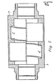
- Fig. 2 einen Längsschnitt durch eine zweite bevorzugte Ausführungsform eines erfindungsgemäßen Wälzringspindeltriebs,
- Fig. 3 einen gegenüber dem Längsschnitt nach Fig. 1 um 90° versetzten Längsschnitt durch den Wälzringspindeltrieb nach Fig. 2,
- Fig. 4 einen den Fig. 1 und 2 entsprechenden Längsschnitt durch eine dritte Ausführungsform eines erfindungsgemäßen Wälzringspindeltriebs,
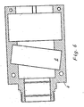
- Fig. 5 einen Längsschnitt durch eine bevorzugte Ausführungsform eines Abtriebsgehäuses eines erfindungsgemäßen Wälzringspindeltriebs,
- Fig. 6 einen gegenüber dem Längsschnitt nach Fig. 5 um 90° versetzten Längsschnitt durch das Abtriebsgehäuse nach Fig. 5,
- Fig. 7 einen Querschnitt durch den Wälzringspindeltrieb nach Fig. 2,
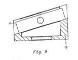
- Fig. 8 einen Längsschnitt durch einen Wälzlageraufnahmekörper des Wälzringspindeltriebs nach Fig. 2,
- Fig. 9 einen gegenüber dem Längsschnitt nach Fig. 8 um 90° versetzten Längsschnitt durch den Gegenstand nach Fig. 8 und
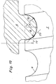
- Fig. 10 einen vergrößerten Ausschnitt aus einem erfindungsgemäßen Wälzringspindeltrieb, der einen Teil des Wälzringes und einen Teil der Antriebsspindel zeigt.
- Die Figuren zeigen einen Wälzringspindeltrieb, zu dem zunächst und im wesentlichen eine Antriebsspindel 1, zwei Wälzlager 2 und ein Abtriebsgehäuse 3 gehören. Dabei sind die Wälzlager 2 als Übertragungsglied zwischen der Antriebsspindel 1 und dem Abtriebsgehäuse 3 wirksam, weisen nämlich die Wälzlager 2 jeweils einen in die Gewindenut 4 der Antriebsspindel 1 eingreifenden Wälzring 5 auf, sind die Wälzlager 2 exzentrisch angeordnet, sind die Mittelachsen 6 der Wälzlager 2 gegenüber der Längsachse 7 der Antriebsspindel 1 geneigt und weist das Abtriebsgehäuse 3 zwei Wälzlageraufnahmen 8 auf.
- Im Ausführungsbeispiel nach Fig. 1 ist der Wälzring 5 als Teil des Innenringes 9 des Wälzlagers 2 an der Innenseite des Innenringes 9 des Wälzlagers 2 ausgebildet. Im Ausführungsbeispiel nach den Fig. 2 bis 4 ist der Wälzring 5 ein separates, mit dem Innenring 9 des Wälzlagers 2 verbundenes Bauteil.
- Die zu dem erfindungsgemäßen Wälzringspindeltrieb gehörenden Wälzlager 2 bestehen, wie üblich, aus dem Innenring 9, aus einem Außenring 10 und aus Wälzkörpern 11, in den dargestellten Ausführungsbeispielen Kugeln.
- Als Mittelachse 6 des Wälzlagers 2 ist die Achse durch den Mittelpunkt des Wälzlagers 2 definiert. Als Wälzlagerlaufebene 12 ist die Ebene definiert, die durch den Mittelpunkt des Wälzlagers 2 geht und auf der die Mittelachse 6 senkrecht steht.
- Der erfindungsgemäße Wälzringspindeltrieb ist nun zunächst dadurch gekennzeichnet, daß jede Wälzlageraufnahme 8 über maximal 180° geht, in den Ausführungsbeispielen exakt über 180° geht. Daraus resultiert, daß jedes Wälzlager 2 senkrecht zu seiner Mittelachse 6, also in der Wälzlagerlaufebene 12, in die zugeordnete Wälzlageraufnahme 8 eingeschoben werden kann. Erfindungsgemäß ist erkannt worden, daß eine rotationssymmetrische, den Außenring 10 des Wälzlagers 2 komplett aufnehmende Wälzlageraufnahme 8 nicht erforderlich ist, daß es zur Aufnahme der von der Antriebsspindel 1 kommenden und über die Wälzlager 2 auf das Abtriebsgehäuse 3 zu übertragenden Kräfte vielmehr ausreicht, wenn jede Wälzlageraufnahme 8 den Außenring 10 des zugeordneten Wälzlagers 2 nur teilweise aufnimmt.
- Bei den Ausführungsbeispielen eines erfindungsgemäßen Wälzringspindeltriebes, die in den Fig 1 bis 4 dargestellt sind, sind innerhalb des Abtriebsgehäuses 3 zwei Wälzlageraufnahmekörper 13 vorgesehen, von denen jeder eine Välzlageraufnahme 8 aufweist.
- Im Gegensatz zu den zuvor beschriebenen Ausführungsbeispielen deuten die Fig. 5 und 6 ein Ausführungsbeispiel eines erfindungsgemäßen Wälzringspindeltriebes an, bei dem das Abtriebsgehäuse 3 selbst mit den Wälzlageraufnahmen 8 versehen ist.
- In den Ausführungsbeispielen nach den Fig. 1 bis 4 sind die Wälzlageraufnahmekörper 13, im Ausführungsbeispiel nach den Fig. 5 und 6 ist das Abtriebsgehäuse 3 in radialer Richtung geteilt. Das ist vorteilhafter, insbesondere in fertigungstechnischer Hinsicht, als eine auch denkbare einteilige Ausführung der Wälzlageraufnahmekörper bzw. des Abtriebsgehäuses. Bei den Ausführungsbeispielen nach den Fig. 1 bis 4 ist dann jeweils nur ein Teil der in radialer Richtung geteilten Wälzlageraufnahmekörper 13 mit der Wälzlageraufnahme 8 versehen. Im Ausführungsbeispiel nach den Fig. 5 und 6 weist jeder Teil des in radialer Richtung geteilten Abtriebsgehäuses 3 eine Wälzlageraufnahme 8 für ein Wälzlager 2 auf.
- Im übrigen zeigen die Figuren insoweit eine bevorzugte Ausführungsform des erfindungsgemäßen Wälzringspindeltriebs, als das Maß der Exzentrizität 14 der Wälzlager 2 einstellbar ist, so daß gleichsam eine Anstellung zwischen Wälzlager 2 und Antriebsspindel 1 möglich ist. Das ist im einzelnen dadurch realisiert, daß die Wälziageraufnahmekörper 13 in radialer Richtung relativ zur Antriebsspindel 1 einstellbar sind. Dazu weist das Abtriebsgehäuse 3 radial verlaufende Gewindebohrungen 15 auf und sind die Wälzlageraufnahmekörper 13 mit Hilfe von in den Gewindebohrungen 15 geführten Stellschrauben 16 radial einstellbar.
- Zuvor ist erläutert worden, daß bei den dargestellten bevorzugten Ausführungsbeispielen des erfindungsgemäßen Wälzringspindeltriebs das Maß der Exzentrizität 14 der Wälzlager 2 einstellbar ist, also eine Möglichkeit der Anstellung zwischen Wälzlager 2 und Antriebsspindel 1 verwirklicht ist. Im übrigen sind in den dargestellten Ausführungsbeispielen auch die Wälzlageraufnahmen 8 in axialer Richtung relativ zur Antriebsspindel 1 einstellbar bzw., was funktionell auf das Gleiche herauskommt, ist die Antriebsspindel 1 in axialer Richtung relativ zu den Wälzlageraufnahmen 8 einstellbar. Dadurch ist auch eine axiale Anstellung zwischen den Wälzlageraufnahmen 8 und der Antriebsspindel 1 möglich.
- Wie sich aus den voranstehenden Ausführungen ergibt, sind nur Ausführungsbeispiele von erfindungsgemäßen Wälzringspindeltrieben dargestellt, die zwei Wälzlager 2 und zwei Wälzlageraufnahmen 8 aufweisen. Dabei ist die zuvor erläuterte Möglichkeit der axialen Anstellung zwischen den Wälzlageraufnahmen 8 und der Antriebsspindel 1 dadurch realisiert, daß die erste Wälzlageraufnahme 8 in axialer Richtung relativ zur Antriebsspindel 1 einstellbar ist und die Antriebsspindel 1 - mittels der ersten Wälzlageraufnahme 8 bzw. mittels des ersten Wälzlagers 2 - in axialer Richtung relativ zur zweiten Wälzlageraufnahme 8 einstellbar ist. Dadurch ist ein Wälzringspindeltrieb mit einem besonders geringen Spiel zwischen der Antriebsspindel 1 und dem Abtriebsgehäuse 3 verwirklicht.
- Im übrigen handelt es sich bei den erfindungsgemäßen Wälzringspindeltrieben, die in den Figuren dargestellt sind, um solche, bei denen die Neigung zwischen den Mittelachsen 6 der Wälzlager 2 und der Längsachse 7 der Antriebsspindel 1 der Steigung der Antriebsspindel 1 im Kraftangriffskreis 17 entspricht. Dabei meint Kraftangriffskreis 17 den Kreis, auf dem die - theoretischen - Kraftangriffspunkte zwischen der Antriebsspindel 1 und den Wälzringen 5 liegen. Das theoretisch Gewollte - Übertragung der Kraft von der Antriebsspindel 1 auf die Wälzringe 5 an einem Kraftangriffspunkt - läßt sich wegen der Elastizität der miteinander in Eingriff kommenden Werkstoffe nicht realisieren, vielmehr ergibt sich stets eine sichelförmige Kraftangriffsfläche. Nun soll konstruktiv sichergestellt werden, daß die tatsächlich wirksame - sichelförmige - Kraftangriffsfläche sich so weit wie möglich dem theoretisch Gewollten, einem Kraftangriffspunkt, annähert. Das ist dadurch erreicht, daß der Krümmungsradius 18 der in die Gewindenut 4 der Antriebsspindel 1 eingreifenden Wälzringe 5 ca. 0,7 bis 0,9 mal so groß wie der Krümmungsradius 19 der Gewindenut 4 der Antriebsspindel 1 sind.
- Weiter ist bei den dargestellten Ausführungsbeispielen von erfindungsgemäßen Wälzringspindeltrieben der Krümmungsradius 18 der in die Gewindenut 4 der Antriebsspindel 1 eingreifenden Wälzringe 5 in Abhängigkeit vom Krümmungsradius 19 der Gewindenut 4 so gewählt, daß im Kraftangriffskreis 10 die Tangente 20 am Wälzring 5 unter ca. 45° zur Längsachse 7 der Antriebsspindel 1 verläuft.
- Schließlich sei noch darauf hingewiesen, daß bei allen dargestellten Ausführungsbeispielen von erfindungsgemäßen Wälzringspindeltrieben die Antriebsspindel 1 über Radiallager 21 im Abtriebsgehäuse 3 gelagert ist.
Claims (14)
Priority Applications (1)
| Application Number | Priority Date | Filing Date | Title |
|---|---|---|---|
| AT84104061T ATE33064T1 (de) | 1983-04-11 | 1984-04-11 | Waelzringspindeltrieb. |
Applications Claiming Priority (2)
| Application Number | Priority Date | Filing Date | Title |
|---|---|---|---|
| DE3313453 | 1983-04-11 | ||
| DE19833313453 DE3313453A1 (de) | 1983-04-11 | 1983-04-11 | Waelzringschraubentrieb |
Publications (2)
| Publication Number | Publication Date |
|---|---|
| EP0122596A1 true EP0122596A1 (de) | 1984-10-24 |
| EP0122596B1 EP0122596B1 (de) | 1988-03-16 |
Family
ID=6196329
Family Applications (1)
| Application Number | Title | Priority Date | Filing Date |
|---|---|---|---|
| EP84104061A Expired EP0122596B1 (de) | 1983-04-11 | 1984-04-11 | Wälzringspindeltrieb |
Country Status (7)
| Country | Link |
|---|---|
| EP (1) | EP0122596B1 (de) |
| JP (1) | JPS60501018A (de) |
| AT (1) | ATE33064T1 (de) |
| BR (1) | BR8406595A (de) |
| DE (2) | DE3313453A1 (de) |
| SU (1) | SU1409137A3 (de) |
| WO (1) | WO1984004143A1 (de) |
Cited By (11)
| Publication number | Priority date | Publication date | Assignee | Title |
|---|---|---|---|---|
| DE3905274A1 (de) * | 1989-02-21 | 1990-08-23 | Gaertner Robert | Spindeltrieb |
| EP0410032B1 (de) * | 1989-07-26 | 1992-10-14 | FAG (Schweiz) | Mutter für Gewindespindel |
| GB2277788A (en) * | 1993-05-06 | 1994-11-09 | Chen Hsi Kuan | Bearing screw and nut assembly |
| DE19515093A1 (de) * | 1995-04-25 | 1996-10-31 | Schaeffler Waelzlager Kg | Schraubgetriebe mit einer Wälzringmutter |
| WO1997001719A1 (de) * | 1995-06-28 | 1997-01-16 | INA Wälzlager Schaeffler oHG | Schraubgetriebe mit einer wälzringmutter |
| WO1997006373A1 (de) * | 1995-08-08 | 1997-02-20 | INA Wälzlager Schaeffler oHG | Schraubgetriebe mit einer wälzringmutter |
| EP0896917A4 (de) * | 1997-02-28 | 2001-07-04 | Koyo Seiko Co | Servosteuersystem |
| US6516680B1 (en) | 1998-10-15 | 2003-02-11 | Koyo Seiko Co., Ltd. | Power steering apparatus |
| EP1884684A3 (de) * | 2006-08-03 | 2010-12-08 | LuK Lamellen und Kupplungsbau Beteiligungs KG | Getriebe zur Umwandlung einer Rotationsbewegung in eine Linearbewegung |
| DE102010007278A1 (de) | 2010-02-08 | 2011-11-17 | Föhrenbach GmbH | Wälzlager und Wälzlageranordnung |
| WO2016181341A1 (en) * | 2015-05-14 | 2016-11-17 | Fondazione Istituto Italiano Di Tecnologia | Linear drive mechanism of the screw and nut type with perfect rolling contact |
Families Citing this family (4)
| Publication number | Priority date | Publication date | Assignee | Title |
|---|---|---|---|---|
| GB8608967D0 (en) * | 1986-04-12 | 1986-05-14 | Jaguar Cars | Mechanical linear actuator |
| US5533417A (en) * | 1993-04-12 | 1996-07-09 | Hughes Aircraft Company | Leadscrew assembly |
| DE102007009626A1 (de) * | 2007-03-03 | 2008-09-04 | Tirron-Elektronik Gmbh | Linearantrieb mit einer Gewindespindel und einer Wälzlagermutter |
| DE102011051514A1 (de) | 2011-07-01 | 2013-01-03 | Wittenstein Ag | Getriebe |
Citations (5)
| Publication number | Priority date | Publication date | Assignee | Title |
|---|---|---|---|---|
| DE1450764A1 (de) * | 1964-08-29 | 1969-04-24 | List Dipl Ing Heinrich | Rollmutter-Verstellwerk mit Vorschub-Spindel |
| US3614900A (en) * | 1970-05-08 | 1971-10-26 | Wahlmark Systems | Anti-friction drive |
| EP0034640A1 (de) * | 1980-02-25 | 1981-09-02 | Robert Dr. Gärtner | Schraubenantrieb |
| DE3012334A1 (de) * | 1980-03-29 | 1981-10-15 | Norco Inc., Georgetown, Conn. | Mechanisches transmissionsgetriebe |
| DE3225495A1 (de) * | 1982-07-08 | 1984-01-12 | AMD-Vertriebsgesellschaft für Antriebstechnik mbH, 5800 Hagen | Schraubengetriebe mit gewindespindel und gewindewaelzmutter |
-
1983
- 1983-04-11 DE DE19833313453 patent/DE3313453A1/de not_active Withdrawn
-
1984
- 1984-04-11 AT AT84104061T patent/ATE33064T1/de not_active IP Right Cessation
- 1984-04-11 WO PCT/DE1984/000088 patent/WO1984004143A1/de not_active Ceased
- 1984-04-11 JP JP59501592A patent/JPS60501018A/ja active Pending
- 1984-04-11 EP EP84104061A patent/EP0122596B1/de not_active Expired
- 1984-04-11 DE DE8484104061T patent/DE3469948D1/de not_active Expired
- 1984-04-11 BR BR8406595A patent/BR8406595A/pt unknown
- 1984-12-10 SU SU843828179A patent/SU1409137A3/ru active
Patent Citations (5)
| Publication number | Priority date | Publication date | Assignee | Title |
|---|---|---|---|---|
| DE1450764A1 (de) * | 1964-08-29 | 1969-04-24 | List Dipl Ing Heinrich | Rollmutter-Verstellwerk mit Vorschub-Spindel |
| US3614900A (en) * | 1970-05-08 | 1971-10-26 | Wahlmark Systems | Anti-friction drive |
| EP0034640A1 (de) * | 1980-02-25 | 1981-09-02 | Robert Dr. Gärtner | Schraubenantrieb |
| DE3012334A1 (de) * | 1980-03-29 | 1981-10-15 | Norco Inc., Georgetown, Conn. | Mechanisches transmissionsgetriebe |
| DE3225495A1 (de) * | 1982-07-08 | 1984-01-12 | AMD-Vertriebsgesellschaft für Antriebstechnik mbH, 5800 Hagen | Schraubengetriebe mit gewindespindel und gewindewaelzmutter |
Cited By (15)
| Publication number | Priority date | Publication date | Assignee | Title |
|---|---|---|---|---|
| DE3905274A1 (de) * | 1989-02-21 | 1990-08-23 | Gaertner Robert | Spindeltrieb |
| EP0410032B1 (de) * | 1989-07-26 | 1992-10-14 | FAG (Schweiz) | Mutter für Gewindespindel |
| GB2277788A (en) * | 1993-05-06 | 1994-11-09 | Chen Hsi Kuan | Bearing screw and nut assembly |
| DE19515093A1 (de) * | 1995-04-25 | 1996-10-31 | Schaeffler Waelzlager Kg | Schraubgetriebe mit einer Wälzringmutter |
| US5956997A (en) * | 1995-06-28 | 1999-09-28 | Ina Walzlager Schaeffler Ohg | Worm gear with a gear ring nut |
| WO1997001719A1 (de) * | 1995-06-28 | 1997-01-16 | INA Wälzlager Schaeffler oHG | Schraubgetriebe mit einer wälzringmutter |
| WO1997006373A1 (de) * | 1995-08-08 | 1997-02-20 | INA Wälzlager Schaeffler oHG | Schraubgetriebe mit einer wälzringmutter |
| US6053063A (en) * | 1995-08-08 | 2000-04-25 | Ina Walzlager Schaeffler Ohg | Worm drive with a roller ring nut |
| EP0896917A4 (de) * | 1997-02-28 | 2001-07-04 | Koyo Seiko Co | Servosteuersystem |
| KR100565400B1 (ko) * | 1997-02-28 | 2006-10-31 | 가부시키가이샤 제이텍트 | 동력 조향장치 |
| US6516680B1 (en) | 1998-10-15 | 2003-02-11 | Koyo Seiko Co., Ltd. | Power steering apparatus |
| EP1884684A3 (de) * | 2006-08-03 | 2010-12-08 | LuK Lamellen und Kupplungsbau Beteiligungs KG | Getriebe zur Umwandlung einer Rotationsbewegung in eine Linearbewegung |
| DE102010007278A1 (de) | 2010-02-08 | 2011-11-17 | Föhrenbach GmbH | Wälzlager und Wälzlageranordnung |
| WO2016181341A1 (en) * | 2015-05-14 | 2016-11-17 | Fondazione Istituto Italiano Di Tecnologia | Linear drive mechanism of the screw and nut type with perfect rolling contact |
| US10364871B2 (en) | 2015-05-14 | 2019-07-30 | Fondazione Istituto Italiano Di Technologia | Linear drive mechanism of the screw and nut type with perfect rolling contact |
Also Published As
| Publication number | Publication date |
|---|---|
| BR8406595A (pt) | 1985-03-12 |
| EP0122596B1 (de) | 1988-03-16 |
| JPS60501018A (ja) | 1985-07-04 |
| ATE33064T1 (de) | 1988-04-15 |
| DE3313453A1 (de) | 1984-10-31 |
| WO1984004143A1 (en) | 1984-10-25 |
| SU1409137A3 (ru) | 1988-07-07 |
| DE3469948D1 (en) | 1988-04-21 |
Similar Documents
| Publication | Publication Date | Title |
|---|---|---|
| EP0122596B1 (de) | Wälzringspindeltrieb | |
| DE3421273C2 (de) | Wellenbuchseneinheit | |
| DE102008051544B4 (de) | Spindeltrieb mit Verdrehsicherung | |
| DE19526727B4 (de) | Kugelumlaufvorrichtung mit externem Umlauf | |
| DE3416207A1 (de) | Linear-kugellageranordnung | |
| EP0622157A1 (de) | Werkzeugeinspannschaft | |
| DE102019125310A1 (de) | Planetenwälzgetriebe | |
| EP0849078A1 (de) | Vorrichtung zur Vermeidung von Spiel zwischen den kämmenden Zähnen eines ersten und eines zweiten Zahnrads in einem Druckwerk einer offset-Rotationsdruckmaschine | |
| EP1348077A1 (de) | Kältemittelverdichter | |
| DE3038774C2 (de) | Schraubtrieb mit Doppelmutter | |
| DE102019117227A1 (de) | Spielfreies Planetenradgetriebe | |
| DE69617234T2 (de) | Stellantrieb für lineare bewegung | |
| DE60026961T2 (de) | Transmissions- und Drehmomentbegrenzungs-Kupplung, die antreibende und angetriebene Teile immer in einer einzigen Winkelposition ergreifen kann | |
| WO2019179934A1 (de) | Untersetzungsgetriebe sowie getriebemotor | |
| DE68901835T2 (de) | Arretiersystem. | |
| EP4084932A1 (de) | Federspanner | |
| EP1078178B1 (de) | Exzenterzahnradgetriebe | |
| DE102020213365A1 (de) | Exzentergetriebe für einen Bremskrafterzeuger, Bremskrafterzeuger | |
| DE2727623A1 (de) | Halterung fuer ein drehlager | |
| DE3000477A1 (de) | Wellen-kreuzgelenk, insbesondere fuer eine exzenter-schneckenpumpe | |
| EP1637771A2 (de) | Gewindetrieb | |
| EP0753683A2 (de) | Scheibenbremse | |
| EP0139974A1 (de) | Lageranordnung mit einem selbsteinstellenden Kalottenlager | |
| DE2815026C2 (de) | Nachspannendes Bohrfutter | |
| DE19650716C1 (de) | Exzentergetriebe |
Legal Events
| Date | Code | Title | Description |
|---|---|---|---|
| PUAI | Public reference made under article 153(3) epc to a published international application that has entered the european phase |
Free format text: ORIGINAL CODE: 0009012 |
|
| AK | Designated contracting states |
Designated state(s): AT BE CH DE FR GB IT LI LU NL SE |
|
| 17P | Request for examination filed |
Effective date: 19850302 |
|
| 17Q | First examination report despatched |
Effective date: 19860206 |
|
| GRAA | (expected) grant |
Free format text: ORIGINAL CODE: 0009210 |
|
| AK | Designated contracting states |
Kind code of ref document: B1 Designated state(s): AT BE CH DE FR GB IT LI LU NL SE |
|
| PG25 | Lapsed in a contracting state [announced via postgrant information from national office to epo] |
Ref country code: NL Effective date: 19880316 Ref country code: IT Free format text: LAPSE BECAUSE OF FAILURE TO SUBMIT A TRANSLATION OF THE DESCRIPTION OR TO PAY THE FEE WITHIN THE PRESCRIBED TIME-LIMIT;WARNING: LAPSES OF ITALIAN PATENTS WITH EFFECTIVE DATE BEFORE 2007 MAY HAVE OCCURRED AT ANY TIME BEFORE 2007. THE CORRECT EFFECTIVE DATE MAY BE DIFFERENT FROM THE ONE RECORDED. Effective date: 19880316 Ref country code: FR Free format text: THE PATENT HAS BEEN ANNULLED BY A DECISION OF A NATIONAL AUTHORITY Effective date: 19880316 Ref country code: BE Effective date: 19880316 |
|
| REF | Corresponds to: |
Ref document number: 33064 Country of ref document: AT Date of ref document: 19880415 Kind code of ref document: T |
|
| PG25 | Lapsed in a contracting state [announced via postgrant information from national office to epo] |
Ref country code: SE Effective date: 19880331 |
|
| PG25 | Lapsed in a contracting state [announced via postgrant information from national office to epo] |
Ref country code: AT Effective date: 19880411 |
|
| REF | Corresponds to: |
Ref document number: 3469948 Country of ref document: DE Date of ref document: 19880421 |
|
| PG25 | Lapsed in a contracting state [announced via postgrant information from national office to epo] |
Ref country code: LU Free format text: LAPSE BECAUSE OF NON-PAYMENT OF DUE FEES Effective date: 19880430 Ref country code: LI Effective date: 19880430 Ref country code: CH Effective date: 19880430 |
|
| EN | Fr: translation not filed | ||
| NLV1 | Nl: lapsed or annulled due to failure to fulfill the requirements of art. 29p and 29m of the patents act | ||
| GBV | Gb: ep patent (uk) treated as always having been void in accordance with gb section 77(7)/1977 [no translation filed] | ||
| PG25 | Lapsed in a contracting state [announced via postgrant information from national office to epo] |
Ref country code: GB Free format text: LAPSE BECAUSE OF NON-PAYMENT OF DUE FEES Effective date: 19881122 |
|
| REG | Reference to a national code |
Ref country code: CH Ref legal event code: PL |
|
| PG25 | Lapsed in a contracting state [announced via postgrant information from national office to epo] |
Ref country code: DE Effective date: 19890103 |
|
| PLBE | No opposition filed within time limit |
Free format text: ORIGINAL CODE: 0009261 |
|
| STAA | Information on the status of an ep patent application or granted ep patent |
Free format text: STATUS: NO OPPOSITION FILED WITHIN TIME LIMIT |
|
| 26N | No opposition filed |