EP0122573A2 - Kit for the construction of belt conveyor arrangements - Google Patents
Kit for the construction of belt conveyor arrangements Download PDFInfo
- Publication number
- EP0122573A2 EP0122573A2 EP84103920A EP84103920A EP0122573A2 EP 0122573 A2 EP0122573 A2 EP 0122573A2 EP 84103920 A EP84103920 A EP 84103920A EP 84103920 A EP84103920 A EP 84103920A EP 0122573 A2 EP0122573 A2 EP 0122573A2
- Authority
- EP
- European Patent Office
- Prior art keywords
- holes
- longitudinal
- frame
- spars
- kit according
- Prior art date
- Legal status (The legal status is an assumption and is not a legal conclusion. Google has not performed a legal analysis and makes no representation as to the accuracy of the status listed.)
- Granted
Links
Images

Classifications
-
- B—PERFORMING OPERATIONS; TRANSPORTING
- B65—CONVEYING; PACKING; STORING; HANDLING THIN OR FILAMENTARY MATERIAL
- B65G—TRANSPORT OR STORAGE DEVICES, e.g. CONVEYORS FOR LOADING OR TIPPING, SHOP CONVEYOR SYSTEMS OR PNEUMATIC TUBE CONVEYORS
- B65G21/00—Supporting or protective framework or housings for endless load-carriers or traction elements of belt or chain conveyors
- B65G21/10—Supporting or protective framework or housings for endless load-carriers or traction elements of belt or chain conveyors movable, or having interchangeable or relatively movable parts; Devices for moving framework or parts thereof
- B65G21/14—Supporting or protective framework or housings for endless load-carriers or traction elements of belt or chain conveyors movable, or having interchangeable or relatively movable parts; Devices for moving framework or parts thereof to allow adjustment of length or configuration of load-carrier or traction element
-
- B—PERFORMING OPERATIONS; TRANSPORTING
- B65—CONVEYING; PACKING; STORING; HANDLING THIN OR FILAMENTARY MATERIAL
- B65G—TRANSPORT OR STORAGE DEVICES, e.g. CONVEYORS FOR LOADING OR TIPPING, SHOP CONVEYOR SYSTEMS OR PNEUMATIC TUBE CONVEYORS
- B65G21/00—Supporting or protective framework or housings for endless load-carriers or traction elements of belt or chain conveyors
- B65G21/02—Supporting or protective framework or housings for endless load-carriers or traction elements of belt or chain conveyors consisting essentially of struts, ties, or like structural elements
- B65G21/06—Supporting or protective framework or housings for endless load-carriers or traction elements of belt or chain conveyors consisting essentially of struts, ties, or like structural elements constructed to facilitate rapid assembly or dismantling
Definitions
- the invention relates to a kit for creating belt conveyor devices in the form of single or multi-belt or belt conveyors or hinged belt conveyors.
- the invention is therefore based on the object to provide a way, while avoiding the disadvantages of known belt conveyor devices even with untrained and even inexperienced, possibly trained personnel, quickly and conveniently and yet particularly cost-effectively both with regard to the purchase price and the degree of use and in particular also of the storage effort itself, even short-term changes in the funding to be able to adapt conditions in a conveyor line or a material flow system so that a universality of the adaptation options that reliably satisfies practically all expected funding conditions is guaranteed, despite and with a minimum of machine and mantage expenditure to be maintained, and production and / or distribution interruptions with the dreaded failure or failure Funding dead times and costs are largely eliminated.
- the invention proposes for the first time a kit for the creation of belt conveyor devices in the form of single or multi-belt or belt conveyors or hinged belt conveyors, which is characterized by at least one pair in each known manner as a U or C profile trained frame longitudinal spars, which have a flat bottom web and a plurality of holes arranged in the same on its center line in a line grid and at least in or at least transversely to the direction of the grid line of the same hole size, corresponding to at least one unreduced number of pairs of frame longitudinal spars Number of connecting elements or pairs of the same, each with a fastening flange which protrudes approximately normally on both sides and which has at least two holes of approximately the same size as that of the longitudinal frame bars provided in the grid arrangement of the holes in the longitudinal frame bars, at least one pedestal with connecting flanges which are arranged in a spacing corresponding to one another in the assembled state to the dimension between the outer surfaces or between the longitudinal frame bars opposite the inner surfaces, which likewise
- Roller holder device with a pair of delivery roller supports that can be supported in each case on an associated frame longitudinal beam, a conveying means in the form of a belt or belt or several of the same or a hinge belt and a number of feed rollers and delivery rollers corresponding to the number of belts or belts or hinge belts and one of the number of im
- corresponding holes in the components to be fastened to one another correspond to the corresponding number of screw connections, preferably consisting of screw bolts, nuts with washers and lock nuts.
- Such longitudinal frame profiles can be screwed to other components of the belt conveyor device to be created without the interposition of fittings, however, such belt conveyor devices have hitherto been produced exclusively in the manufacturer's factory, with particular attention to the individual needs of the individual user previously determined coordinated properties of the same, in particular with regard to the dimensions of the frame, especially with regard to the required length.
- the invention provides the further advantage that the individual parts of the kit according to the invention, which are specifically adapted for assembly and with one another, can be offered and delivered in permanent packaging containers which later open up the desired possibility for the user to conveniently remove a dismantled belt conveyor device in this, Space-saving and cost-effective storage in every respect until it is needed again.
- the conception of a kit according to the invention gives the purchaser the further possibility offers to create not only a belt conveyor device of a desired design, but such a belt conveyor device should it no longer be needed at a certain point in a material flow system, but in a similar or different functional configuration it should be useful at another point in this or another material flow system can be quickly and inexpensively adapted to the new desired application by simple retrofitting.
- a particularly simple example of such an adaptation is, for example, the retrofitting of a belt conveyor device created from a specific number of pairs of longitudinal frame spars of the kit according to the invention to a shorter or longer length required at another place of use.
- belt conveyor devices can not only be made available at a particularly attractive cost price, since their individual parts can be mass-produced in the manufacturer's plant or, as usually even standardized machine elements, can be purchased at any time with practically no delivery difficulties, but also that The user of such a kit according to the invention is given a hitherto unknown universality of adaptation options to the most varied of funding conditions, which despite its great variability also only requires a minimum of capital commitment.
- At least one connecting element designed as a U-shaped sheet metal trough according to claim 3 can also be expediently provided. This can preferably be used as accident protection for the running gap of the lower run of the conveying means in the area of the feed roller (s) and / or the discharge roller (s), if desired.
- a connecting element in the form of a U-shaped sheet metal trough is given a length according to claim 4, it can be used specifically to increase the bending and torsional rigidity of the entire frame structure, the desired effect here being able to be influenced by a corresponding choice of the number of screw connections .
- a connecting element is given a length according to claim 5, it can be used expediently as the joint between two pairs of longitudinal frame spars, particularly when creating belt conveyors with a frame formed from a plurality of pairs of longitudinal frame spars.
- kit according to claim 7 For heavier versions of belt conveyor devices, a version of the kit according to claim 7 is recommended, which takes into account a special stability designed for higher loads on the frame.
- stand stands with cross bars carrying the conveyor belt frames are provided.
- Its fixation device can either be designed as a footplate or as a stool, which can preferably be moved and / or height-adjustable relative to the cross member.
- a height adjustability can be provided by telescopically telescoping at least two parts of the pillars of at least one pair of pillars or at least one of the individual pillars provided, regardless of whether the conveyor belt frame is provided by paired feet or individually Stands with corresponding crossbeams supporting it can be designed in a further expedient training to facilitate assembly of the kit according to the invention according to claim 12, in particular inclined band arrangements with increasing or decreasing funding are possible.
- the feed roller (s) or the discharge roller (s) can advantageously be designed as a drive roller (s).
- the kit can preferably be designed such that the roller carriers of the feed or discharge roller (s) serving as drive roller (s) can be fixed to the frame according to claim 15.
- the kit according to the invention is designed in such a way that the roller carriers of the feed roller (s) and / or the roller carriers of the discharge roller (s) are adjustable in relation to the conveyor belt frame and can be determined in the desired working position.
- This embodiment of the invention has the advantage that not only can readjustments of the working tension of the conveying means (e.g. belt tension) be achieved in this way, which could also be achieved in a different way, but - which is of much greater importance - local adjustments to the positional assignment of the takeover -and / or the transfer point of the belt conveyor for the material to be conveyed from the upstream conveyor unit or to the downstream conveyor unit.
- An embodiment of a kit for this purpose which is particularly simple in terms of construction and production technology and is particularly reliable in operation, results from claim 17.
- At least one deflection device for the conveying means each with a pair of bearing supports for the axes of one or more reversing rollers (s) for the lower or the upper run of the conveying means and one or more hold-down rollers for the other run, each of which has two legs, one of which can be supported on a longitudinal frame beam and the other on the longitudinal frame beam following in the conveying direction.
- a structurally and technically particularly simple and correspondingly inexpensive embodiment of this inventive idea results according to claim 22.
- a certain angular dimension of the change in inclination from one branch to the other can be achieved with a kit according to the According to experience, there are important reasons, both operationally and from an investment point of view, to be able to keep the conveying tendency variable from one branch to the other with a belt conveyor device created according to the invention, whereby this is done as far as possible should even be possible during the conveyor operation.
- This object is achieved according to claim 23 in that the legs of the two bearing brackets of at least one deflection device can be changed in their angular position relative to one another.
- the kit can advantageously be designed in a further development of the invention.
- an alternative has also proven particularly useful, both for constructional and for manufacturing reasons, in which the bearing supports are designed according to claim 25.
- kit according to claim 28 is provided and equipped for the provision of at least one slide bar, preferably a pair of such bars.
- kits according to the invention which has been perfected according to claim 29, provides the possibility for a feed hopper.
- a kit according to the invention in further perfection according to claim 3o can also offer the possibility for a delivery chute.
- a possibility for the use of a transition chute according to claim 31 can also be of considerable advantage.
- a kit according to the invention in contrast to bulk goods, it may be preferable in particular for piece goods to be conveyed if, instead of a feed and / or discharge hopper, a kit according to the invention, in particular in the interest of increasing the universality of its possible uses according to claim 32, for the production of a belt conveyor with at least one Feed wall and / or at least one delivery wall, preferably in each case a pair of such delivery walls.
- a transition barrier wall preferably a pair of such transition barrier walls, can advantageously also be provided for the same purpose.
- the kit can be designed according to claim 35 in a further advantageous development of the invention.
- a pair of longitudinal frame spars 2 made of C-profile material with a flat base web 2a and parallel to it or slightly inclined to this edge webs 2b is provided.
- These longitudinal frame spars have on the center line m of their base web 2a a multiplicity of holes 3 arranged at the same distance from one another, which are formed here as round holes, but could also be formed, for example, as elongated holes with the same size in or at least transverse to the direction of the grid line m.
- connection of the cross bars 4 to the frame longitudinal bars 2 to be connected on both sides screw connections 28 are provided, which can preferably consist of screw bolts, nuts with washers and, if necessary, lock nuts.
- the conveyor belt frame thus formed of the belt conveyor device designated as a whole by 1 is supported by a pair of feet 9, each of which is formed from a pair of pillars 32 which are connected to one another by two cross bars 45, which, like the cross bars 4, are sections of a round tube - or rectangular - tubular material can be formed and at the ends of each connection flanges 46 are fixed, for example by welding, which have holes 46 which are aligned with corresponding holes in the pillars 32, so that by means of screw connections 85 a rigid and torsionally rigid base 9 made of pillars 32 and cross bars 45 can be formed.
- the pillars 32 can either be formed in one piece, as shown in the right pedestal 9, or can be composed of several sections 32a, 32b, 32c, which can be telescopically inserted into one another, as in the case of one pillar of the left stand 9 shown.
- the pillars can be made of rectangular tube and / or of another profile material, such as a C-profile 32c, as shown.
- insertable tabs 86 can be provided in the interior thereof, which serve as clamping plates or abutments for corresponding screw connections which are indicated but not shown in detail.
- An embodiment with pillars 32 formed from at least two parts which can be telescoped against one another will always be provided where it is necessary to change the inclination of the belt conveyor device 1 without exchanging the feet 9 for others.
- the pillars 32 themselves have base plates 43 at their lower ends.
- swivel flanges 47 are provided, one of which is assigned to a support pillar 32 and along its upper edge a number of holes 48 of approximately the same size as that of the holes 3 of the longitudinal spars 2, which are provided in the same grid arrangement as the latter, so that the swivel flanges 47 also preferably with existing screw bolts, nuts with washers and lock nuts 28 at any suitable location of the frame longitudinal spars 2 can be.
- the swivel flanges 47 each further have a hole 49 and an arcuate slot 50 concentric to this, the radius of curvature the same corresponding distance to the center hole 49 corresponds to the distance between two flange holes 13 in a respective connection flange 11 which can be fixed by screwing at the upper end of each pillar 32.
- a screw bolt 51 serving as a swivel bearing extends through, which can be fixed by means of a nut with a washer and optionally a lock nut, if necessary with the aid of a clamping plate.
- a locking screw 52 extends, by means of which the swivel flange 47 and with it the conveyor belt frame can be fixed in any swivel position that corresponds to the length of the circular arc slot.
- a feed roller 20 with an axis 21 is provided which is practically continuous over the entire width of the conveyor belt frame, although with the interposition of.
- the spacer rings and washers shown, but not described in more detail, are supported by a pair of roller carriers 15, each of which has an end piece 17 on its side remote from the feed roller shaft or axis, which is contoured in such a way that it can be inserted into the profile cavity of the associated longitudinal frame profile 2 is.
- the shaft supports 15 also each have a nose 16 with a threaded hole, which is shown but not described in more detail, into which a threaded pin 19 of a tensioning device formed by this and the nose 16 with its threaded hole for the feed roller axis 21 can be screwed in and not by means of a screw however specified lock nut in any desired working
- the position of the threaded pin with its free end can be in contact with the feed roller axis 21 directly or with the interposition of a pressure piece (not shown) which can be rotated relative to it.
- the threaded pin 19 has at its free end a fixedly arranged receiving ring for the feed roller axis 21, which can rotate in this or, if the entire feed roller arrangement 20, 21 is designed as a thru-axle arrangement, not by means of an illustrated one however specified screw, which penetrates the receiving ring via a threaded hole in it, can be fixed on this in a rotationally fixed manner.
- the hole in the nose 16 of the roller carrier 15 is not designed as a threaded hole, but rather as a push-through hole for the threaded pin 9, which is simply inserted into it.
- the center distance of the feed roller axis 21 from the front end of the associated frame longitudinal beam profile 2, against which the nose 16 of the roller carrier 15 inserted in its profile cavity with its end piece 17 is in contact, is activated by actuating the adjusting nut of the setscrew 19, which is shown but not described in more detail set and fixed in any desired working position.
- the end pieces 17 of the roller carriers 15 each have a pocket slot 18 arranged symmetrically to the grid line m (center line of the bottom web 2a of the frame longitudinal beam profiles 2 and preferably also the end pieces 17 of the roller carriers 15) in the assembled state.
- fixation is then carried out by means of at least two screw holes 28 penetrating through holes 3 in the frame spars 2 and the blind slot 18 of the roller carrier 15 inserted into its profile cavity, if necessary with the aid of a clamping plate 30, wherein here, too, these screw connections 28 can preferably consist of a screw bolt and nut with washer and, if appropriate, a lock nut.
- a support horn 64 can also be defined at the same time, which has along its upper edge at least two holes 65 of approximately the same size as that of the holes 3 of the longitudinal frame members in the grid arrangement of the same corresponding arrangement.
- such a support horn which is preferably provided in pairs on both longitudinal frame spars 2, can also be fixed at another location and independently of the fixing of the roller carrier 15 to the longitudinal frame spar 2.
- a delivery roller 40 which is also continuous over practically its entire width, is supported with its shaft 41 with the interposition of bearings, which are shown but not described in more detail, in a pair of delivery roller carriers 35, each of which has an end piece 37 on its side remote from the delivery roller , with which they are inserted in the main assembly into the profile cavity of the associated longitudinal spar 2, against the end of which they are supported with a nose 36.
- the discharge roller 40 in the illustrated embodiment is designed as a drive roller for the conveying means moving in the conveying direction F, stretched over it and the feed roller 20 in the form of a belt 27, the discharge roller carriers 35 thus serving as drive roller carriers, unlike the feed roller carriers 15, have no open to the outside Opening mouth for the shaft or axis in question, but a closed bearing mounting, as shown.
- the end pieces 37 of the roller carriers 35 are provided with a blind slot 38 in the same way as for the end pieces 17 of the roller carriers 15 described above.
- the roller supports 35 are fixed to the associated longitudinal beam profiles 2 in the same way as already described in connection with the feed roller supports 15 by means of screw connections 28, if necessary with the aid of a clamping plate 30.
- the nose 36 has its W a l-center support 35 has a threaded hole into which a threaded pin 39 is screwed, which is supported with its end on the side of the frame side member on a corresponding stop surface on the side member 2, such as a support bracket 94 pushed in addition to the end piece 37 of the roller member 35 in its profile cavity and determined by more or less screwing in the axial position of the output roller shaft 41 relative to the end face of the associated longitudinal frame spar 2.
- a bearing plate 24 for a drive motor 22 is also fixed on a longitudinal frame 2, by means of holes 26 of approximately the same size as holes 3 in the longitudinal frame 2, which are provided by holes 28 in the grid arrangement of the holes 3 in the longitudinal frame 2 corresponding arrangement, which likewise again preferably consisting of a screw bolt, a nut with a washer and, if necessary, a lock nut, if necessary additionally a clamping plate 30.
- the drive pinion of a kinematic drive chain block 23 designed as a chain drive is wedged onto its output shaft, the drive pinion of which is designed but is not designated in greater detail, the output pinion of which is connected in a rotationally fixed manner to the shaft 41 of the output roller 40 functioning as the drive shaft.
- the tensioning device 36, 39 for the delivery roller 40 also simultaneously receives the function of a tensioning device for the kinematic drive chain hoist 23, by means of which its chain tensioning can be brought to the desired level, although of course not the function of the tensioning device 36, 39 which is also present It may be overlooked that the entire belt conveyor device 1 should be adapted in terms of its delivery point, if necessary, to a downstream conveyor unit that may be present.
- the two sections 86 and 87 of the chain case covering the chain drive 23 are also shown with their associated screw connections, one of which can engage on the end face in a blind hole (not shown) of the roller carrier 35.
- the control panel 79 is fixed to this end shield 80 by means of screw connections 83 which extend through further holes 82.
- FIG. 1 shows the one end shields of two pairs of end shields 95 for guide rollers 97 for the lower run of the conveying means 27, each of which has a receiving bore 98 for the axis of the associated guide roller 97 and along its upper edge in each case at least two in the grid arrangement of the holes 3 of the longitudinal frame spars 2 corresponding to the arrangement have holes 96 of approximately the same size as that of the holes 3 of the longitudinal frame spars 2, via which they with the longitudinal frame spars 2 by means of screws, nuts with washers and, if applicable, lock nuts of existing screw connections 28 (not shown) can be connected to any position deemed desirable or necessary.
- Fig. 1 also shows a feed hopper 71, which can be composed of several sections 71a, 71b and is to be arranged at the feed point for the material to be conveyed above the conveyor belt frame by the lower regions of its sections 71a assigned to the longitudinal frame members 2 (only one of which is shown) each have holes 74 provided in the arrangement of the holes 3 of the frame longitudinal spars 2 corresponding to the arrangement ; through which it by means of encryption - screw connections 28, which also with advantage of bolts, may be made nut with washer and optionally the lock nut, may be connected in the manner already described to the associated frame longitudinal member 2, so that the entire feed hopper 71 by the two opposite frame longitudinal beams 2 will be carried.
- a feed hopper 71 which can be composed of several sections 71a, 71b and is to be arranged at the feed point for the material to be conveyed above the conveyor belt frame by the lower regions of its sections 71a assigned to the longitudinal frame members 2 (only one of which is shown) each have holes 74 provided in the
- the end part 71b of the receiving funnel 71 can carry a cover plate 72 for the feed roller 20, in that this is fixed to the component 71b by means of a clamping strip 73, namely screw connections, which are shown but not described in more detail.
- a Feed hopper 71 will be preferred as bulk material for bulk goods. If piece goods are to be handled as goods to be conveyed, it is usually advisable to use a loading plate (not shown) as a lateral limitation of the point of delivery for the goods to be conveyed.
- the exemplary embodiment of a kit according to the invention according to FIG. 1 further provides side limitation strips 66 for the conveyed goods conveyed on the upper run of the conveying means 27, only one of which is shown. As indicated, it is designed as an angular profile, and holes 67 are provided in its downward-pointing flange. If this downward-pointing flange of the side delimitation bar 66 has a sufficient width, it can be provided for fastening the side delimitation bar 66 directly to the associated frame longitudinal bar 2 by arranging the holes 67 in a plurality and in a grid arrangement of the holes 3 in the frame longitudinal bar 2, as well as with approximately the same size of the holes 3 of the longitudinal frame members 2 are provided.
- the fixing to the longitudinal frame spars 2 is then carried out in the manner already described by means of screw connections 28.
- the holes 67 can be provided in the same or a different arrangement.
- at least one pair of support flanges 68 is provided for each side delimitation strip 66, only one of which is shown.
- These then have holes 69 which are arranged in accordance with the arrangement of the holes 67 and via which the support flange 68 can be connected to the side delimitation strip 66.
- each support flange 68 also has at least two holes 70 of approximately the same size as the holes 3 of the longitudinal frame spars 2 provided in the grid arrangement of the holes 3 of the longitudinal frame spars, via which the support flange 68 in the manner already described many times above by means of screw connections 28 (not shown) on the associated longitudinal frame spar 2 so can be determined that the side delimitation bar 66 assumes its working position in the correct assignment to the upper run of the conveyor 27.
- a support plate 88 can be provided, which is supported by the conveyor belt frame by resting along its two marginal edges on a support bar 90 which, with the interposition of a spacer bar 89 ensuring sufficient running clearance for the upper run of the conveyor 27, by means of screw connections 91 from below on the Upper side web of the longitudinal frame profile 2 and / or preferably the central region of the profile of the side delimitation bar 66 lying parallel to this is screwed.
- FIG. 2 The embodiment according to FIG. 2 is carried out essentially in the same way as that according to FIG. 1, so that reference can be made to the above description of the latter and only details of the embodiment according to FIG. 2 which differ from this are explained in more detail below.
- edge webs 5b In the edge webs 5b at least two holes 7 of approximately the same size as that of the holes 3 of the longitudinal beams 2 with their grid arrangement corresponding arrangement are provided so that the respective connecting element 5 can be inserted into the assembly of the conveyor belt frame by means of screw connections 28 in a manner already described many times above can.
- the length 1 of the U-groove-shaped connecting element 5 can correspond approximately to the length of the frame longitudinal bars 2.
- the transverse members 4 are unnecessary, since by such a connecting member 5 to the conveyor andrahmen b a considerably larger bending and / or torsional rigidity is imparted.
- the cross bars 4 are also dispensable when using connecting elements 5, but with a shorter length 1.
- a U-shaped connecting element 5 can also be used in such a way that it also serves as protection against tampering in order to comply with accident prevention regulations serves for the area of the lower run of the conveying means 27 on the feed or discharge roller side.
- connecting elements 5 can expediently also be used as connecting bridges bridging the joints between two successive pairs of longitudinal frame spars 2.
- the stand 8 supporting the entire belt conveyor device 1 is provided.
- This has a single central pillar 31, which is guided telescopically with its lower end and is vertically adjustable in a movable footrest 42 by means of a locking device, which is shown but not described in more detail, and carries crossbar 44 at its stool-remote end, for example, at its two ends by means of welding, a connecting flange 10 is fixed, the two connecting flanges being at a distance from one another which corresponds to the distance between the inner surfaces or between the outer surfaces of two longitudinal frame spars 2 located opposite in the assembled state. These each have two flange holes 12 arranged one above the other.
- the holes 12 in the connecting flanges 10 can also be designed in the grid arrangement of the holes 3 of the longitudinal frame spars 2 in a corresponding arrangement and with approximately the same size, so that the base over the connecting flanges 10 of the cross member 44 of its pillar 31 can be connected directly to the longitudinal frame members 2. If, on the other hand, an adjustability of the conveying inclination is desired, the flange holes 12 in the arrangement shown are carried out at the same distance as that of the circular-shaped slot from its center hole 49 in the swivel flange 47 shown, and the connection of the base 8 takes place via the connecting flanges 10 in the same way, as already described in connection with FIG. 2 with regard to the connection of the connecting flanges 11 of the feet 9.
- FIG. 2 Since the embodiment of the invention according to FIG. 2 is an articulated belt conveyor, it has two pairs of longitudinal frame bars 2, which are in the area the kink are connected via a deflection device, designated as a whole as 53, to bearing supports 54 provided in pairs, each of which has two legs 55a, 55b and whose angular assignment to one another can be changed by means of screw connections 84 which pass through mutually aligned holes in them and in the desired manner Angular position to each other are stable.
- a deflection device designated as a whole as 53
- Both legs 55a, 55b of each bearing bracket 54 each have an end piece 57a or 57b which can be inserted into the profile cavity of the adjacent longitudinal frame member 2, each with a pocket slot 58a or 58b which extends symmetrically to the grid line m of the associated longitudinal frame member 2, which is already in connection with the roller carriers of the feed roller 20 or the output roller 40 according to FIG. 1 in the manner described by means of screw connections 28 if necessary. with the aid of clamping plates 30 can be fixed to the associated longitudinal frame beam 2.
- the holder of the feed roller 20 at the free end of the longitudinal frame pair shown at the bottom right is the same as that already described in connection with FIG. 1.
- the task roller-side legs 55b each have a mounting for hold-down rollers 62 for the upper run of the conveying means 27 in the form of axes formed by screw bolts 63, which are screwed together with an upwardly extending tab of this leg 55b.
- the other legs 55a support the axle 61 of a deflection roller 60 for the lower run of the conveying means 27 in the same way as the feed roller 20 is mounted in its roller carriers 15.
- the mode of operation of the nose 56a on the Leg 55a and the screw device 59a formed of the deflection device 53 for the deflection roller 60 is the same as that of the tensioning device 16, 19 for the feed roller 20.
- the standing flange thereof extending laterally away from the lower end of the lateral sections 71a also serves to support a sliding plate 92 which supports the upper run of the conveying means 27 in the region of the feed point for the conveyed material from its underside by means of a not shown supporting bar.
- a sliding plate 88 is held under the upper run of the conveying means 27, but is not shown in FIG. 2.
- a pair of delivery walls 74 are arranged, only one of which is shown in FIG. 2. It is designed as a run-shaped, bent sheet metal blank and has in its downward-facing flange a number of holes 75 of approximately the same size as the holes 3 of the longitudinal frame spars 2, arranged in the grid arrangement of the holes 3 of the longitudinal frame spars 2 If the flange of the discharge curtain wall 74 extends downward and is of sufficient width, the curtain wall 77 can be fixed directly to the associated longitudinal frame spars 2 in a manner which has already been described many times by means of screw connections 28.
- the width of the downwardly extending flange of the Schlürwand 74 is insufficient, however, for each Schlürwand 74 at least one support flange 76, but preferably a pair of such support flanges 76, can also be provided along their Upper ' edge each have at least 2 holes 77, with which they can be connected to the downwardly extending flange of Schlürwand 74 via suitable screw connections.
- the support flanges 76 in turn each have at least 2 holes 78 in the grid arrangement of the holes 3 of the longitudinal frame spars 2 corresponding to the arrangement approximately the same size as the holes 3 of the longitudinal frame spars 2, via which they and thus also the respectively assigned Schlürwand 74 can be fixed in the manner described by means of screw connections 28 passing through them and correspondingly aligned holes 3 of the longitudinal frame spars 2.
- the longitudinal frame spars 2 can also be designed as U-profiles instead of the C-profiles as in the exemplary embodiments of the invention shown in FIGS. 1 and 2.
- the longitudinal frame profiles 2 do not need to extend over the entire length of the belt conveyor device 1 according to the invention, rather the conveyor belt frame can also be composed of a plurality of pairs of longitudinal frame profiles 2, which then either in the profile cavity the joint between two such pairs of Longitudinal frame spars 2 bridging engaging connection tabs, as which can also serve the connecting flanges 33 of a cross member 4, can be connected to each other, or preferably by a U-shaped connecting element 5 bridging in a manner already described as such a joint of two pairs of longitudinal frame spars 2.
- kit according to the invention can also have screw connections, pinnings, spacers, washers and similar machine elements which are not expressly emphasized in the claims, but which need not be essential for the invention.
Abstract
Description
Die ErfindunG betrifft einen Bausatz für die Erstellung von Bandfördervorrichtungen in Form von Ein- oder Mehrbänder- oder -Riemenförderern oder Scharnierbandförderern.The invention relates to a kit for creating belt conveyor devices in the form of single or multi-belt or belt conveyors or hinged belt conveyors.
Wie die Erfahrung gezeigt hat, wird häufig ein kurzfristiger Einsatz von Bandfördervorrichtungen vorstehend beschriebener Art an unterschiedlichen Stellen einer oder unterschiedlicher Förderlinien beispielsweise in einem Produktions- oder Distributionsbetrieb, wie etwa einer Großhandlung od.dgl., auch in unterschiedlicher Funktionsausgestaltung für verschiedenartige Aufgabenstellungen erforderlich. Bisher ist hierfür stets für jeden einzelnen Einsatzfall ein im Hinblick auf die jeweilige zu lösende Aufgabe speziell ausgestaltetes Förderaggregat erforderlich. Dies aber bedingt einen verhältnismäßig beträchtlichen Material- und Kostenaufwand für eine solche Vielzahl von Einzelförderern, der zudem häufig nur für verhältnismäßig kurze Einsatzzeit erforderlich ist. In Zeiten nicht aufgabengemäßer Nutzung müssen solche Förderer dann irgendwo zwischengelagert werden. Dies aber bringt einerseits die Notwendigkeit der Verfügbarkeit von entsprechendem Lagerraum mit den entsprechenden Wartungskosten für diesen und die abzustellenden Förderer und andererseits nutzungsmäßiges Brachliegen von in solche Investitionsgüter investiertem Kapital mit entsprechender Steigerung der Gemeinkosten des Unternehmens und notwendigerweise ungünstiger Erhöhung des Abgabepreises der Produkte desselben mitsich.As experience has shown, a short-term use of belt conveyor devices of the type described above is often used in different places on one or different conveyor lines, for example in a production or distribution company, such as a wholesale or the like, also in different functions Design required for different types of tasks. So far, a conveying unit specially designed for each individual application has always been required for this purpose. However, this requires a relatively considerable amount of material and costs for such a large number of individual conveyors, which is often only required for a relatively short period of use. In times of improper use, such sponsors must be temporarily stored somewhere. On the one hand, however, this brings with it the need for the availability of the corresponding storage space with the corresponding maintenance costs for the latter and the sponsors to be parked, and on the other hand, the unused use of capital invested in such capital goods, with a corresponding increase in the company's general costs and necessarily an unfavorable increase in the selling price of the company's products.
Bei kurzfristig erkennbar werdender Notwendigkeit des Einsatzes bestimmter Ausführungen von Bandfördervorrichtungen sind erfahrungsgemäß diese häufig nicht rechtzeitig zu beschaffen, so daß es zu nicht unerheblichen Produktions- und/oder Distributionsausfällen kommen kann, die sich nicht selten nur durch den Einsatz kostenintensiver Alternativförderungen beheben lassen. Hierdurch ergeben sich gleichermaßen ungünstige Auswirkungen nicht nur auf den Abgabepreis der Produkte des mit der Förderung befassten Unternehmens, sondern auch auf dessen Wettbewerbsfähigkeit und Marktstellung überhaupt, da Gefahr für die Nichteinhaltung von Lieferterminen und damit das Entstehen von Regreßansprüchen und/oder Konventionalstrafeverpflichtungen nicht auszuschließen ist.If it becomes apparent at short notice that certain types of belt conveyor devices have to be used, experience has shown that these often cannot be procured in time, so that significant production and / or distribution failures can occur, which can often be remedied only through the use of costly alternative funding. This has equally unfavorable effects not only on the sales price of the products of the company concerned with the funding, but also on its competitiveness and market position in general, since the risk of non-compliance with delivery dates and thus the occurrence of recourse claims and / or contractual penalty obligations cannot be ruled out.
Zwar sind in Modulbauweise bzw. im Baukastensystem im Zuge eines Materialflußsystems mit anderen Fördervorrichtungen, wie z.B. Rollenbahnen, Röllchenbahnen, Umsetzern, Ausschleusern, Kreisförderern od. dgl., kombinierbare Bandfördervorrichtungen bekannt, jedoch bedeutet dies nur eine brauchbare Universalität der Kombinierbarkeit unterschiedlicher Arten von Fördervorrichtungen innerhalb eines Materialflußsystems zur Anpassung an bestimmte Förderaufgaben, nichts hingegen wird dadurch ausgesagt über Ort und Art der Erstellung solcher bekannter Bandfördervorrichtungen. Diese werden zwar aus den benötigten Einzelbauteilen, wie Rahmenlängsholmprofilen, Verschraubungen, Antriebsmotor, Antriebs- und Umlenkwalze sowie Fördermittel u.a. montiert, dies jedoch entsprechend den für jeden einzelnen Bedarfsfall vorher vom Kunden eingeholten Angaben bezüglich Einsatz- und Verwendungsart, Aufstellungsort und -art u.dgl. im Herstellerwerk, um dann in fertigmontiertem Zustand meist erst nach Absolvierung eines Probelaufes an den Abnehmer ausgeliefert zu werden. Hierdurch wird die Notwendigkeit verhältnismäßig raumgreifender und material-und kostenaufwändiger Verpackung, nicht unerheblicher Lagerungs- und Versandkosten und der Vorhaltung entsprechenden Montageraums beim Hersteller bedingt.Modular or modular systems in the course of a material flow system with other conveying devices, such as Roller conveyors, roller conveyors, relocators, ejectors, circular conveyors or the like, combinable belt conveyors are known, but this only means a usable universality of the combinability of different types of conveyors within a material flow system for adaptation to specific conveying tasks, but nothing is said about the location and type of conveyor Creation of such known belt conveyor devices. Although these are made up of the required individual components, such as longitudinal frame profiles, screw connections, drive motor, drive and deflection roller, and funding, among other things. assembled, however, according to the information previously obtained from the customer regarding the type of application and use, installation location and type and the like. in the manufacturer's plant, in order to be delivered to the customer in a fully assembled state, usually only after a test run has been completed. This necessitates the need for comparatively extensive and material and costly packaging, not inconsiderable storage and shipping costs and the provision of corresponding assembly space at the manufacturer.
Der Erfindung liegt somit die Aufgabe zugrunde, eine Möglichkeit zu schaffen, unter Vermeidung der Nachteile bekannter Bandfördervorrichtungen auch mit ungeschultem und sogar unerfahrenem, ggf. angelerntem Personal sich schnell und bequem und dabei doch besonders kostengünstig sowohl hinsichtlich des Anschaffungspreises als auch des Nutzungsgrades und insbesondere auch des Lagerungsaufwandes selbst kurzfristig auftretenden Änderungen der Förderbedingungen in einer Förderlinie bzw. einem Materialfluβsystem so anpassen zu können, daß zuverlässig eine praktisch alle zu erwartenden Förderbedingungen befriedigende Universalität der Anpassungsmöglichkeiten trotz und mit einem Minimum an vorzuhaltendem maschinellem und Mantageaufwand gewährleistet und Produktions-und/oder Distributionsunterbrechungen mit den gefürchteten entsprechenden Ausfall- bzw. Fördertotzeiten und -kosten weitestgehend ausgeschaltet werden.The invention is therefore based on the object to provide a way, while avoiding the disadvantages of known belt conveyor devices even with untrained and even inexperienced, possibly trained personnel, quickly and conveniently and yet particularly cost-effectively both with regard to the purchase price and the degree of use and in particular also of the storage effort itself, even short-term changes in the funding to be able to adapt conditions in a conveyor line or a material flow system so that a universality of the adaptation options that reliably satisfies practically all expected funding conditions is guaranteed, despite and with a minimum of machine and mantage expenditure to be maintained, and production and / or distribution interruptions with the dreaded failure or failure Funding dead times and costs are largely eliminated.
Für die Lösung dieser vielgestaltigen Kombinationsaufgabe schlägt die Erfindung erstmals einen Bausatz für die Erstellung von Bandfördervorrichtungen in Form von Ein- oder Mehrbänder- oder -Riemenförderern oder Scharnierbandförderern vor, der sich durch mindestens ein Paar jeweils in anrich bekannter Weise als U- oder C-Profil ausgebildeter Rahmenlängsholme, die einen ebenen Bodensteg und eine Vielzahl von in diesem auf dessen Mittellinie in einem Linienraster angeordneten Löchern gleichen Lochabstandes und zumindest in der oder zumindest quer zur Richtung der Rasterlinie gleicher Lochgröße aufweisen, eine wenigstens der un eins verminderten Zahl der Paare der Rahmenlängsholme entsprechende Anzahl von Verbindungselementen oder Paaren derselben mit jeweils beidseitig etwa normal wegstehendem Befestigungsflansch, der wenigstens zwei in der Rasteranordnung der Löcher der Rahmenlängsholme entsprechender Anordnung vorgesehene Löcher etwa gleicher Größe wie der der Rahmenlängsholme aufweist, mindestens einen Standfuß mit in einem im Zusammenbauzustand dem Maß zwischen den Außenflächen oder zwischen den Innenflächen gegenüberliegender Rahmenlängsholme entsprechenden Abstand zueinander angeordneten Anschlußflanschen, welche gleichfalls jeweils wenigstens zwei in der Rasteranordnung der Löcher der Rahmenlängsholme entsprechender Anordnung vorgesehene Löcher etwa gleicher Größe wie der der Rahmenlängsholme aufweisen, eine Aufgabewalzenhalterungseinrichtung mit einem Paar jeweils an einem zugeordneten Rahmenlängsholm abstützbarer Aufgabewalzenträger, einen vorzugsweise als Getriebemotor ausgebildeten Antriebsmotor mit Kupplungseinrichtung für Direktkupplung seiner Abtriebswelle mit der Welle einer oder mehrerer Antriebswalze(n) oder mit kinematischem Übertragungskettenzug in Form eines Riemen- oder Kettentriebes und einen Lagerschild mit einer dem Bohrungsbild des Standfußes des Antriebsmotors entsprechenden Anordnung von Motorbefestigungslöchern, der wenigstens zwei in der Rasteranordnung der Löcher der Rahmenlängsholme entsprechender Anordnung vorgesehene Löcher etwa gleicher Größe wie der der Rahmenlängsholme aufweist, eine Abgabe-. walzenhalterungseinrichtung mit einem Paar jeweils an einem zugeordneten Rahmenlängsholm abstützbarer Abgabewalzenträger, ein Fördermittel in Form eines Bandes oder Riemens oder mehrerer derselben oder eines Scharnierbandes und eine der Zahl der Bänder bzw. Riemen bzw. Scharnierbänder entsprechende Anzahl von Aufgabewalzen und Abgabewalzen sowie eine der Zahl der im Zusammenbauzustand korrespondierenden Löcher der aneinander zu befestigenden Bauteile entsprechende Anzahl von vorzugsweise aus Schraubbolzen, Mutter mit Unterlegscheibe und Kontermutter bestehenden Verschraubungen kennzeichnet.For the solution of this multi-faceted combination task, the invention proposes for the first time a kit for the creation of belt conveyor devices in the form of single or multi-belt or belt conveyors or hinged belt conveyors, which is characterized by at least one pair in each known manner as a U or C profile trained frame longitudinal spars, which have a flat bottom web and a plurality of holes arranged in the same on its center line in a line grid and at least in or at least transversely to the direction of the grid line of the same hole size, corresponding to at least one unreduced number of pairs of frame longitudinal spars Number of connecting elements or pairs of the same, each with a fastening flange which protrudes approximately normally on both sides and which has at least two holes of approximately the same size as that of the longitudinal frame bars provided in the grid arrangement of the holes in the longitudinal frame bars, at least one pedestal with connecting flanges which are arranged in a spacing corresponding to one another in the assembled state to the dimension between the outer surfaces or between the longitudinal frame bars opposite the inner surfaces, which likewise at least two holes in the grid arrangement of the holes of the longitudinal frame spars, corresponding to the arrangement of approximately the same size as that of the longitudinal frame spars, have a feed roller holder device with a pair of feed roller supports that can be supported in each case on an associated frame longitudinal spar, a drive motor preferably designed as a geared motor with a coupling device for direct coupling of its output shaft the shaft of one or more drive roller (s) or with a kinematic transmission chain hoist in the form of a belt or chain drive and a bearing plate with an arrangement of motor mounting holes corresponding to the hole pattern of the base of the drive motor, the at least two holes provided in the arrangement of the holes in the holes in the frame longitudinal spar about the same size as that of the longitudinal frame, a delivery. Roller holder device with a pair of delivery roller supports that can be supported in each case on an associated frame longitudinal beam, a conveying means in the form of a belt or belt or several of the same or a hinge belt and a number of feed rollers and delivery rollers corresponding to the number of belts or belts or hinge belts and one of the number of im In the assembled state, corresponding holes in the components to be fastened to one another correspond to the corresponding number of screw connections, preferably consisting of screw bolts, nuts with washers and lock nuts.
Zwar ist es auch bei den vorstehend beschriebenen in Modulbauweise vormontierten Fördervorrichtungen bereits bekannt, für die Rahmenlängsholme und die jeweils paarweise vorgesehenen Standfüße C-Profile zu verwenden, die neben jeweils einer Reihe von in gleichem Abstand zueinander angeordneten sechseckförmigen Löchern in den ihren Bodensteg übergreifenden Randstegen und eine ebensolche Reihe gleichartiger Löcher auf der Mittellinie ihres Bodensteges aufweisen, jedoch ist bei diesen Rahmenprofilen ihr Bodensteg jeweils ins Profilinnere eingebaucht. Dies bringt den wesentlichen Nachteil mit sich, daß für die Verbindung der einzelnen für einen Bandförderer der jeweiligen funktionsbestimmten Auslegung und Ausführung erforderlichen Bauteile einerseits nicht nur überhaupt eine Vielzahl von Beschlägen zusätzlich zu den natürlich erforderlichen Verschraubungen benötigt wird, sondern andererseits diese entsprechend ihrem Einsatzzweck auch unterschiedlich ausgestaltet zu sein haben und demgemäß als verhältnismäßig teure Gußformteile ausgeführt zu sein pflegen. Dies aber bedingt neben den erhöhten Kosten für diese an praktisch jeder Verbindungsstelle zweier Bauteile miteinander benötigten Beschläge einen nicht unbeträchtlichen Aufwand für Vorratshaltung und Lagerung einschließlich der hierfür erforderlichen Logistik, die praktisch nur von einem größerem Herstellerwerk wirtschaftlich bewältigt werden kann. Dies dürfte auch einer der Gründe sein, warum solche bekannten Bandfördervorrichtungen stets im Herstellerwerk modulmäßig vormontiert zu werden pflegen. Bekannt ist es auch bereits, für die Erstellung von Rahmen für Bandfördervorrichtungen U- oder C-Profile einzusetzen, die auf der Mittellinie ihres ebenen Bodensteges eine Vielzahl von in gleichem Abstand zueinander angeordneten Rundlöcher aufweisen. Solche Rahmenlängsholm-Profile lassen sich zwar ohne Zwischenschaltung von Beschlägen mit anderen Bauteilen der zu erstellenden Bandfördervorrichtung verschrauben, jedoch erfolgte die Erstellung solcher Bandfördervorrichtungen bisher ausschließlich im Herstellerwerk unter besonderer Berücksichtigung auf die einzelnen vorher festgestellten Bedürfnisse des einzelnen Benutzers abgestimmter Eigenschaften derselben insbesondere im Hinblick auf die Abmessungen des Rahmengestells speziell im Hinblick auf die erforderliche Länge.In the case of the conveyor devices preassembled in modular construction described above, it is already known to use C-profiles for the longitudinal frame spars and the feet provided in pairs, which in addition to a row each have the same distance from one another orderly hexagonal holes in the crossbars overlapping their bottom web and have the same series of similar holes on the center line of their bottom web, but with these frame profiles their bottom web is in each case dipped inside the profile. This has the major disadvantage that, on the one hand, not only a large number of fittings are required in addition to the naturally required screw connections for the connection of the individual components required for a belt conveyor of the respective function-specific design and design, but on the other hand these also differ depending on their intended use have to be designed and accordingly tend to be designed as relatively expensive mold parts. However, in addition to the increased costs for these fittings, which are required at practically every junction of two components with one another, a not inconsiderable outlay for storage and storage, including the logistics required for this, which can practically only be managed economically by a larger manufacturing plant. This should also be one of the reasons why such known belt conveyor devices are always used to be pre-assembled in modules in the manufacturing plant. It is also already known to use U or C profiles for the creation of frames for belt conveyor devices, which have a plurality of round holes arranged at the same distance from one another on the center line of their flat bottom web. Such longitudinal frame profiles can be screwed to other components of the belt conveyor device to be created without the interposition of fittings, however, such belt conveyor devices have hitherto been produced exclusively in the manufacturer's factory, with particular attention to the individual needs of the individual user previously determined coordinated properties of the same, in particular with regard to the dimensions of the frame, especially with regard to the required length.
In beiden Fällen konnten bisher die eingangs beschriebenen Nachteile nicht effektiv behoben werden. Dies wird vielmehr erstmalig durch die Konzeption der Erfindung ermöglicht, einen Bausatz erfindungsspezifischer Ausgestaltung für die Erstellung von Bandfördervorrichtungen herstellerseitig zur Verfügung zu halten und dem Verbraucher bzw. Benutzer als solchen anzubieten, der dann seinerseits aufgrund dieses Bausatzes in der Lage ist, die für sein spezifischen und meist nicht nur kurz- fristig auftretenden Anforderungen, sondern nicht selten auch nur über eine verhältnismäßig kurze Betriebsdauer benötigte spezielle Bandfördervorrichtung am Einsatzort selbst einfach, schnell und bequem und dabei doch höchst wirtschaftlich zu erstellen und sie gleichermaßen wieder aus der Förderlinie bzw. dem Materialflußsystem zu desintegrieren und zu demontieren, sobald sie nicht mehr benötigt wird. Dabei erbringt die Erfindung den weiteren Vorteil, daß die für die Montage an- und miteinander spezifisch angepassten Einzelteile des Bausatzes nach der Erfindung in dauerhaften Verpackungscontainern angeboten und ausgeliefert werden können, die später dem Benutzer die erwünschte Möglichkeit eröffnen, eine demontierte Bandfördervorrichtung in diesem bequem, raumsparend und in jeder Hinsicht kostengünstig lagern zu können, bis sie wieder benötigt wird. Dabei kann nicht unberücksichtigt bleiben, daß die erfindungsgemäße Konzeption eines Bausatzes dem Erwerber desselben die weitere Möglichkeit bietet, nicht nur eine Bandfördervorrichtung einer gewünschten Ausführung zu erstellen, sondern sich eine solche Bandfördervorrichtung, sollte sie an einer bestimmten Stelle eines Materialflußsystems nicht mehr benötigt werden, in ähnlicher oder anderer funktioneller Ausgestaltung jedoch an einer anderen Stelle dieses oder eines anderen Materialflußsystems von Nutzen sein können, durch einfache Umrüstung schnell und kostengünstig an den neuen gewünschten Einsatzzweck anzupassen. Ein besonders einfaches Beispiel für eine solche Anpassung ist etwa die Umrüstung einer aus einer bestimmten Anzahl von Paaren von Rahmenlängsholmen des Bausatzes nach der Erfindung erstellten Bandfördervorrichtung auf eine an anderer Einsatzstelle benötigte kürzere oder größere Länge.In both cases, the disadvantages described at the outset have not yet been effectively remedied. Rather, this is made possible for the first time by the conception of the invention to keep a kit of the invention-specific design available for the manufacture of belt conveyor devices by the manufacturer and to offer it to the consumer or user as such, who is then in turn able on the basis of this kit to suit his specific needs and usually not only short-term requirements, but not infrequently also special belt conveyor devices required only over a relatively short operating time at the place of use to be easily, quickly and conveniently and at the same time very economically and at the same time removed from the conveyor line or the material flow system disintegrate and disassemble as soon as it is no longer needed. The invention provides the further advantage that the individual parts of the kit according to the invention, which are specifically adapted for assembly and with one another, can be offered and delivered in permanent packaging containers which later open up the desired possibility for the user to conveniently remove a dismantled belt conveyor device in this, Space-saving and cost-effective storage in every respect until it is needed again. It cannot be neglected that the conception of a kit according to the invention gives the purchaser the further possibility offers to create not only a belt conveyor device of a desired design, but such a belt conveyor device should it no longer be needed at a certain point in a material flow system, but in a similar or different functional configuration it should be useful at another point in this or another material flow system can be quickly and inexpensively adapted to the new desired application by simple retrofitting. A particularly simple example of such an adaptation is, for example, the retrofitting of a belt conveyor device created from a specific number of pairs of longitudinal frame spars of the kit according to the invention to a shorter or longer length required at another place of use.
Es ist ersichtlich, daß gemäß der Konzeption der Erfindung Bandfördervorrichtungen nicht nur zu einem besonders attraktiven Einstandspreis zur Verfügung gestellt werden können, da deren Einzelteile im Herstellerwerk großserienmäßig hergestellt oder aber als meist sogar genormte Maschinenelemente handelsüblich jederzeit praktisch ohne Lieferschwierigkeiten erworben werden können, sondern daß auch dem Benutzer eines solchen Bausatzes nach der Erfindung eine bisher nicht gekannte Universalität der Anpassungsmöglichkeiten an unterschiedlichste Förderbedingungen an die Hand gegeben wird, die trotz ihrer großen Variabilität zudem auch noch lediglich ein Minimum an Kapitalbindung erfordert.It can be seen that, according to the conception of the invention, belt conveyor devices can not only be made available at a particularly attractive cost price, since their individual parts can be mass-produced in the manufacturer's plant or, as usually even standardized machine elements, can be purchased at any time with practically no delivery difficulties, but also that The user of such a kit according to the invention is given a hitherto unknown universality of adaptation options to the most varied of funding conditions, which despite its great variability also only requires a minimum of capital commitment.
Eine insbesondere im Hinblick auf spezielle Leichtbauweise besonders bewährte Weiterbildung der Erfindung kennzeichnet Anspruch 2.A further development of the invention which has been particularly proven with regard to special lightweight construction is characterized in claim 2.
Alternativ oder zusätzlich zu den Verbindungselementen gemäß Anspruch 2 kann auch mindestens ein als U-förmige Blechrinne gemäß Anspruch 3 ausgebildetes Verbindungselement zweckmäßig vorgesehen sein. Dieses kann vorzugsweise als Unfallschutz für den Laufspalt des Untertrums des Fördermittels im Bereich der Aufgabewalze(n) und/oder der Abgabewalze(n) Verwendung finden, falls erwünscht. Wird einem solchen Verbindungselement in Form einer U-förmigen Blechrinne eine Länge gemäß Anspruch 4 gegeben, so kann dieses spezifisch zur Erhöhung der Biege- und Torsionssteifigkeit des gesammten Rahmengebildes herangezogen werden, wobei sich hier die gewünschte Wirkung durch entsprechende Wahl der Zahl der Verschraubungen beeinflussen lässt. Erhält ein solches Verbindungselement eine Länge gemäß Anspruch 5, so kann es insbesondere bei der Erstellung von Bandförderern mit einem aus mehreren Paaren von Rahmenlängsholmen gebildeten Rahmengestell zweckmäßig als die Stoßstelle zwischen zwei Paaren von Rahmenlängsholmen übergreifende Verbindungslasche eingesetzt werden.As an alternative or in addition to the connecting elements according to claim 2, at least one connecting element designed as a U-shaped sheet metal trough according to claim 3 can also be expediently provided. This can preferably be used as accident protection for the running gap of the lower run of the conveying means in the area of the feed roller (s) and / or the discharge roller (s), if desired. If such a connecting element in the form of a U-shaped sheet metal trough is given a length according to claim 4, it can be used specifically to increase the bending and torsional rigidity of the entire frame structure, the desired effect here being able to be influenced by a corresponding choice of the number of screw connections . If such a connecting element is given a length according to claim 5, it can be used expediently as the joint between two pairs of longitudinal frame spars, particularly when creating belt conveyors with a frame formed from a plurality of pairs of longitudinal frame spars.
Für schwerere Ausführungen von Bandfördervorrichtungen empfielt sich eine Ausführung des Bausatzes gemäß Anspruch 7, welche eine auf höhere Belastung-des Rahmengestells ausgelegte besondere Standfestigkeit berücksichtigt.For heavier versions of belt conveyor devices, a version of the kit according to claim 7 is recommended, which takes into account a special stability designed for higher loads on the frame.
Für bestimmte Einsatzfälle hat es sich als zweckmäßig erwiesen, wenn neben oder alternativ zu paarweise vorgesehenen Standfüßen gemäß Anspruch 8 einzeln stehende Standfüße mit den Förderbandrahmen tragenden Querholmen vorgesehen sind. Insbesondere für Kleinbänder sowohl in Geradband- als auch in Knickbandausführung kann zweckmäßig lediglich ein einziger solcher Standfuß ausreichen. Seine Einrichtung zur ortsfesten Festlegung kann entweder als Fußplatte oder aber auch als Standschemel ausgebildet sein, der vorzugsweise verfahrbar und/oder relativ zum Querholm höhenverstellbar sein kann. Insbesondere kann mit Vorzug gemäß Anspruch 11 eine Höhenverstellbarkeit durch teleskopische Ineinanderverschiebbarkeit wenigstens zweier Teile der Standpfeiler mindestens eines Paares von Standpfeilern oder der bzw. mindestens eines der einzelnen vorgesehenen Standpfeiler erbracht werden.Ungeachtet dessen, ob der Förderbandrahmen durch paarweise vorgesehene Standfüße oder aber durch einzeln vorgesehene Standfüße mit entsprechenden ihn tragenden Querholmen abzustützen ist, kann in weiterer zweckmäßiger Fortbildung zur Erleichterung der Montage der Bausatz nach der Erfindung gemäß Anspruch 12 ausgebildet sein, wobei insbesondere auch schrägstehende Bandanordnungen mit ansteigender oder einfallender Förderung möglich sind.For certain applications, it has proven to be useful if, in addition to or as an alternative to paired stands, stand stands with cross bars carrying the conveyor belt frames are provided. In particular for small belts both in straight belt and in kink belt design, only a single stand of this type can expediently suffice. Its fixation device can either be designed as a footplate or as a stool, which can preferably be moved and / or height-adjustable relative to the cross member. In particular, with preference according to claim 11, a height adjustability can be provided by telescopically telescoping at least two parts of the pillars of at least one pair of pillars or at least one of the individual pillars provided, regardless of whether the conveyor belt frame is provided by paired feet or individually Stands with corresponding crossbeams supporting it can be designed in a further expedient training to facilitate assembly of the kit according to the invention according to claim 12, in particular inclined band arrangements with increasing or decreasing funding are possible.
Zur Steigerung der Universalität der Einsetzbarkeit eines mit einem Bausatz nach der Erfindung erstellten Bandförderers nach der Erfindung kann in weiterer zweckmäßiger Fortbildung nach der Erfindung gleichfalls ungeachtet der Art der standfußmäβigen Abstützung des Förderbandrahmens gemäβ Anspruch 13 eine Möglichkeit für beliebige Einstellbarkeit der positiven oder negativen Förderneigung erreicht werden, wobei diese durchaus sogar während des laufenden Förderbetriebes möglich sein kann, sofern die mit einem solchen Bausatz nach diesem untergeordneten Erfindungsgedanken erstellte Bandfördervorrichtung entweder am Anfang oder Ende einer Förderlinie angeordnet ist oder aber das nachgeschaltete Förderaggregat auch bei aufgrund geänderter Förderneigung verändertem Anförderungsniveau das Fördergut zu übernehmen oder aber die mit dieser Ausführung eines Bausatzes nach der Erfindung erstellte Bandfördervorrichtung nach veränderter Einstellung ihrer Förderneigung das Fördergut von dem vorgeschalteten Förderaggregat noch zu übernehmen vermag.In order to increase the universality of the usability of a belt conveyor according to the invention created with a kit according to the invention, in a further expedient further development according to the invention, regardless of the type of stand-based support of the conveyor belt frame according to
Im übrigen kann bzw. können mit Vorteil die Aufgabewalze(n) oder die Abgabewalze(n) als Antriebswalze(n) ausgebildet sein. Hierfür kann mit Vorzug der Bausatz so ausgebildet sein, daß die Walzenträger der als Antriebswalze(n) dienenden Aufgabe- bzw. Abgabewalze(n) gemäß Anspruch 15 rahmengestellfest festlegbar sind.In addition, the feed roller (s) or the discharge roller (s) can advantageously be designed as a drive roller (s). For this purpose, the kit can preferably be designed such that the roller carriers of the feed or discharge roller (s) serving as drive roller (s) can be fixed to the frame according to
Speziell bewährt hat sich aber auch eine Alternative hierzu, gemäß welcher der Bausatz nach der Erfindung im Sinne von Anspruch 16 so ausgebildet ist, daß jeweils die Walzenträger der Aufgabewalze(n) und/oder die Walzenträger der Abgabewalze(n) in Relation zum Förderbandrahmen verstellbar und in der jeweils gewünschten Arbeitsstellung festlegbar sind. Diese Ausführungsform der Erfindung hat den Vorteil, daß sich hierdurch nicht nur Nachjustierungen der Arbeitsspannung des Fördermittels (z.B. Bandspannung) erzielen lassen, die auch in anderer Weise erreicht werden könnten, sondern - was von viel größerer Wichtigkeit ist - ortsmäßige Anpassungen der lagemäßigen Zuordnung der Übernahme-und/oder der Übergabestelle der Bandfördervorrichtung für das Fördergut vom vorgeschalteten Förderaggregat bzw. an das nachgeschaltete Förderaggregat. Eine sowohl konstruktiv als auch fertigungstechnisch besonders einfache und im Betrieb besonders zuverlässige Ausführungsform eines Bausatzes für speziell diesen Zweck ergibt sich gemäß Anspruch 17.However, an alternative to this has also proven itself, according to which the kit according to the invention is designed in such a way that the roller carriers of the feed roller (s) and / or the roller carriers of the discharge roller (s) are adjustable in relation to the conveyor belt frame and can be determined in the desired working position. This embodiment of the invention has the advantage that not only can readjustments of the working tension of the conveying means (e.g. belt tension) be achieved in this way, which could also be achieved in a different way, but - which is of much greater importance - local adjustments to the positional assignment of the takeover -and / or the transfer point of the belt conveyor for the material to be conveyed from the upstream conveyor unit or to the downstream conveyor unit. An embodiment of a kit for this purpose, which is particularly simple in terms of construction and production technology and is particularly reliable in operation, results from claim 17.
Insbesondere dann, wenn es erforderlich ist, die Übernahme-und/oder die Abgabestelle für das Fördergut örtlich nicht zu verändern, andererseits dabei aber aufgrund beispielsweise geänderter spezifischer Fördergutbelastung und/oder Fördergeschwindigkeit die Spannung des Fördermittels (z.B. Bandspannung) zu verändern, da ja bekanntlich die spezifisehe Fördergutbelastung eines Bandförderers und die Fördergeschwindigkeit in einer funktionsmäßigen Abhängigkeit mit der Bandspannung stehen, kann nach einem untergeordneten Erfindungsgedanken gemäß Anspruch 18 eine Möglichkeit vorgegeben werden, die Fördermittelspannung bei konstant gehaltenem Längenendmaß der Bandfördervorrichtung in gewünschter Weise zu verändern. Zweckmäßig kann hierzu im übrigen Anspruch 19 beitragen. Kontruktiv kann zweckmäßig diese Aufgabe gemäß einer der drei Alternativvariationen von Anspruch 20 besonders einfach und kostengünstig gelöst werden, wobei der dabei letztgenannten Variante von Lagerschilden für die Antriebswelle mit jeweils zwei Lagerungseinrichtungen für der bzw. den Antriebswalze(n)zugeordnete Umlenkwalzen, bzw. Umlenkwalzenpaare meist der Vorzug zu geben sein dürfte.Especially when it is necessary not to change the take-over and / or the delivery point for the conveyed goods locally, but on the other hand to change the tension of the conveying means (e.g. belt tension) due to, for example, changed specific conveying load and / or conveying speed, since it is known the speci see conveyor load of a belt conveyor and the conveyor speed are functionally dependent on the belt tension, a possibility can be specified according to a subordinate inventive concept according to
Für den Fall der beabsichtigten Erstellung eines Knickbandförderers mittels der durch den Bausatz nach der Erfindung vorgegebenen Bauteile kann gemäß einem weiteren untergeordneten Erfindungsgedanken mindestens eine Umlenkeinrichtung für das Fördermittel mit jeweils einem Paar von Lagerträgern für die Achsen einer oder mehrerer Umlehkwalze(n) für das Unter- oder Obertrum des Fördermittels sowie einer oder mehrerer Niederhalterolle(n) für das andere Trum desselben vorgesehen sein, die jeweils zwei Schenkel aufweisen, von denen im Zusammenbauzuständ jeweils einer an einem Rahmenlängsholm und der andere am in Förderrichtung folgenden Rahmenlängsholm abstützbar ist. Eine konstruktiv und fertigungstechnisch besonders einfache und entsprechend kostengünstige Ausführung dieses Erfindungsgedankens ergibt sich gemäß Anspruch 22. Grundsätzlich kann im Rahmen der Erfindung ein bestimmtes Winkelmaß der Neigungsänderung von einem Zweig zum anderen des mit einem Bausatz nach der Erfindung erstellbaren Knickbandförderers fest vorgeGeben sein, jedoch gibt es erfahrungsgemäß sowohl betriebstechnisch, als auch bereits aus investitionsmäßigen Gesichtspunkten gewichtige Gründe dafür, bei einer mit einem Bausatz,nach der Erfindung erstellten Bandfördervorrichtung die Förderneigung von einem Zweig zum anderen variabel halten zu können, wobei dies tunlichst sogar während des Förderbetriebes möglich sein sollte. Diese Aufgabe wird gemäß Anspruch 23 dadurch gelöst, daß die Schenkel beider Lagerträger mindestens einer Umlenkeinrichtung in ihrer Winkelstellung zueinander veränderbar sind.In the event of the intended creation of an articulated belt conveyor by means of the components specified by the kit according to the invention, at least one deflection device for the conveying means, each with a pair of bearing supports for the axes of one or more reversing rollers (s) for the lower or the upper run of the conveying means and one or more hold-down rollers for the other run, each of which has two legs, one of which can be supported on a longitudinal frame beam and the other on the longitudinal frame beam following in the conveying direction. A structurally and technically particularly simple and correspondingly inexpensive embodiment of this inventive idea results according to
Soll die Zuordnung der Schenkel der Lagerträger zu dem jeweils zugeordneten Rahmenlängsholm fest sein, so kann in weiterer Fortbildung der Erfindung zweckmäßig der Bausatz gemäß Anspruch 24 ausgebildet sein. Andererseits hat sich aber auch eine Alternative herzu sowohl aus konstruktiven als auch aus fertigungstechnischen Gründen besonders bewährt, bei der die Lagerträger gemäß Anspruch 25 ausgebildet sind. Dabei kann in weiterer zweckmäßiger Fortbildung zur Erzielung eigenständiger Spannwirkung im Bereich der Umlenkstelle (Knickstelle) des mit einem Bau-. satz nach der Erfindung zu erstellenden Bandförderers dieser Bausatz gemäß Anspruch 26 ausgebildet sein.If the assignment of the legs of the bearing bracket to the respectively assigned longitudinal frame beam is to be fixed, then the kit can advantageously be designed in a further development of the invention. On the other hand, however, an alternative has also proven particularly useful, both for constructional and for manufacturing reasons, in which the bearing supports are designed according to
Insbesondere dann, wenn ein Bandförderer nach der-Erfindung mit besonders steiler Förderneigung, und zwar dabei starkem Einfallen entsprechender großer negativer Neigung zum Einsatz kommen soll, kann es sich als besonders zweckmäßig erweisen, wenn in weiterer Vervollkommnung der Erfindung gemäß Anspruch 27 ein Stützhorn oder vorzugsweise ein Paar von Stützhörnern vorgesehen ist.In particular, if a belt conveyor according to the invention with a particularly steep conveying tendency is to be used, and in this case there is a strong inclination of a correspondingly large negative inclination, it can prove to be particularly expedient if, in a further perfection of the invention, a support horn or preferably a pair of support horns is provided.
Ferner hat die Praxis erwiesen, daß für vielfältige Förderaufgaben es zu bevorzugen ist, wenn in weiterer Vervollkommnung der Erfindung der Bausatz gemäß Anspruch 28 für die Bereitstellung mindestens einer Gleitleiste, vorzugsweise eines Paares solcher Leisten, vorgesehen und ausgerüstet ist.Furthermore, practice has shown that it is preferable for a wide range of conveying tasks if, in a further perfection of the invention, the kit according to
Für manche Fördergüter kann es zweckmäßig sein, wenn ein gemäß Anspruch 29 vervollkommneter Bausatz nach der Erfindung die Möglichkeit für einen Aufgabetrichter vorsieht. Gleichermaßen kann ein Bausatz nach der Erfindung in weiterer Vervollkommnung gemäß Anspruch 3o auch die Möglichkeit für eine Abgabeschurre bieten. Für den Fall von miteinem Bausatz nach der Erfindung zu erstellenden Knickbandförderern kann ferner eine Möglichkeit für den Einsatz einer Übergangsschurre gemäß Anspruch 31 von wesentlichem Vorteil sein.For some goods to be conveyed, it may be expedient if a kit according to the invention, which has been perfected according to claim 29, provides the possibility for a feed hopper. Likewise, a kit according to the invention in further perfection according to claim 3o can also offer the possibility for a delivery chute. In the case of articulated belt conveyors to be created with a kit according to the invention, a possibility for the use of a transition chute according to
Anders als für Schüttgüter kann es insbesondere für zu fördernde Stückgüter zu bevorzugen sein, wenn statt eines eines Aufgabe- und/oder Abgabetrichters ein Bausatz nach der Erfindung insbesondere im Interesse einer Steigerung der Universalität seiner Einsatzmöglichkeiten gemäß Anspruch 32 für die Erstellung eines Bandförderers mit mindestens einer Aufgabeschlürwand und/oder mindestens einer Abgabeschlürwand, vorzugsweise in jedem Fall einem Paar solcher Aufgabe- bzw. Abgabeschlürwände, ausgerüstet ist. Für den Fall, daß der Bausatz nach der Erfindung für die Erstellung eines Knickbandförderers vorgesehen sein sollte, kann ferner zum gleichen Zweck vorteilhaft eine Übergangsschlürwand, vorzugsweise ein Paar solcher Übergangsschlürwände, gemäß Anspruch 33 vorgesehen sein.In contrast to bulk goods, it may be preferable in particular for piece goods to be conveyed if, instead of a feed and / or discharge hopper, a kit according to the invention, in particular in the interest of increasing the universality of its possible uses according to
In weiterer Vervollkommnung der Erfindung kann ferner auch für die Nutzung eines Steuerpultes für den Antriebsmotor Gemäß Anspruch 34 Sorge getragen werden.In a further perfection of the invention, care can also be taken for the use of a control panel for the drive motor.
Für manche Fördereinsätze kann es erwünscht sein, dem Untertrum des Fördermittels eine Führung über eine oder mehrere Führungswalzen zu vermitteln. Für einen solchen Fall kann in weiterer vorteilhafter Fortbildung der Erfindung der Bausatz gemäß Anspruch 35 ausgebildet sein.For some conveyor applications, it may be desirable to provide the lower run of the conveyor with guidance via one or more guide rollers. For such a case, the kit can be designed according to claim 35 in a further advantageous development of the invention.
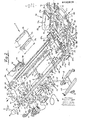
Im folgenden wird die Erfindung anhand zweier Ausführungsbeispiele, die in den Zeichnungen jeweils in auseinandergezogener Darstellung wiedergegeben sind, rein beispielsweise näher erläutert. Dabei zeigen:
- Fig. 1 die Bauteile eines Bausatzes nach der Erfindung für die Erstellung eines Geradförderers, und
- Fig. 2 in der Darstellung gemäß Fig. 1 entsprechender Darstellung einen Bausatz nach der Erfindung für die Erstellung eines Knickbandförderers.
- Fig. 1 shows the components of a kit according to the invention for the creation of a straight conveyor, and
- Fig. 2 in the representation according to Fig. 1 corresponding representation of a kit according to the invention for the creation of an articulated belt conveyor.
Wie dargestellt, ist für die Bildung des Förderbandrahmens ein Paar von Rahmenlängsholmen 2 aus C-Profilmaterial mit - ebenem Bodensteg 2a und zu diesem parallelen oder aber leicht auf diesen zu geneigten Randstegen 2b vorgesehen. Diese Rahmenlängsholme weisen auf der Mittellinie m ihres Bodensteges 2a eine Vielzahl in gleichem Abstand zueinander angeordneter Löcher 3 auf, die hier als Rundlöcher ausgebildet sind, aber auch als beispielsweise Langlöcher mit in der oder wenigstens quer zur Richtung der Rasterlinie m gleicher Größe ausgebildet sein könnten.As shown, for the formation of the conveyor belt frame, a pair of longitudinal frame spars 2 made of C-profile material with a flat base web 2a and parallel to it or slightly inclined to this edge webs 2b is provided. These longitudinal frame spars have on the center line m of their base web 2a a multiplicity of holes 3 arranged at the same distance from one another, which are formed here as round holes, but could also be formed, for example, as elongated holes with the same size in or at least transverse to the direction of the grid line m.
Zum Zusammenhalt beider Rahmenlängsholme 2 eines Paares derselben sind mehrere Verbindungselemente 4 vorgesehen, die hier als Abschnitte gleicher Länge von Rechteckrohrmaterial ausgebildet sind, an derer beiden Enden jeweils ein sich etwa achsnormal wegerstreckender Randflansch 33 vorgesehen ist, der jeweils zwei Löcher 6 etwa gleicher Größe wie der der Löcher 3 der Rahmenlängsholme 2 aufweist, die in einem dem Lochabstand zweier Löcher 3 der Rahmenlängsholme 2 entsprechenden Lochabstand zueinander angeordnet sind, der jedoch nicht notwendigerweise dem Lochabstand zweier benachbarter Löcher 3 der Rahmenlängsholme 2 zu entsprechen braucht, sondern auch einem Vielfachen desselben, wie im vorliegenden Fall dem Doppelten, entsprechen kann. Für die Verbindung der Querholme 4 mit den beidseitig anzuschließenden Rahmenlängsholmen 2 sind Verschraubungen 28 vorgesehen, die mit Vorzug aus Schraubbolzen, Mutter mit Unterlegscheibe und ggf. Kontermutter bestehen können.To hold together the two longitudinal beams 2 of a pair of The same several connecting elements 4 are provided, which are designed here as sections of the same length of rectangular tube material, at each end of which an
Der so gebildete Förderbandrahmen der als Ganzes mit 1 bezeichneten Bandfördervorrichtung wird von einem Paar von Standfüßen 9 getragen, die jeweils aus einem Paar von Standpfeilern 32 gebildet sind, welche durch zwei Querholme 45 miteinander verbunden sind, die ähnlich wie die Querholme 4 als Abschnitte von Rundrohr- oder Rechteck -- rohrmaterial ausgebildet sein können und an deren Stirnenden jeweils Anschlußflansche46 beispielsweise durch Schweißen festgelegt sind, die Löcher 46 aufweisen, welche mit entsprechenden Löchern in den Standpfeilern32 fluchten, so daß mittels Verschraubungen 85 ein biege- und torsionssteifer Standfuß 9 aus Standpfeilern 32 und Querholmen 45 gebildet werden kann. Dabei können die Standpfeiler 32 entweder einstückig ausgebildet sein, wie bei dem rechten Standfuß 9 dargestellt, oder aber aus mehreren Teilstücken 32a, 32b, 32c zusammengesetz sein, die teleskopisch ineinander einführbar sind, wie bei dem einen Standpfeiler des linken Standfußes 9 dargestellt. Die Standpfeiler können aus Rechteckrohr und/oder aus einem anderen Profilmaterial, wie beispielsweise einem C-Profil 32c, erstellt sein, wie dargestellt. Zur Verbindung einzelner Teilstücke eines Standpfeilers 32 können in dessen Inneres einführbare Laschen 86 vorgesehen sein, welche als Klemmplatten oder Widerlager für entsprechende zwar angedeutete, nicht jedoch näher dargestellte Verschraubungen dienen. Eine Ausführung mit aus mindestens zwei gegeneinander teleskopierbaren Teilen gebildeten Standpfeilern 32 wird immer dort vorzusehen sein, wo es gilt, ohne Austausch der Standfüße 9 gegen andere die Förderneigung der Bandfördervorrichtung 1 zu verändern. Die Standpfeiler 32 selbst weisen an ihren unteren Enden jeweils Fußplatten 43 auf.The conveyor belt frame thus formed of the belt conveyor device designated as a whole by 1 is supported by a pair of feet 9, each of which is formed from a pair of
Zur Anpassung an eine bei Veränderung der Förderneigung der Bandfördervorrichtung 1 notwendigerweise auftretende Änderung der relativen Winkelstellung von Förderbandrahmen und Standpfeilern 32 sind Schwenkflansche 47 vorgesehen, von denen jeweils einer einem Standpfeiler 32 zugeordnet ist und die längs ihres oberen Randes eine Anzahl von Löchern 48 etwa gleicher Größe wie der der Löcher 3 der Längsholme 2 aufweisen, welche in gleicher Rasteranordnung wie letztere vorgesehen sind, so daß die Schwenkflansche 47 über gleichfalls wiederum mit Vorzug aus Schraubbolzen, Mutter mit Unterlegscheibe und ggf. Kontermutter bestehende Verschraubungen 28 an beliebiger geeigneter Stelle der Rahmenlängsholme 2 festgelegt werden können. Die Schwenkflansche 47 weisen jeweils weiterhin ein Loch 49 und einen zu diesem konzentrischen kreisbogenförmigen Schlitz 50 auf, wobei der dem Krümmungsradius desselben entsprechende Abstand zum Mittelpunktsloch 49 dem Abstand zweier Flanschlöcher 13 in jeweils einem am oberen Ende eines jeden Standpfeilers 32 durch Verschraubung festlegbaren Anschlußflansch 11 entsprechen. Durch das Mittelpunktsloch 49 des Schwenkflansches 47 und das obere Loch 13 des Anschlußflansches 11 greift ein als Schwenklager dienender Schraubbolzen 51 hindurch, der mittels Mutter mit Unterlegscheibe und gegebenenfalls Kontermutter,erforderlichenfalls unter Zuhilfenahme einer Klemmplatte, festgelegt werden kann. Durch den kreisbogenförmigen Schlitz 50 des Schwenkflansches 47 und das untere Loch 13 des Anschlußflansches 11 greift eine Feststellverschraubung 52 hindurch, mittels derer der Schwenkflansch 47 und mitihm der Förderbandrahmen in jeder beliebigen Schwenkstellung, die der Länge des Kreisbogenschlitzes entspricht, festlegbar ist.In order to adapt to a change in the relative angular position of the conveyor belt frame and
An der rechts unten gezeigten Aufgabestelle für das Fördergut ist eine praktisch über der ganzen Breite des Förderbandrahmens durchgehende Aufgabewalze 20 mit einer Achse 21 vorgesehen, die unter Zwischenschaltung von zwar. dargestellten, nicht jedoch näher bezeichneten Distanzringen und Zwischenlegscheiben von einem Paar von Walzenträgern 15 abgestützt wird, von denen jeder auf seiner aufgabewalzenwellen- bzw. -achsenfernen Seite ein Endstück 17 aufweist, das so konturiert ist, daß es in den Profilhohlraum des zugeordneten Rahmenlängsholmprofils 2 einführbar ist. Die Wellenträger 15 weisen ferner jeweils eine Nase 16 mit einem zwar dargestellten, nicht jedoch näher bezeichneten Gewindeloch auf, in das ein Gewindestift 19 einer durch diesen und die Nase 16 mit ihrem Gewindeloch gebildeten Spanneinrichtung für die Aufgabewalzenachse 21 einschraubbar und mittels einer zwar dargestellten, nicht jedoch näher bezeichneten Kontermutter in einer beliebigen gewünschten Arbeits-Dabei stellung festlegbar ist kann sich der Gewindestift mit seinem freien Ende unmittelbar oder aber unter Zwischenschaltung eines gegenüber ihm frei drehbaren Druckstückes (nicht gezeigt) an der Aufgabewalzenachse 21 in Anlage befinden. Beim dargestellten Ausführungsbeispiel weist der Gewindestift 19 an seinem freien Ende einen fest an ihm angeordneten Aufnahmering für die Aufgabewalzenachse 21 auf, die sich in diesem drehen kann oder aber, sofern die gesamte Aufgabewalzenanordnung 20, 21 als Steckachsanordnung ausgebildet ist, mittels einer zwar dargestellten, nicht jedoch näher bezeichneten Madenschraube, die den Aufnahmering über eine Gewindebohrung in diesem durchdringt, an diesem drehfest festgelegt sein kann. Beim dargestellten Ausführungsbeispiel ist das Loch in der Nase 16 des Walzenträgers 15 nicht als Gewindeloch, sondern als Durchsteckloch für den Gewindestift 9 ausgebildet, der in dieses einfach eingesteckt wird. Der Achsabstand der Aufgabewalzenachse 21 zum Stirnende des zugeordneten Rahmenlängsholmprofils 2, an dem die Nase 16 des im Zusammenbauzustand in dessen Profilhohlraum mit seinem Endstück 17 eingeführten Walzenträgers 15 sich in Anlage befindet, wird durch Betätigung der zwar dargestellten, nicht jedoch näher bezeichneten Stellmutter des Gewindestiftes 19 in beliebiger gewünschter Arbeitsstellung eingestellt und fixiert. Zur Festlegung der Walzenträger 15 an den zugeordneten Rahmenlängsholmprofilen 2 weisen die Endstücke 17 der Walzenträger 15 jeweils einen im Zusammenbauzustand symmetrisch zur Rasterlinie m (Mittellinie des Bodensteges 2a der Rahmenlängsholmprofile 2 und vorzugsweise auch der Endstücke 17 der Walzenträger 15) angeordneten Sackschlitz 18 auf. Die Fixierung erfolgt dann mittels mindestens zweier durch Löcher 3 in den Rahmenlngsholmen 2 und den Sackschlitz 18 des in dessen Profilhohlraum eingeführten Walzenträgers 15 hindurchgreifender Verschraubungen 28 erforderlichenfalls unter Zuhilfenahme einer Klemmplatte 30, wobei auch hier diese Verschraubungen 28 mit Vorzug aus einem Schraubbolzen und Mutter mit Unterlegscheibe sowie gegebenenfalls einerKontermutter bestehen können. Wie dargestellt, kann dabei gleichzeitig auch ein Stützhorn 64 mitfestgelegt werden, das längs seines oberen Randes mindestens zwei Löcher 65 etwa gleicher Größe wie der der Löcher 3 der Rahmenlängsholme in der Rasteranordnung derselben entsprechender Anordnung aufweist. Andererseits kann ein solches Stützhorn, das im übrigen bevorzugt paarweise an beiden Rahmenlängsholmen 2 vorgesehen wird, auch an anderer Stelle und unabhängig von der Fixierung des Walzenträgers 15 am Rahmenlängsholm 2 festgelegt werden.At the feed point for the material to be conveyed shown at the bottom right, a
Am anderen Ende des Förderbandrahmens ist eine gleichfalls über praktisch dessen gesamter Breite durchgehende Abgabewalze 40 mit ihrer Welle 41 unter Zwischenschaltung von zwar dargestellten, nicht jedoch näher bezeichneten Lagern in'einem Paar von Abgabewalzenträgern 35 abgestützt, die jeweils auf ihrer abgabewalzenfernen Seite ein Endstück 37 aufweisen, mit welchem sie im Zusammenbauzuptand in den Profilhohlraum des zugeordneten Längsholms 2 eingeführt sind, gegenüber dessen Stirnseite sie sich mit einer Nase 36 abstützen. Da die Abgabewalze 40 beim dargestellten Ausführungsbeispiel als Antriebswalze für das sich in Förderrichtung F bewegende, über sie und die Aufgabewalze 20 gespannte Fördermittel in Form eines Bandes 27 ausgebildet ist, weisen die damit als Antriebswalzenträger dienenden Abgabewalzenträger 35 anders als die Aufgabewalzenträger 15 kein nach außen offenes Aufnahmemaul für die betreffende Welle bzw. Achse auf, sondern eine geschlossene Lageraufnahme, wie dargestellt. Andererseits sind die Endstücke 37 der Walzenträger 35 in der gleichen Weise mit einem Sackschlitz 38 ausgestattet, wie für die Endstücke 17 der Walzenträger 15 vorstehend beschrieben. Die Festlegung der Walzenträger 35 an den zugeordneten Längsholmprofilen 2 erfolgt in der gleichen Weise,wie im Zusammenhang mit den Aufgabewalzenträgern 15 bereits beschrieben, mittels Verschraubungen 28, erforderlichenfalls unter Zuhilfenahme einer Klemmplatte 30.At the other end of the conveyor belt frame, a
Zur Erzielung einer von der Stellung der Aufgabewalze 20, die durch die Spanneinrichtung 16, 19 bestimmt wird, wie vorstehend bereits beschrieben, und einer damit erzielten Spannwirkung für das Fördermittel 27 unabhängigen weiteren Spannmöglichkeit im Bereich der Antriebswalze 40 weist jeweils die Nase 36 von deren Wal-zenträger 35 eine Gewindebohrung auf, in welche ein Gewindestift 39 eingeschraubt wird, der sich mit seinem rahmenlängsholmseitigen Ende an einer entsprechenden Anschlagfläche am Rahmenlängsholm 2, wie etwa einem zusätzlich zum Endstück 37 des Walzenträgers 35 in dessen Profilhohlraum geschobenen Stützwinkel 94., abstützt und durch mehr oder weniger weites Einschrauben die Achsstellung der Abgabewalzenwelle 41 relativ zur Stirnfläche des zugeordneten Rahmenlängsholms 2 bestimmt.In order to achieve a further possibility of tensioning in the area of the
Am einen Rahmenlängsholm 2 ist ferner ein Lagerschild 24 für einen Antriebsmotor 22 festgelegt, und zwar dies mittels durch in der Rasteranordnung der Löcher 3 im Rahmenlängsholm 2 entsprechender Anordnung vorgesehene Löcher 26 etwa gleicher Größe wie der der Löcher 3 des Rahmenlängsholms 2 hindurchgreifender Verschraubungen 28, welche gleichfalls wiederum mit Vorzug aus Schraubbolzen, Mutter mit Unterlegscheibe und gegebenenfalls Kontermutter, erforderlichenfalls zusätzlich einer Klemmplatte 30, bestehen können. Am Lagerschild 24 ist mittels durch in der Anordnung des Bohrungsbildes des Standflansches 22a des Antriebsmotors 22 entsprechender Anordnung vorgesehene Motorbefestigungslöcher 25 hindurchgreifender Verschraubungen 29 der als Getriebemotor ausgebildete Antriebsmotor 22 festgelegt. Auf dessen Abtriebswelle ist, wie angedeutet, das zwar dargestellte, nicht jedoch näher bezeichnete Antriebsritzel eines als Kettentrieb ausgebildeten kinematischen Antriebskettenzuges 23 aufgekeilt, dessen Abtriebsritzel mit der als Antriebswelle fungierenden Welle 41 der Abgabewalze 40 drehfest verbunden ist. Durch diese Anordnung erhält ersichtlich die Spanneinrichtung 36, 39 für die Abgabewalze 40 gleichzeitig auch die Funktion einer Spanneinrichtung für den kinematischen Antriebskettenzug 23, mittels welcher dessen Kettenspannung auf das gewünschte Maß gebracht werden kann, obgleich natürlich nicht die gleichfalls vorhandene Funktion der Spanneinrichtung 36, 39 übersehen werden darf, die gesamte Bandfördervorrichtung 1 hinsichtlich ihrer Abgabestelle erforderlichenfalls abstandsmäßig an ein etwa vorhandenes nachfolgendes Förderaggregat anzupassen. Weiterhin sind auch noch die beiden Teilstücke 86 und 87 des den Kettentrieb 23 ab- deckenden Kettenkastens mit ihren zugehörigen Verschraubungen dargestellt, von denen die eine stirnseitig in ein nicht dargestelltes Sackloch des Walzenträgers 35 eingreifen kann.A bearing plate 24 for a
Dem Lagerschild 24 benachbart ist ein weiterer Lagerschild 80 für ein Steuerpult 79 für den Antriebsmotor 22 dargestellt, das mindestens zwei in der Rasteranordnung der Löcher 3 der Rahmenlängsholme 2 entsprechender Anordnung vorgesehene Löcher 81 etwa gleicher Größe wie der der Löcher 3 der Rahmenlängsholme 2 aufweist und über Ver- schraubungen 28, die wiederum mit Vorzug aus Schraubbolzen, Mutter mit Unterlegscheibe und Kontermutter bestehen können, am Rahmenlängsholm 2 festlegbar ist. Mittels durch weitere Löcher 82 hindurchgreifender Verschraubungen 83 ist an diesem Lagerschild 80 das Steuerpult 79 festgelegt.Adjacent to the end shield 24 is a further end shield 80 for a
Weiterhin sind in Fig. 1 die einen Lagerschilde zweier Paare von Lagerschilden 95 für Führungswalzen 97 für das Untertrum des Fördermittels 27 dargestellt, welche jeweils eine Aufnahmebohrung 98 für die Achse der zugeordneten Führungswalze 97 und längs ihres oberen Randes jeweils mindestens zwei in der Rasteranordnung der Löcher 3 der Rahmenlängsholme 2 entsprechender Anordnung vorgesehene Löcher 96 etwa gleicher Größe wie der der Löcher 3 der Rahmenlängsholme 2 aufweisen, über die sie mit den Rahmenlängsholmen 2 mittels wiederum mit Vorzug aus Schraubbolzen, Mutter mit Unterlegscheibe und gegebenenfalls Kontermutter bestehender Verschraubungen 28 (nicht dargestellt) an beliebiger für wünschenswert oder erforderlich erachteter Arbeitsstelle verbunden werden können.Furthermore, FIG. 1 shows the one end shields of two pairs of end shields 95 for
Weiterhin zeigt Fig. 1 auch noch einen Aufgabetrichter 71, der aus mehreren Teilstücken 71a, 71b zusammengesetzt sein kann und an der Aufgabestelle für das Fördergut oberhalb des Förderbandrahmens anzuordnen ist, indem die unteren Bereiche seiner den Rahmenlängsholmen 2 zugeordneten Teilstücke 71a (von denen nur eines gezeigt ist) jeweils in der Anordnung der Löcher 3 der Rahmenlängsholme 2 entsprechender Anordnung vorgesehene Löcher 74 aufweisen;über welche sie mittels Ver- schraubungen 28, die gleichfalls mit Vorzug aus Schraubbolzen, Mutter mit Unterlegscheibe und gegebenenfalls Kontermutter bestehen können, mit dem zugeordneten Rahmenlängsholm 2 in bereits beschriebener Weise verbunden werden können, so daß der gesamte Aufgabetrichter 71 von den beiden gegenüberliegenden Rahmenlängsholmen 2 getragen wird. Weiterhin kann das Stirnteil 71b des Aufnahmetrichters 71 ein Abdeckblech 72 für die Aufgabewalze 20 tragen, indem dieses mittels einer Klemmleiste 73 und zwar dargestellte, nicht jedoch näher bezeichnete Verschraubungen am Bauteil 71b festgelegt ist. Ein solcher Aufgabetrichter 71 wird für Schüttgut als Fördergut zu bevorzugen sein. Ist Stückgut als Fördergut zu handhaben, so wird sich meist ein Aufgabeschlürblech (nicht dargestellt) als seitliche Begrenzung der Aufgabestelle für das Fördergut empfehlen.Furthermore, Fig. 1 also shows a
Das Ausführungsbeispiel eines Bausatzes nach der Erfindung gemäß Fig. 1 sieht ferner Seitenbegrenzungsleisten 66 für das auf dem Obertrum des Fördermittels 27 geförderte Fördergut vor, von denen lediglich eine dargestellt ist. Sie ist, wie angedeutet, als Winkelprofil ausgebildet, und in ihrem nach unten weisenden Flansch sind Löcher 67 vorgesehen. Hat dieser nach unten weisende Flansch der Seitenbegrenzungsleiste 66 eine ausreichende Breite, so kann er für die Befestigung der Seitenbegrenzungsleiste 66 unmittelbar am zugeordneten Rahmenlängsholm 2 vorgesehen sein, indem die Löcher 67 in einer Vielzahl und in der Rasteranordnung der Löcher 3 im Rahmenlängsholm 2 entsprechender Anordnung sowie mit etwa gleicher Größe der Löcher 3 der Rahmenlängsholme 2 vorgesehen sind. Die Festlegung an den Rahmenlängsholmen 2 erfolgt dann in bereits beschriebener Weise mittels Verschraubungen 28. Liegt jedoch das Obertrum des Fördermittels 27 um ein solches Maß oberhalb der Rasterlinie m, daß die Breite des sich nach unten erstreckenden Flansches der Seitenbegrenzungsleiste 66 für eine unmittelbare Festlegung nicht ausreicht, so können die Löcher 67 in gleicher oder anderer Anordnung vorgesehen sein. In einem solchen Falle wird nämlich je Seitenbegrenzungsleiste 66 mindestens ein Paar von Tragflanschen 68 vorgesehen, von denen lediglich einer dargestellt ist. Diese weisen dann der Anordnung der Löcher 67 entsprechend angeordnete Löcher 69 auf, über die der Tragflansch 68 mit der Seitenbegrenzungsleiste 66 verbunden werden kann. Weiterhin weist aber jeder Tragflansch 68 auch noch mindestens zwei in der Rasteranordnung der Löcher 3 der Rahmenlängsholme entsprechender Anordnung vorgesehene Löcher 70 etwa gleicher Größe wie die Löcher 3 der Rahmenlängsholme 2 auf, über die der Tragflansch 68 in vorstehend bereits vielfach beschriebener Weise mittels Verschraubungen 28 (nicht dargestellt) am zugeordneten Rahmenlängsholm 2 so festgelegt werden kann, daß die Seitenbegrenzungsleiste 66 in richtiger Zuordnung zum Obertrum des Fördermittels 27 ihre Arbeitsstellung einnimmt.The exemplary embodiment of a kit according to the invention according to FIG. 1 further provides side limitation strips 66 for the conveyed goods conveyed on the upper run of the conveying
Für manche Fördereinsätze ist es erwünscht, wenn das Obertrum des Fördermittels 27 über seiner gesamten Arbeitslänge kontinuierlich von seiner Unterseite her unterstützt wird. Hierfür kann ein Stützblech 88 vorgesehen sein, das vom Förderbandrahmen getragen wird, indem es längs seiner beiden Randkanten jeweils auf einer Tragleiste 90 ruht, die unter Zwischenschaltung einer ausreichendes Laufspiel für das Obertrum des Fördermittels 27 gewährleistenden Distanzleiste 89 mittels Verschraubungen 91 von unten her an dem oberen Seitensteg des Rahmenlängsholmprofils 2 und/oder mit Vorzug dem zu diesem parallelliegenden Mittelbereich des Profils der Seitenbegrenzungsleiste 66 verschraubt wird.For some conveying applications, it is desirable if the upper run of the conveying
Das Ausführungsbeispiel gemäß Fig. 2 ist im wesentlichen in der gleichen Weise ausgeführt wie das gemäß Fig. 1, so daß auf die vorstehende Beschreibung des letzteren Bezug genommen werden kann und lediglich hiervon abweichende Einzelheiten des Ausführungsbeispiels gemäß Fig. 2 im folgenden näher erläutert werden.The embodiment according to FIG. 2 is carried out essentially in the same way as that according to FIG. 1, so that reference can be made to the above description of the latter and only details of the embodiment according to FIG. 2 which differ from this are explained in more detail below.
Erst einmal ist darauf hinzuweisen, daß alternativ oder zusätzlich zu den Querholmen 4 bereits beschriebener Ausbildung mindestens ein Verbindungselement 5 in Form einer U-förmigen Rinne mit von ihrem Mittelsteg 5a sich gleichsinnig etwa normal wegerstreckenden Randstegen 5b vorgesehen sein kann, dessen Gesamtbreite so gewählt ist, daß sie gerade dem Abstandsmaß der Innenflächen oder der Außenflächen der sich im Zusammenbauzustand gegenüberliegenden Rahmenlängsholme 2 entspricht. In den Randstegen 5b sind jeweils mindestens zwei Löcher 7 etwa gleicher Größe wie der der Löcher 3 der Rahmenlängsholme 2 mit deren Rasteranordnung entsprechender Anordnung vorgesehen, so daß mittels Verschraubungen 28 in vorstehend bereits vielfach beschriebener Weise das jeweilige Verbindungselement 5 in den Verbund des Förderbandrahmens eingefügt werden kann. Die Länge 1 des U-rinnenförmigen Verbindungselementes 5 kann dabei etwa der Länge der Rahmenlängsholme 2 entsprechen. In einem solchen Falle werden die Querholme 4 entbehrlich, zumal durch ein solches Verbindungselement 5 dem Förder- bandrahmen eine erheblich größere Biege- und/oder Torsionssteifigkeit vermittelt wird. Entbehrlich werden die Querholme 4 aber auch bei Verwendung von Verbindungselementen 5 besehriebener.Art mit geringerer Länge 1. Neben der Ausnutzung seiner Aussteifungsfunktion kann ein U-rinnenförmiges Verbindungselement 5 aber auch noch so eingesetzt werden, daß es zur Erfüllung von Unfallverhütungsvorschriften gleichzeitig auch noch als Eingreifschutz für den aufgabe- bzw. abgabewalzenseitigen Bereich des Untertrums des Fördermittels 27 dient. Wird die Länge 1 solcher Verbindungselemente 5 geringer als die Hälfte der Länge der Rahmenlängsholme 2 bzw. höchstens entsprechend derselben gewählt, so lassen sich die Verbindungselemente 5 zweckmäßig auch als die Stöße zwischen zwei aufeinanderfolgenden Paaren von Rahmenlängsholmen 2 überbrückende Verbindungslaschen einsetzen.First of all, it should be pointed out that, as an alternative or in addition to the crossbars 4 already described, at least one connecting element 5 in the form a U-shaped channel with edge webs 5b extending in the same direction from its central web 5a, the overall width of which is selected such that it corresponds exactly to the distance between the inner surfaces or the outer surfaces of the longitudinal frame spars 2 which are opposite in the assembled state. In the edge webs 5b at least two holes 7 of approximately the same size as that of the holes 3 of the longitudinal beams 2 with their grid arrangement corresponding arrangement are provided so that the respective connecting element 5 can be inserted into the assembly of the conveyor belt frame by means of
Statt der beiden Standfüße 9 gemäß Fig. 1 ist hier ein einziger die gesamte Bandfördervorrichtung 1 tragender Standfuß 8 vorgesehen. Dieser weist einen einzigen mittigen Standpfeiler 31 auf, der mit seinem unteren Ende teleskopisch geführt und über eine zwar dargestellte, nicht jedoch näher bezeichnete Feststelleinrichtung in einem verfahrbaren Standschemel 42 höhenverstellbar geführt ist und an seinem schemelfernen Ende Querholm 44 trägt, an dessen beiden Stirnenden jeweils beispielsweise mittels Schweißens ein Anschlußflansch 10 festgelegt ist, wobei beide Anschlußflansche einen solchen Abstand zueinander haben, der dem Abstandsmaß zwischen den Innenflächen oder zwischen den Außenflächen zweier im Zusammenbauzustand gegenüberliegender Rahmenlängsholme 2 entspricht. Diese weisen jeweils übereinander angeordnet zwei Flanschlöcher 12 auf. Kommt es auf eine Veränderung der Förderneigung der Bandfördervorrichtung 1 nicht an, so können die Löcher 12 in den Anschlußflanschen 10 auch in der Rasteranordnung der Löcher 3 der Rahmenlängsholme 2 entsprechender Anordnung und mit etwa gleicher Größe ausgeführt sein, so daß der Standfuß über die Anschlußflansche 10 des Querholms 44 seines Standpfeilers 31 unmittelbar an den Rahmenlängsholmen 2 angeschlossen werden kann. Ist hingegen eine Verstellbarkeit der Förderneigung erwünscht, so werden die Flanschlöcher 12 in dargestellter Anordnung mit gleichem Abstand wie dem des kreisbogenförmigen Schlitzes zu seinem Mittelpunktsloch 49 im dargestellten Schwenkflansch 47 ausgeführt, und der Anschluß des Standfußes 8 erfolgt über die Anschlußflansche 10 in der gleichen Weise, wie bereits im Zusammenhang mit Fig. 2 bezüglich des Anschlusses der Anschlußflansche 11 der Standfüße 9 beschrieben.Instead of the two feet 9 according to FIG. 1 there is one only the
Da es sich bei der Ausführungsform der Erfindung gemäß Fig. 2 um einen Knickbandförderer handelt, weist dieser zwei Paare von Rahmenlängsholmen 2 auf, die im Bereich der Knickstelle über eine als Ganzes mit 53 bezeichnete Umlenkeinrichtung mit paarweise vorgesehenen Lagerträgern 54 verbunden sind, die jeweils zwei Schenkel 55a, 55b aufweisen und mittels einer jeweils durch miteinander fluchtende Löcher in diesen gemeinsam hindurchgreifender Verschraubungen 84 in ihrer winkelmäßigen Zuordnung zueinander veränderbar und in der gewünschten Winkelstellung zueinander festgelegt haltbar sind. Beide Schenkel 55a, 55b eines jeden Lagerträgers 54 weisen jeweils ein in den Profilhohlraum des benachbarten Rahmenlängsholmes 2 einführbares Endstück 57a bzw. 57b mit jeweils einem sichsymmetrisch zur Rasterlinie m des zugeordneten Rahmenlängsholms 2 erstreckenden Sackschlitz 58a bzw. 58b auf, das in bereits im Zusammenhang mit den Walzenträgern der Aufgabewalze 20 bzw. der Abgabewalze 40 gemäß Fig. 1 beschriebener Weise mittels Verschraubungen 28 erforderlichenfalls. unter Zuhilfenahme von Klemmplatten 30 am jeweils zugeordneten Rahmenlängsholm 2 fixiert werden kann. Die Halterung der Aufgabewalze 20 am freien Ende des rechts unten dargestellten Rahmenlängsholmpaares ist im übrigen die gleiche, wie bereits im Zusammenhang mit Fig. 1 beschrieben.Since the embodiment of the invention according to FIG. 2 is an articulated belt conveyor, it has two pairs of longitudinal frame bars 2, which are in the area the kink are connected via a deflection device, designated as a whole as 53, to bearing supports 54 provided in pairs, each of which has two
Die aufgabe walzenseitigen Schenkel 55b weisen jeweils eine Lagerung für Niederhalterollen 62 für das Obertrum des Fördermittels 27 in Form von durch Schraubbolzen 63 gebildeten Achsen auf, die mit einem sich nach oben erstreckenden Lappen dieses Schenkels 55b verschraubt werden. Die anderen Schenkel 55a lagern in der gleichen Weise, wie die Aufgabewalze 20 in ihren Walzenträgern 15 gelagert ist, die Achse 61 einer Umlenkwalze 60 für das Untertrum des Fördermittels 27.In diesem Zusammenhang ist hervorzuheben, daß auch die Funktionsweise der durch eine Nase 56a am Schenkel 55a und das Schraubstück 59a gebildeten Spanneinrichtung der Umlenkeinrichtung 53 für die Umlenkwalze 60 die gleiche ist wie die der Spanneinrichtung 16, 19 für die Aufgabewalze 20.The task roller-side legs 55b each have a mounting for hold-down rollers 62 for the upper run of the conveying means 27 in the form of axes formed by screw bolts 63, which are screwed together with an upwardly extending tab of this leg 55b. The
Auch hinsichtlich des Aufgabetrichters 71 ist der erfindungsgemäße Bausatz gemäß Fig. 2 im wesentlichen in der gleichen Weise ausgebildet wie der gemäß Fig. 1, wenn auch die Einzelteile 71a, 71b für diesen eine andere Ausführung aufweisen. Hier ist der Aufgabetrichter 71 statt für seitliche Verschraubung an und mit den Rahmenlängsholmen 2, wie vorstehend im Zusammenhang mit Fig. 1 beschrieben, für Aufsetzen auf die oberen Seitenstege des Profils der Rahmenlängsholme 2 vorgesehen, auf denen er mittels Verschraubungen 99 fixiert werden kann. Der sich vom unteren Ende der seitlichen Teilstücke 71a seitlich wegerstreckende Standflansch derselben dient ferner dazu, mittels einer nicht dargestellten Tragleiste über eine Distanzleiste 93 ein das Obertrum des Fördermittels 27 im Bereich der Aufgabestelle für das Fördergut von seiner Unterseite her abstützendes Gleitblech 92 zu tragen. Auf der Länge des ansteigenden Astes des Bandförderers 1 ist in der gleichen Weise wie vorstehend im Zusammenhang mit der Ausführungsform gemäß Fig. 1 beschrieben, ein Gleitblech 88 das Obertrum des Fördermittels 27 untergreifend gehalten, das jedoch in Fig. 2 nicht dargestellt ist.With regard to the
Im Bereich der Abgabestelle des Fördergutes ist ein Paar von Abgabeschlürwänden 74 angeordnet, von denen lediglich eine in Fig. 2 dargestellt ist. Sie ist als runenförmig abgekröpfter Blechformling ausgebildet und besitzt in seinem nach unten weisenden Flansch eine Anzahl in der Rasteranordnung der Löcher 3 der Rahmenlängsholme 2 entsprechender Anordnung vorgesehener Löcher 75 etwa gleicher Größe wie die Löcher 3 der Rahmenlängsholme 2. Ist der sich nach unten erstreckende Flansch der Abgabeschlürwand 74 mit genügender Breite ausgeführt, so kann in bereits vielfach beschriebener Weise mittels Verschraubungen 28 die Schlürwand 77 unmittelbar an den zugeordneten Rahmenlängsholmen 2 festgelegt werden. Bei im Hinblick auf die Laufhöhe des Obertrums des Fördermittels 27 ungenügender Breite des sich nach unten erstreckenden Flansches der Schlürwand 74 jedoch kann auch hier für jede Schlürwand 74 mindestens ein Tragflansch 76, vorzugsweise jedoch jeweils ein Paar solcher Tragflansche 76, vorgesehen sein, die längs ihrem oberen 'Rand jeweils mindestens 2 Löcher 77 aufweisen, mit denen sie über geeignete Verschraubungen mit dem sich nach unten erstreckenden Flansch der Schlürwand 74 verbunden werden können. Etwa längs ihres unteren Randes weisen die Tragflansche 76 ihrerseits nun jeweils mindestens 2 in der Rasteranordnung der Löcher 3 der Rahmenlängsholme 2 entsprechender Anordnung vorgesehene Löcher 78 etwa gleicher Größe wie die Löcher 3 der Rahmenlängsholme 2 auf, über welche sie und damit auch die jeweils zugeordnete Schlürwand 74 in beschriebener Weise mittels durch sie und entsprechend fluchtende Löcher 3 der Rahmenlängsholme 2 hindurchgreifender Verschraubungen 28 an diesen festgelegt werden können.In the area of the delivery point of the material to be conveyed, a pair of
Abschließend ist noch hervorzuheben, daß die Rahmenlängsholme 2 statt wie bei den in Fig. 1 und 2 dargestellten Ausführungsbeispielen der Erfindung als C-Profile auch als U-Profile ausgebildet sein können. Außerdem brauchen die Rahmenlängsholmprofile 2 sich nicht über die gesamte Länge der Bandfördervorrichtung 1 nach der Erfindung zu erstrecken, vielmehr kann deren Förderbandrahmen auch aus einer Vielzahl von Paaren von Rahmenlängsholmprofilen 2 zusammengesetzt sein, die dann entweder über in deren Profilhohlraum die Stoßstelle zwischen zwei solcher Paare von Rahmenlängsholmen 2 überbrückend eingreifende Verbindungslaschen, als welche im übrigen auch die Anschlußflansche 33 eines Querholms 4 dienen können, miteinander verbunden werden können, oder aber mit Vorzug durch ein in bereits beschriebener Weise als eine solche Stoßstelle zweier Paare von Rahmenlängsholmen 2 überbrückend eingesetztes U-rinnenförmiges Verbindungselement 5.Finally, it should be emphasized that the longitudinal frame spars 2 can also be designed as U-profiles instead of the C-profiles as in the exemplary embodiments of the invention shown in FIGS. 1 and 2. In addition, the longitudinal frame profiles 2 do not need to extend over the entire length of the
Im übrigen ist selbstverständlich, daß der Bausatz nach der Erfindung auch in den Ansprüchen nicht ausdrücklich hervorgehobene Verschraubungen, Verstiftungen, Distanzscheiben, Unterlegscheiben und dergleichen Maschinenelemente aufweisen kann, die jedoch für die Erfindung nicht wesentlich zu sein brauchen.Moreover, it goes without saying that the kit according to the invention can also have screw connections, pinnings, spacers, washers and similar machine elements which are not expressly emphasized in the claims, but which need not be essential for the invention.
Claims (35)
Priority Applications (1)
| Application Number | Priority Date | Filing Date | Title |
|---|---|---|---|
| AT84103920T ATE35665T1 (en) | 1983-04-12 | 1984-04-08 | KIT FOR THE CREATION OF BELT CONVEYOR DEVICES. |
Applications Claiming Priority (2)
| Application Number | Priority Date | Filing Date | Title |
|---|---|---|---|
| DE19838310729U DE8310729U1 (en) | 1983-04-12 | 1983-04-12 | KIT FOR THE CONSTRUCTION OF BELT CONVEYORS |
| DE8310729U | 1983-04-12 |
Publications (3)
| Publication Number | Publication Date |
|---|---|
| EP0122573A2 true EP0122573A2 (en) | 1984-10-24 |
| EP0122573A3 EP0122573A3 (en) | 1986-02-19 |
| EP0122573B1 EP0122573B1 (en) | 1988-07-13 |
Family
ID=6752211
Family Applications (1)
| Application Number | Title | Priority Date | Filing Date |
|---|---|---|---|
| EP84103920A Expired EP0122573B1 (en) | 1983-04-12 | 1984-04-08 | Kit for the construction of belt conveyor arrangements |
Country Status (3)
| Country | Link |
|---|---|
| EP (1) | EP0122573B1 (en) |
| AT (1) | ATE35665T1 (en) |
| DE (2) | DE8310729U1 (en) |
Cited By (17)
| Publication number | Priority date | Publication date | Assignee | Title |
|---|---|---|---|---|
| US4715488A (en) * | 1986-01-24 | 1987-12-29 | Hewitt Timothy W | Collapsible conveyor |
| EP0381941A1 (en) * | 1989-02-10 | 1990-08-16 | Geppert, Helmut, Dipl.-Ing. | Support for a belt conveyor |
| FR2654711A1 (en) * | 1989-11-17 | 1991-05-24 | Mannesmann Ag | DEVICE FOR MOUNTING A RETURN ROLL. |
| EP0536797A1 (en) * | 1991-10-10 | 1993-04-14 | Maschinenbau Heinrich Hajek GmbH & Co | Conveyor device for transporting products under moisture room conditions |
| US5205400A (en) * | 1991-10-11 | 1993-04-27 | Natec, Reich, Summer Gmbh & Co. Kg. | Transportation device for transportation of foodstuffs |
| WO2000071443A1 (en) * | 1999-05-21 | 2000-11-30 | Wittenstein Gmbh & Co. Kg | Fixing device for a part that can be inserted between two adjacent supports |
| EP1559668A1 (en) * | 2004-01-30 | 2005-08-03 | Caljan Rite-Hite ApS | Telescopic belt conveyor |
| FR2882737A1 (en) * | 2005-03-07 | 2006-09-08 | Sidel Sas | Conveyor device for transporting bottle case, has basic modules whose central structures are presented under form of closed box, and slat band chain type belt with upper and lower strands |
| FR2882738A1 (en) * | 2005-03-07 | 2006-09-08 | Sidel Sas | CONVEYOR DEVICE WITH A CARPET OF THE TYPE OF A CHAIN OF ENDLESS CHAIN WITH PALLETS FOR TRANSPORTING BOTTLE CASES. |
| EP1935782A1 (en) * | 2006-12-21 | 2008-06-25 | Telair International GmbH | Mounting layer for mounting loading devices on the loading deck of an aircraft |
| DE102007017628A1 (en) * | 2007-04-12 | 2008-10-23 | Maytec Aluminium Systemtechnik Gmbh | Conveyor, particularly for assembly-line, has bearing houses, where one or both bearing houses are supported and is articulated at associated side protection around vertical pendulum axle, shifted transverse to opposite side |
| FR2935964A1 (en) * | 2008-09-16 | 2010-03-19 | Ate Soc Nouvelle | Adjustable foot for belt lift to ascend product e.g. fruit to edge of storage bin, has roller mounted on case and arranged at free end of frame that is hinged on case using operating axle integrated with operating unit |
| ITMC20090239A1 (en) * | 2009-11-23 | 2011-05-24 | Daniele Serafini | CONVEYOR BELT. |
| EP2143670A3 (en) * | 2008-07-08 | 2012-03-28 | Ligmatech Automationssysteme GmbH | Modular belt conveyor |
| ITRM20110255A1 (en) * | 2011-05-24 | 2012-11-25 | Fabrizio Pagliarella | KIT FOR ASSEMBLY OF A CONVEYOR. |
| CN106005899A (en) * | 2015-03-30 | 2016-10-12 | 乔伊·姆·特拉华公司 | Take-up mechanism for conveyor system |
| CN111731772A (en) * | 2020-08-10 | 2020-10-02 | 罗博特科智能科技股份有限公司 | Transmission device with adjustable size |
Families Citing this family (3)
| Publication number | Priority date | Publication date | Assignee | Title |
|---|---|---|---|---|
| DE3409160A1 (en) * | 1984-03-13 | 1985-09-26 | Helmut 5162 Niederzier Geppert | FRAME FOR CONVEYOR DEVICES |
| DE102013215751A1 (en) * | 2013-08-09 | 2015-02-12 | Robert Bosch Gmbh | Deflection device for a conveyor chain with separate chain guide |
| CN104590848A (en) * | 2014-12-29 | 2015-05-06 | 山东东山王楼煤矿有限公司 | Loading and unloading support for electric roller belt conveyor |
Citations (5)
| Publication number | Priority date | Publication date | Assignee | Title |
|---|---|---|---|---|
| FR1332939A (en) * | 1962-08-31 | 1963-07-19 | Beco | Self-propelled elevator transporter |
| US3944054A (en) * | 1974-12-30 | 1976-03-16 | Power Pack Conveyor Company | Modular conveyor |
| FR2387873A1 (en) * | 1977-04-19 | 1978-11-17 | Masyc Ag | SET OF CONSTRUCTION ELEMENTS FOR MANUFACTURING ADAPTABLE SUPPORT FRAMES, ESPECIALLY FOR CONVEYOR DEVICES |
| US4172677A (en) * | 1974-08-27 | 1979-10-30 | Masyc Ag | Variable load-bearing framework |
| EP0074648A2 (en) * | 1981-09-11 | 1983-03-23 | Geppert, Helmut, Dipl.-Ing. | Frame for belt conveyor devices |
-
1983
- 1983-04-12 DE DE19838310729U patent/DE8310729U1/en not_active Expired
-
1984
- 1984-04-08 EP EP84103920A patent/EP0122573B1/en not_active Expired
- 1984-04-08 AT AT84103920T patent/ATE35665T1/en not_active IP Right Cessation
- 1984-04-08 DE DE8484103920T patent/DE3472657D1/en not_active Expired
Patent Citations (5)
| Publication number | Priority date | Publication date | Assignee | Title |
|---|---|---|---|---|
| FR1332939A (en) * | 1962-08-31 | 1963-07-19 | Beco | Self-propelled elevator transporter |
| US4172677A (en) * | 1974-08-27 | 1979-10-30 | Masyc Ag | Variable load-bearing framework |
| US3944054A (en) * | 1974-12-30 | 1976-03-16 | Power Pack Conveyor Company | Modular conveyor |
| FR2387873A1 (en) * | 1977-04-19 | 1978-11-17 | Masyc Ag | SET OF CONSTRUCTION ELEMENTS FOR MANUFACTURING ADAPTABLE SUPPORT FRAMES, ESPECIALLY FOR CONVEYOR DEVICES |
| EP0074648A2 (en) * | 1981-09-11 | 1983-03-23 | Geppert, Helmut, Dipl.-Ing. | Frame for belt conveyor devices |
Cited By (30)
| Publication number | Priority date | Publication date | Assignee | Title |
|---|---|---|---|---|
| US4715488A (en) * | 1986-01-24 | 1987-12-29 | Hewitt Timothy W | Collapsible conveyor |
| EP0381941A1 (en) * | 1989-02-10 | 1990-08-16 | Geppert, Helmut, Dipl.-Ing. | Support for a belt conveyor |
| FR2654711A1 (en) * | 1989-11-17 | 1991-05-24 | Mannesmann Ag | DEVICE FOR MOUNTING A RETURN ROLL. |
| EP0536797A1 (en) * | 1991-10-10 | 1993-04-14 | Maschinenbau Heinrich Hajek GmbH & Co | Conveyor device for transporting products under moisture room conditions |
| US5205400A (en) * | 1991-10-11 | 1993-04-27 | Natec, Reich, Summer Gmbh & Co. Kg. | Transportation device for transportation of foodstuffs |
| WO2000071443A1 (en) * | 1999-05-21 | 2000-11-30 | Wittenstein Gmbh & Co. Kg | Fixing device for a part that can be inserted between two adjacent supports |
| US6460688B1 (en) | 1999-05-21 | 2002-10-08 | Wittenstein Gmbh & Co. Kg | Fixing device for a part that can be inserted between two adjacent supports |
| US7168555B2 (en) | 2004-01-30 | 2007-01-30 | Rite-Hite Holding Corporation | Extendable conveyor |
| EP1559668A1 (en) * | 2004-01-30 | 2005-08-03 | Caljan Rite-Hite ApS | Telescopic belt conveyor |
| FR2882737A1 (en) * | 2005-03-07 | 2006-09-08 | Sidel Sas | Conveyor device for transporting bottle case, has basic modules whose central structures are presented under form of closed box, and slat band chain type belt with upper and lower strands |
| WO2006095078A1 (en) * | 2005-03-07 | 2006-09-14 | Sidel Participations | Endless slat-band-chain-type belt conveyor device for the transport of bottle crates |
| FR2882738A1 (en) * | 2005-03-07 | 2006-09-08 | Sidel Sas | CONVEYOR DEVICE WITH A CARPET OF THE TYPE OF A CHAIN OF ENDLESS CHAIN WITH PALLETS FOR TRANSPORTING BOTTLE CASES. |
| EP1935782A1 (en) * | 2006-12-21 | 2008-06-25 | Telair International GmbH | Mounting layer for mounting loading devices on the loading deck of an aircraft |
| US8286913B2 (en) | 2006-12-21 | 2012-10-16 | Telair International Gmbh | Fixing rail for attaching loading devices to the loading deck of an aircraft |
| DE102007017628A1 (en) * | 2007-04-12 | 2008-10-23 | Maytec Aluminium Systemtechnik Gmbh | Conveyor, particularly for assembly-line, has bearing houses, where one or both bearing houses are supported and is articulated at associated side protection around vertical pendulum axle, shifted transverse to opposite side |
| DE102007017628B4 (en) * | 2007-04-12 | 2012-04-05 | Maytec Aluminium Systemtechnik Gmbh | Conveyor belt with at least one deflectable roller mounted |
| EP2143670A3 (en) * | 2008-07-08 | 2012-03-28 | Ligmatech Automationssysteme GmbH | Modular belt conveyor |
| FR2935964A1 (en) * | 2008-09-16 | 2010-03-19 | Ate Soc Nouvelle | Adjustable foot for belt lift to ascend product e.g. fruit to edge of storage bin, has roller mounted on case and arranged at free end of frame that is hinged on case using operating axle integrated with operating unit |
| ITMC20090239A1 (en) * | 2009-11-23 | 2011-05-24 | Daniele Serafini | CONVEYOR BELT. |
| ITRM20110255A1 (en) * | 2011-05-24 | 2012-11-25 | Fabrizio Pagliarella | KIT FOR ASSEMBLY OF A CONVEYOR. |
| CN106005899A (en) * | 2015-03-30 | 2016-10-12 | 乔伊·姆·特拉华公司 | Take-up mechanism for conveyor system |
| GB2541048A (en) * | 2015-03-30 | 2017-02-08 | Joy Mm Delaware Inc | Take-up mechanism for conveyor system |
| US9624771B2 (en) | 2015-03-30 | 2017-04-18 | Joy Mm Delaware, Inc. | Take-up mechanism for conveyor system |
| US9850073B2 (en) | 2015-03-30 | 2017-12-26 | Joy Mm Delaware, Inc. | Take-up mechanism for conveyor system |
| US10138069B2 (en) | 2015-03-30 | 2018-11-27 | Joy Global Underground Mining Llc | Take-up mechanism for conveyor system |
| CN106005899B (en) * | 2015-03-30 | 2019-11-08 | 久益环球地下采矿有限责任公司 | The accommodating mechanism of transportation system |
| CN110641924A (en) * | 2015-03-30 | 2020-01-03 | 久益环球地下采矿有限责任公司 | Storage mechanism of conveying system |
| AU2016201957B2 (en) * | 2015-03-30 | 2021-01-21 | Continental Global Material Handling Llc | Take-up mechanism for conveyor system |
| GB2541048B (en) * | 2015-03-30 | 2021-04-07 | Joy Global Conveyors Inc | Take-up mechanism for conveyor system |
| CN111731772A (en) * | 2020-08-10 | 2020-10-02 | 罗博特科智能科技股份有限公司 | Transmission device with adjustable size |
Also Published As
| Publication number | Publication date |
|---|---|
| EP0122573B1 (en) | 1988-07-13 |
| EP0122573A3 (en) | 1986-02-19 |
| ATE35665T1 (en) | 1988-07-15 |
| DE3472657D1 (en) | 1988-08-18 |
| DE8310729U1 (en) | 1984-01-05 |
Similar Documents
| Publication | Publication Date | Title |
|---|---|---|
| EP0122573B1 (en) | Kit for the construction of belt conveyor arrangements | |
| WO2016026550A1 (en) | Conveyor device for transportation structures | |
| EP0457286A1 (en) | Sliding door | |
| EP2314529B1 (en) | Transport unit with accumulation roll chain | |
| EP0127748B1 (en) | Tensioning device for a conveyor belt | |
| EP0123785B1 (en) | Belt conveyor | |
| EP3837192B1 (en) | Transport device | |
| EP1714917B1 (en) | Roller conveyor | |
| DE3409160C2 (en) | ||
| EP0121920B1 (en) | Belt conveyor arrangement | |
| EP0156207B1 (en) | Safety device around the tail pulleys of a belt conveyor | |
| EP0112464B1 (en) | Tensioning device for scraper flight conveyors or similar conveyors or agricultural vehicles and machines | |
| DE4413008A1 (en) | Folding device for sheet layers | |
| EP0281887B1 (en) | Transporting device for paper products, in particular overlapped products | |
| DE3313190A1 (en) | Construction kit for producing belt conveying devices | |
| DE3313196C1 (en) | Device for tensioning a belt-shaped conveying element | |
| DE3313108C2 (en) | ||
| DE3718810A1 (en) | DEVICE FOR SECURING FILLER INPUT OR OUTLET OPENING OPENINGS IN BELT CONVEYORS | |
| EP0074648B1 (en) | Frame for belt conveyor devices | |
| DE3318174C2 (en) | ||
| DE3313141A1 (en) | Band-conveying apparatus | |
| DE3348204C2 (en) | Frame for belt conveyor apparatuses | |
| EP0284992B1 (en) | Snap-in rail | |
| DE3347796C2 (en) | ||
| DE1153721B (en) | Filing system with document containers running around like a paternoster |
Legal Events
| Date | Code | Title | Description |
|---|---|---|---|
| PUAI | Public reference made under article 153(3) epc to a published international application that has entered the european phase |
Free format text: ORIGINAL CODE: 0009012 |
|
| AK | Designated contracting states |
Designated state(s): AT BE CH DE FR GB IT LI LU NL SE |
|
| EL | Fr: translation of claims filed | ||
| TCNL | Nl: translation of patent claims filed | ||
| PUAL | Search report despatched |
Free format text: ORIGINAL CODE: 0009013 |
|
| AK | Designated contracting states |
Designated state(s): AT BE CH DE FR GB IT LI LU NL SE |
|
| 17P | Request for examination filed |
Effective date: 19860428 |
|
| 17Q | First examination report despatched |
Effective date: 19861001 |
|
| 18D | Application deemed to be withdrawn |
Effective date: 19870212 |
|
| 18RA | Request filed for re-establishment of rights before grant |
Effective date: 19870629 |
|
| D18D | Application deemed to be withdrawn (deleted) | ||
| GRAA | (expected) grant |
Free format text: ORIGINAL CODE: 0009210 |
|
| AK | Designated contracting states |
Kind code of ref document: B1 Designated state(s): AT BE CH DE FR GB IT LI LU NL SE |
|
| REF | Corresponds to: |
Ref document number: 35665 Country of ref document: AT Date of ref document: 19880715 Kind code of ref document: T |
|
| ITF | It: translation for a ep patent filed |
Owner name: DR. ING. AUSSERER ANTON |
|
| REF | Corresponds to: |
Ref document number: 3472657 Country of ref document: DE Date of ref document: 19880818 |
|
| ET | Fr: translation filed | ||
| GBT | Gb: translation of ep patent filed (gb section 77(6)(a)/1977) | ||
| PLBE | No opposition filed within time limit |
Free format text: ORIGINAL CODE: 0009261 |
|
| STAA | Information on the status of an ep patent application or granted ep patent |
Free format text: STATUS: NO OPPOSITION FILED WITHIN TIME LIMIT |
|
| 26N | No opposition filed | ||
| ITTA | It: last paid annual fee | ||
| PGFP | Annual fee paid to national office [announced via postgrant information from national office to epo] |
Ref country code: CH Payment date: 19920319 Year of fee payment: 9 |
|
| PGFP | Annual fee paid to national office [announced via postgrant information from national office to epo] |
Ref country code: LU Payment date: 19920325 Year of fee payment: 9 |
|
| PGFP | Annual fee paid to national office [announced via postgrant information from national office to epo] |
Ref country code: GB Payment date: 19920406 Year of fee payment: 9 |
|
| PGFP | Annual fee paid to national office [announced via postgrant information from national office to epo] |
Ref country code: SE Payment date: 19920416 Year of fee payment: 9 Ref country code: BE Payment date: 19920416 Year of fee payment: 9 |
|
| PGFP | Annual fee paid to national office [announced via postgrant information from national office to epo] |
Ref country code: FR Payment date: 19920424 Year of fee payment: 9 |
|
| PGFP | Annual fee paid to national office [announced via postgrant information from national office to epo] |
Ref country code: NL Payment date: 19920430 Year of fee payment: 9 Ref country code: AT Payment date: 19920430 Year of fee payment: 9 |
|
| EPTA | Lu: last paid annual fee | ||
| PG25 | Lapsed in a contracting state [announced via postgrant information from national office to epo] |
Ref country code: LU Free format text: LAPSE BECAUSE OF NON-PAYMENT OF DUE FEES Effective date: 19930408 Ref country code: GB Effective date: 19930408 Ref country code: AT Effective date: 19930408 |
|
| PG25 | Lapsed in a contracting state [announced via postgrant information from national office to epo] |
Ref country code: SE Effective date: 19930409 |
|
| PG25 | Lapsed in a contracting state [announced via postgrant information from national office to epo] |
Ref country code: LI Effective date: 19930430 Ref country code: CH Effective date: 19930430 Ref country code: BE Effective date: 19930430 |
|
| BERE | Be: lapsed |
Owner name: GEPPERT HELMUT Effective date: 19930430 |
|
| PG25 | Lapsed in a contracting state [announced via postgrant information from national office to epo] |
Ref country code: NL Effective date: 19931101 |
|
| GBPC | Gb: european patent ceased through non-payment of renewal fee |
Effective date: 19930408 |
|
| NLV4 | Nl: lapsed or anulled due to non-payment of the annual fee | ||
| PG25 | Lapsed in a contracting state [announced via postgrant information from national office to epo] |
Ref country code: FR Effective date: 19931229 |
|
| REG | Reference to a national code |
Ref country code: CH Ref legal event code: PL |
|
| REG | Reference to a national code |
Ref country code: FR Ref legal event code: ST |
|
| EUG | Se: european patent has lapsed |
Ref document number: 84103920.9 Effective date: 19931110 |
|
| PGFP | Annual fee paid to national office [announced via postgrant information from national office to epo] |
Ref country code: DE Payment date: 20030606 Year of fee payment: 20 |