EP0121680A2 - Circular cutting device for plastic-insulated electrical cables or cores - Google Patents
Circular cutting device for plastic-insulated electrical cables or cores Download PDFInfo
- Publication number
- EP0121680A2 EP0121680A2 EP84101336A EP84101336A EP0121680A2 EP 0121680 A2 EP0121680 A2 EP 0121680A2 EP 84101336 A EP84101336 A EP 84101336A EP 84101336 A EP84101336 A EP 84101336A EP 0121680 A2 EP0121680 A2 EP 0121680A2
- Authority
- EP
- European Patent Office
- Prior art keywords
- peeling
- wire
- peeling device
- knife
- circular
- Prior art date
- Legal status (The legal status is an assumption and is not a legal conclusion. Google has not performed a legal analysis and makes no representation as to the accuracy of the status listed.)
- Withdrawn
Links
Images

Classifications
-
- H—ELECTRICITY
- H02—GENERATION; CONVERSION OR DISTRIBUTION OF ELECTRIC POWER
- H02G—INSTALLATION OF ELECTRIC CABLES OR LINES, OR OF COMBINED OPTICAL AND ELECTRIC CABLES OR LINES
- H02G1/00—Methods or apparatus specially adapted for installing, maintaining, repairing or dismantling electric cables or lines
- H02G1/12—Methods or apparatus specially adapted for installing, maintaining, repairing or dismantling electric cables or lines for removing insulation or armouring from cables, e.g. from the end thereof
- H02G1/1202—Methods or apparatus specially adapted for installing, maintaining, repairing or dismantling electric cables or lines for removing insulation or armouring from cables, e.g. from the end thereof by cutting and withdrawing insulation
- H02G1/1204—Hand-held tools
- H02G1/1221—Hand-held tools the cutting element rotating about the wire or cable
- H02G1/1226—Hand-held tools the cutting element rotating about the wire or cable making a helical cut
Definitions
- the invention relates to a circular peeling device according to the preamble of claim 1.
- Circular peeling devices of this type serve to remove the outer layer of plastic-insulated electrical cable cores. So it is important for the assembly of sets (terminations, sleeves and the like) that in plastic-insulated high-voltage cables, the outer field-limiting, electrically weakly conductive and firmly welded layer is at least partially removed again.
- the invention has for its object to improve a circular peeling device that fulfills this purpose to the extent that it allows a uniform and easily adjustable peeling.
- the invention is that the device is provided with a feed roller acting on the cable core and with a pair of guide rollers which, together with the conveyor roller, essentially center the core. These three rollers surround the wire in the most uniform possible intervals distributed over the circumference of the wire and together with their holder form a guide for the device and the peeling knife. If the three rollers are placed on the circumference of the wire, it is only necessary to insert the peeling knife into the surface of the wire or the wire jacket so that the penetration depth corresponding to the outer layer thickness to be removed is reached. If the device is now guided radially around the wires, a circular cut (setting edge) is first carried out with the feed roller rotating freely. By locking the Feed roller is then forcibly driven the device in the axial direction and the outer conductive layer is gradually removed lengthways.
- the guide rollers are held by brackets which allow the mutual spacing of the guide rollers to be changed despite maintaining the centering position of the wire. This makes it possible that the free space between the three rollers or their attack and guide points on the wire can be changed, so that the device according to the invention can be adapted to different wire diameters.
- the feed roller with guide elements on the outer circumference.
- an external thread on the feed roller is particularly suitable, which is easily pressed into the surface when the core is centered.
- the resulting grooves are meaningless because the peeling knife of the feed roller runs in the peeling direction.
- the peeling knife can be brought very close to the sheathing edge of the wire, since the preferred peeling direction runs from the sheathing edge to the free wire end.
- the wide roller guide enables good and safe guidance of the rotary peeling device on the wire and when using a feed roller designed as a thread roller the circular peeling device does not slip easily in the axial direction, so that the peeling process can also be interrupted without problems.
- the device 16 is supported on the outer circumference of the wire 1 by means of three rollers, namely a feed roller 4 and two guide rollers 5. It is advisable to distribute the point of attack 6 of the feed roller 4 on the core 1 and the guide points 7 of the guide rollers 5 on the core 1 as evenly as possible around the core circumference in order to achieve a good centering effect. If different wire diameters are to be processed with one and the same rotary peeling device, it is advisable to make the free diameter, which is formed by the point of application 6 and the guide points 7, variable by the distance of the guide rollers 5 from one another or from the feed roller 4 will be changed. This happens in the present embodiment in that the hinge pin 13 by turning the knob 17 to Core axis can be shifted.
- the brackets 12, which carry the guide rollers 5, are mounted on the hinge pin 13.
- the guide pins 15 in the slots 14 of the bracket 12 ensure a scissor-like opening and closing, whereby centering takes place regardless of the wire diameter.
- the feed roller 4 as can be seen more clearly from FIG. 2, is provided on the outer circumference with an external thread 4a. After the desired setting edge has been inserted, the feed roller 4 is locked by means of the rotary knob 19 and adjustment of the thread 20. As a result, when the rotary peeling device is turned onto the wire 1, a feed is generated and the wire 1 is peeled off towards the cable end in the peeling direction A to the depth 3 shown schematically in FIG. 2.
- the chip removed from the peeling knife 8 is discharged to the outside via a chip discharge channel, which expediently runs as a bore from the peeling knife 8 within the knife guide 9, the knurled nut 10 and the knife holder 11. The chip then emerges upwards through the hole in the knife holder 11.
- the depth of cut of the peeling knife 8 is continuously adjusted by adjusting the knurled nut 10 and a self-locking thread on the knife holder 11.
Landscapes
- Removal Of Insulation Or Armoring From Wires Or Cables (AREA)
Abstract
Kunststoffisolierte, elektrische Kabel können dadurch einfach und genau abgeschält werden, daß sich das Rundschälgerät auf der Ader mittels dreier Walzen abstützt, die zweckmäßigerweise um den Umfang der Ader in im wesentlichen gleichmäßigen Abständen verteilt sind. Dabei empfiehlt es sich, mindestens eine der drei Walzen in bezug zu den anderen beiden Walzen verstellbar zu machen, um Adern unterschiedlicher Aderndurchmesser schälen zu können.Plastic-insulated, electrical cables can be peeled off simply and precisely in that the circular peeling device is supported on the wire by means of three rollers, which are expediently distributed around the circumference of the wire at substantially uniform intervals. It is advisable to make at least one of the three rollers adjustable in relation to the other two rollers in order to be able to peel cores of different core diameters.
Description
Die Erfindung bezieht sich auf ein Rundschälgerät nach dem Oberbegriff des Patentanspruchs 1.The invention relates to a circular peeling device according to the preamble of claim 1.
Derartige Rundschälgeräte dienen dazu, die äußere Schicht kunststoffisolierter elektrischer Kabeladern abzutragen. So ist es für die Montage von Garnituren (Endverschlüsse, Muffen und dgl.) wichtig, daß bei kunststoffisolierten Hochspannungskabeln die äußere feldbegrenzende, elektrisch schwachleitfähige und mit der Isolation fest verschweißte Schicht zumindest teilweise wieder abgetragen wird.Circular peeling devices of this type serve to remove the outer layer of plastic-insulated electrical cable cores. So it is important for the assembly of sets (terminations, sleeves and the like) that in plastic-insulated high-voltage cables, the outer field-limiting, electrically weakly conductive and firmly welded layer is at least partially removed again.
Der Erfindung liegt die Aufgabe zugrunde, ein Rundschälgerät, das diesen Zweck erfüllt, dahingehend zu verbessern, daß es ein gleichmäßiges und einfach einstellbares Schälen erlaubt.The invention has for its object to improve a circular peeling device that fulfills this purpose to the extent that it allows a uniform and easily adjustable peeling.
Die Erfindung besteht darin, daß das Gerät mit einer an der Kabelader angreifenden Vorschubwalze sowie mit einem Paar Führungswalzen versehen ist, die zusammen mit der Förderwalze die Ader im wesentlichen zentrieren. Diese drei Walzen umgeben die Ader in möglichst gleichmäßigen, über den Umfang der Ader verteilten Abständen und bilden zusammen mit ihrer Halterung eine Führung für das Gerät und das Schälmesser. Sind die drei Walzen am Umfang der Ader an dieses angelegt, so ist es lediglich erforderlich, das Schälmesser so weit in die Oberfläche der Ader bzw. den Adermantel einzustechen, daß die der abzutragenden äußeren Schichtdicke entsprechende Einstichtiefe erreicht ist. Wird nun das Gerät radial um die Adern herumgeführt, so wird bei frei drehbarer Vorschubwalze zunächst ein Rundschnitt (Absetzkante) ausgeführt. Durch Arretieren der Vorschubwalze wird dann das Gerät zwangsweise in Axialrichtung vorgetrieben und dadurch allmählich die äußere Leitschicht der Länge nach abgetragen.The invention is that the device is provided with a feed roller acting on the cable core and with a pair of guide rollers which, together with the conveyor roller, essentially center the core. These three rollers surround the wire in the most uniform possible intervals distributed over the circumference of the wire and together with their holder form a guide for the device and the peeling knife. If the three rollers are placed on the circumference of the wire, it is only necessary to insert the peeling knife into the surface of the wire or the wire jacket so that the penetration depth corresponding to the outer layer thickness to be removed is reached. If the device is now guided radially around the wires, a circular cut (setting edge) is first carried out with the feed roller rotating freely. By locking the Feed roller is then forcibly driven the device in the axial direction and the outer conductive layer is gradually removed lengthways.
Gemäß einer besonders bevorzugten Ausbildung der Erfindung sind die Führungswalzen durch Bügel gehalten, welche die Änderung des gegenseitigen Abstands der Führungswalzen trotz Beibehaltung der zentrierenden Lage der Ader gestatten. Dadurch ist es möglich, daß der freie Raum zwischen den drei Walzen bzw. deren Angriffs- und Führungsstellen an der Ader verändert werden kann, so daß die erfindungsgemäße Vorrichtung an unterschiedliche Aderdurchmesser anpaßbar ist.According to a particularly preferred embodiment of the invention, the guide rollers are held by brackets which allow the mutual spacing of the guide rollers to be changed despite maintaining the centering position of the wire. This makes it possible that the free space between the three rollers or their attack and guide points on the wire can be changed, so that the device according to the invention can be adapted to different wire diameters.
Damit eine möglichst selbsttätige bzw. zwangsgeführte Vorschubbewegung des Gerätes bzw. Schälmessers in Axialrichtung der Ader stattfindet, empfiehlt es sich, die Vorschubwalze am Außenumfang mit Führungsorganen zu versehen. Zu diesem Zweck eignet sich besonders ein Außengewinde an der Vorschubwalze, das sich beim Zentrieren der Ader leicht in deren Oberfläche eindrückt. Hierbei entstehende Rillen sind bedeutungslos, da das Schälmesser der Vorschubwalze in Schälrichtung nachläuft.So that the automatic or forced feed movement of the device or peeling knife takes place in the axial direction of the wire, it is advisable to provide the feed roller with guide elements on the outer circumference. For this purpose, an external thread on the feed roller is particularly suitable, which is easily pressed into the surface when the core is centered. The resulting grooves are meaningless because the peeling knife of the feed roller runs in the peeling direction.
Bei dieser Ausbildung der Erfindung kann das Schälmesser sehr dicht an die Mantelabsetzkante der Ader herangeführt werden, da die bevorzugte Schälrichtung von der Mantelabsetzkante zum freien Adernende läuft.In this embodiment of the invention, the peeling knife can be brought very close to the sheathing edge of the wire, since the preferred peeling direction runs from the sheathing edge to the free wire end.
Die breite Walzenführung ermöglicht eine gute und sichere Führung des Rundschälgeräts auf der Ader und bei Verwendung einer als Gewindewalze ausgebildeten Vorschubwalze verrutscht das Rundschälgerät auch nicht ohne weiteres in Axialrichtung, so daß der Schälvorgang auch problemlos unterbrochen werden kann.The wide roller guide enables good and safe guidance of the rotary peeling device on the wire and when using a feed roller designed as a thread roller the circular peeling device does not slip easily in the axial direction, so that the peeling process can also be interrupted without problems.
Weitere Ausbildungen der Erfindung sind in Unteransprüchen beansprucht und werden in der folgenden Figurenbeschreibung noch erläutert. Darin zeigen
- Fig. 1 einen schematischen Querschnitt durch eine Ader sowie eine Seitenansicht auf eine besonders bevorzugte Ausbildung der Erfindung und
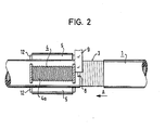
- Fig. 2 eine Aufsicht auf die außen zu beschälende und bereits teilweise beschälte Ader mit einigen Aggregaten des Rundschälgeräts in teilweise weggebrochener Aufsicht von oben.
- Fig. 1 shows a schematic cross section through a wire and a side view of a particularly preferred embodiment of the invention and
- Fig. 2 is a plan view of the outside to be peeled and already partially peeled core with some aggregates of the rotary peeling device in a partially broken top view.
Gemäß der Zeichnung stützt sich das Gerät 16 auf dem Außenumfang der Ader 1 mittels dreier Walzen, nämlich einer Vorschubwalze 4 und zweier Führungswalzen 5 ab. Dabei empfiehlt es sich, die Angriffsstelle 6 der Vorschubwalze 4 an der Ader 1,und die Führungsstellen 7 der Führungswalzen 5 an der Ader 1 möglichst gleichmäßig am Adernumfang zu verteilen, um eine gute zentrierende Wirkung zu erreichen. Sofern mit ein und demselben Rundschälgerät unterschiedliche Aderdurchmesser bearbeitet werden sollen, empfiehlt es sich, den freien Durchmesser, der durch die Angriffstelle 6 und die Führungsstellen 7 gebildet wird, dadurch veränderbar zu machen, daß der Abstand der Führungswalzen 5 voneinander bzw. von der Vorschubwalze 4 geändert wird. Dies geschieht bei dem vorliegenden Ausführungsbeispiel dadurch, daß der Gelenkbolzen 13 durch Verdrehen des Drehknopfes 17 zur Adernachse hin verschoben werden kann. Auf dem Gelenkbolzen 13 sind die Bügel 12 gelagert, welche die Führungswalzen 5 tragen. Die Führungsstifte 15 in den Schlitzen 14 der Bügel 12 sorgen für ein scherenartiges Auf- bzw. Zufahren, wodurch eine Zentrierung unabhängig vom Aderndurchmesser erfolgt.According to the drawing, the
Die Vorschubwalze 4 ist, wie besser aus Fig. 2 ersichtlich ist, am Außenumfang mit einem Außengewinde 4a versehen. Nach dem Einstechen der gewünschten Absetzkante wird die Vorschubwalze 4 mittels des Drehknopfes 19 und Verstellen des Gewindes 20 arretiert. Hierdurch wird beim Drehen des Rundschälgeräts auf die Ader 1 ein Vorschub erzeugt und die Ader 1 zum Kabelende hin in Schälrichtung A bis auf die in Fig. 2 schematisch dargestellte Tiefe 3 abgeschält.The feed roller 4, as can be seen more clearly from FIG. 2, is provided on the outer circumference with an external thread 4a. After the desired setting edge has been inserted, the feed roller 4 is locked by means of the
Zweckmäßig ist es, wenn der vom Schälmesser 8 abgetragene Span über einen Spanabführungskanal nach außen abgeführt wird, der zweckmäßigerweise vom Schälmesser 8 innerhalb der Messerführung 9, der Rändelmutter 10 und des Messerhalters 11 als Bohrung verläuft. Der Span tritt dann durch die Bohrung im Messerhalter 11 nach oben aus. Die Schnitttiefe des Schälmessers 8 wird durch Verstellen der Rändelmutter 10 und ein selbsthemmendes Gewinde auf dem Messerhalter 11 stufenlos eingestellt.It is expedient if the chip removed from the
Claims (9)
Applications Claiming Priority (2)
| Application Number | Priority Date | Filing Date | Title |
|---|---|---|---|
| DE3308197 | 1983-03-08 | ||
| DE19833308197 DE3308197C2 (en) | 1983-03-08 | 1983-03-08 | Round peeling tool for plastic-insulated electrical cables or wires |
Publications (2)
| Publication Number | Publication Date |
|---|---|
| EP0121680A2 true EP0121680A2 (en) | 1984-10-17 |
| EP0121680A3 EP0121680A3 (en) | 1985-11-13 |
Family
ID=6192857
Family Applications (1)
| Application Number | Title | Priority Date | Filing Date |
|---|---|---|---|
| EP84101336A Withdrawn EP0121680A3 (en) | 1983-03-08 | 1984-02-09 | Circular cutting device for plastic-insulated electrical cables or cores |
Country Status (3)
| Country | Link |
|---|---|
| EP (1) | EP0121680A3 (en) |
| DE (1) | DE3308197C2 (en) |
| DK (1) | DK99484A (en) |
Cited By (3)
| Publication number | Priority date | Publication date | Assignee | Title |
|---|---|---|---|---|
| US6311600B1 (en) | 1999-10-20 | 2001-11-06 | Hong Kong Polytechnic University | Electric power cable sheath cutter |
| CN103579959A (en) * | 2013-10-15 | 2014-02-12 | 国家电网公司 | Portable cable sheath layer stripping and cutting device |
| CN104037671A (en) * | 2014-04-30 | 2014-09-10 | 国网河南省电力公司焦作供电公司 | 110 kv cable main insulation electric molding cutter |
Family Cites Families (8)
| Publication number | Priority date | Publication date | Assignee | Title |
|---|---|---|---|---|
| DE152887C (en) * | ||||
| US3218709A (en) * | 1963-04-04 | 1965-11-23 | Union Carbide Corp | Cable sheath cutting device |
| FR2173819B1 (en) * | 1972-03-03 | 1975-10-24 | Pinchon Raymond | |
| DE2210910A1 (en) * | 1972-03-07 | 1973-09-27 | Kabel Metallwerke Ghh | DEVICE FOR STRIPPING THE END OF THE CONDUCTOR FROM POWERFUL CABLES |
| GB1458366A (en) * | 1973-04-26 | 1976-12-15 | Bieganski Z | Tools for cutting |
| DE7613740U1 (en) * | 1976-04-28 | 1976-10-28 | Schleifer, Werner, 4590 Cloppenburg | Cone cutter |
| DE3214479C2 (en) * | 1981-07-22 | 1986-05-15 | Siemens AG, 1000 Berlin und 8000 München | Hand tool for peeling off the outer sheath of electrical lines and cables |
| DE8211568U1 (en) * | 1982-04-22 | 1982-09-16 | Hadres Werkzeugfabrik Bodo Heinrich Habel, 6800 Mannheim | Device for peeling cables |
-
1983
- 1983-03-08 DE DE19833308197 patent/DE3308197C2/en not_active Expired
-
1984
- 1984-02-09 EP EP84101336A patent/EP0121680A3/en not_active Withdrawn
- 1984-02-24 DK DK99484A patent/DK99484A/en not_active Application Discontinuation
Cited By (4)
| Publication number | Priority date | Publication date | Assignee | Title |
|---|---|---|---|---|
| US6311600B1 (en) | 1999-10-20 | 2001-11-06 | Hong Kong Polytechnic University | Electric power cable sheath cutter |
| CN103579959A (en) * | 2013-10-15 | 2014-02-12 | 国家电网公司 | Portable cable sheath layer stripping and cutting device |
| CN103579959B (en) * | 2013-10-15 | 2016-02-10 | 国家电网公司 | A kind of portable cable restrictive coating pelling-cutting device |
| CN104037671A (en) * | 2014-04-30 | 2014-09-10 | 国网河南省电力公司焦作供电公司 | 110 kv cable main insulation electric molding cutter |
Also Published As
| Publication number | Publication date |
|---|---|
| DK99484D0 (en) | 1984-02-24 |
| DE3308197C2 (en) | 1988-06-16 |
| EP0121680A3 (en) | 1985-11-13 |
| DK99484A (en) | 1984-09-09 |
| DE3308197A1 (en) | 1984-09-20 |
Similar Documents
| Publication | Publication Date | Title |
|---|---|---|
| EP0070554B1 (en) | Hand-tool for removing the outer-sheath layer of electric lines and electric cables | |
| DE202014101596U1 (en) | Device for stripping coaxial cables | |
| DE102007019386A1 (en) | Dismantling tool for dismantling mini coaxial cable, has cutting knife engaged at cable and passed around cable by rotation of tool holder and layers of cable splitted, until stopper rests against block surface | |
| DE2232714B2 (en) | Device for stripping isolated cores in a multi-core electrical flat cable | |
| DE1765588A1 (en) | Device for cutting and simultaneous stepped stripping of coaxial cables | |
| EP0121680A2 (en) | Circular cutting device for plastic-insulated electrical cables or cores | |
| EP1086513B1 (en) | Connecting terminal | |
| DE1954415C3 (en) | Device for preparing a coaxial cable end for the attachment of a coaxial cable connector | |
| DE4327356A1 (en) | Device for stripping the insulation off braided conductors | |
| DE3611365C2 (en) | ||
| EP0222112B1 (en) | Cable-stripping device | |
| DE29509719U1 (en) | Insulating part for supporting and centering an inner conductor in an outer conductor | |
| EP0216020A2 (en) | Device to remove an end of a coaxial cable | |
| CH607389A5 (en) | Cable insulation stripper with three jaws | |
| DE3784892T2 (en) | Electric cable preparation tool. | |
| EP0841716B1 (en) | Method and apparatus for providing electrical connection between an installation equipment and an electrical conductor with a surrounding insulation | |
| EP3695944B1 (en) | Method and device for splitting of plate-shaped objects made of brittle materials | |
| DE4205066C2 (en) | Tool for peeling an outlet cone on cables, especially high-voltage cables | |
| DE69208235T2 (en) | Manufacturing process for cutting and pre-stripping cables and wire conductors and apparatus for carrying out the process | |
| DE2629208C3 (en) | Tool for radially cutting into the insulating sleeve of an optical fiber | |
| AT524372B1 (en) | DEVICE FOR STRIPPING A SHIELDED CABLE | |
| DE102022204819B3 (en) | Device and method for stripping flat wire in the manufacture of stator and rotor windings | |
| DE19515880C1 (en) | Conductor or cable insulation removal device | |
| DE3426322C2 (en) | Device for stripping jumper wires | |
| DE3248683C2 (en) |
Legal Events
| Date | Code | Title | Description |
|---|---|---|---|
| PUAI | Public reference made under article 153(3) epc to a published international application that has entered the european phase |
Free format text: ORIGINAL CODE: 0009012 |
|
| AK | Designated contracting states |
Designated state(s): AT CH LI NL SE |
|
| PUAL | Search report despatched |
Free format text: ORIGINAL CODE: 0009013 |
|
| AK | Designated contracting states |
Designated state(s): AT CH LI NL SE |
|
| 17P | Request for examination filed |
Effective date: 19851204 |
|
| 17Q | First examination report despatched |
Effective date: 19861029 |
|
| STAA | Information on the status of an ep patent application or granted ep patent |
Free format text: STATUS: THE APPLICATION IS DEEMED TO BE WITHDRAWN |
|
| 18D | Application deemed to be withdrawn |
Effective date: 19880830 |
|
| RIN1 | Information on inventor provided before grant (corrected) |
Inventor name: BECKER, FRANK, DIPL.-ING. Inventor name: BLANKENBURG, BERND, DR. ING. |