EP0121414B1 - Lamp - Google Patents
Lamp Download PDFInfo
- Publication number
- EP0121414B1 EP0121414B1 EP84302132A EP84302132A EP0121414B1 EP 0121414 B1 EP0121414 B1 EP 0121414B1 EP 84302132 A EP84302132 A EP 84302132A EP 84302132 A EP84302132 A EP 84302132A EP 0121414 B1 EP0121414 B1 EP 0121414B1
- Authority
- EP
- European Patent Office
- Prior art keywords
- lamp
- lamp unit
- handle
- unit
- lamp according
- Prior art date
- Legal status (The legal status is an assumption and is not a legal conclusion. Google has not performed a legal analysis and makes no representation as to the accuracy of the status listed.)
- Expired
Links
- 238000000465 moulding Methods 0.000 description 10
- 230000003287 optical effect Effects 0.000 description 5
- 125000006850 spacer group Chemical group 0.000 description 4
- 239000000428 dust Substances 0.000 description 3
- BQCADISMDOOEFD-UHFFFAOYSA-N Silver Chemical compound [Ag] BQCADISMDOOEFD-UHFFFAOYSA-N 0.000 description 2
- 239000004020 conductor Substances 0.000 description 2
- 238000010276 construction Methods 0.000 description 2
- 230000000694 effects Effects 0.000 description 2
- 210000003414 extremity Anatomy 0.000 description 2
- 229910052709 silver Inorganic materials 0.000 description 2
- 239000004332 silver Substances 0.000 description 2
- 238000007664 blowing Methods 0.000 description 1
- 238000004140 cleaning Methods 0.000 description 1
- 238000001816 cooling Methods 0.000 description 1
- 210000003811 finger Anatomy 0.000 description 1
- 239000011521 glass Substances 0.000 description 1
- 238000005286 illumination Methods 0.000 description 1
- 239000011810 insulating material Substances 0.000 description 1
- 210000003141 lower extremity Anatomy 0.000 description 1
- 230000013011 mating Effects 0.000 description 1
- 229910052751 metal Inorganic materials 0.000 description 1
- 239000002184 metal Substances 0.000 description 1
- 230000000717 retained effect Effects 0.000 description 1
- 238000001356 surgical procedure Methods 0.000 description 1
- 210000003813 thumb Anatomy 0.000 description 1
- 238000009423 ventilation Methods 0.000 description 1
- 230000000007 visual effect Effects 0.000 description 1
Images




Classifications
-
- F—MECHANICAL ENGINEERING; LIGHTING; HEATING; WEAPONS; BLASTING
- F21—LIGHTING
- F21V—FUNCTIONAL FEATURES OR DETAILS OF LIGHTING DEVICES OR SYSTEMS THEREOF; STRUCTURAL COMBINATIONS OF LIGHTING DEVICES WITH OTHER ARTICLES, NOT OTHERWISE PROVIDED FOR
- F21V21/00—Supporting, suspending, or attaching arrangements for lighting devices; Hand grips
- F21V21/14—Adjustable mountings
- F21V21/26—Pivoted arms
-
- F—MECHANICAL ENGINEERING; LIGHTING; HEATING; WEAPONS; BLASTING
- F21—LIGHTING
- F21V—FUNCTIONAL FEATURES OR DETAILS OF LIGHTING DEVICES OR SYSTEMS THEREOF; STRUCTURAL COMBINATIONS OF LIGHTING DEVICES WITH OTHER ARTICLES, NOT OTHERWISE PROVIDED FOR
- F21V21/00—Supporting, suspending, or attaching arrangements for lighting devices; Hand grips
- F21V21/14—Adjustable mountings
- F21V21/30—Pivoted housings or frames
-
- F—MECHANICAL ENGINEERING; LIGHTING; HEATING; WEAPONS; BLASTING
- F21—LIGHTING
- F21W—INDEXING SCHEME ASSOCIATED WITH SUBCLASSES F21K, F21L, F21S and F21V, RELATING TO USES OR APPLICATIONS OF LIGHTING DEVICES OR SYSTEMS
- F21W2131/00—Use or application of lighting devices or systems not provided for in codes F21W2102/00-F21W2121/00
- F21W2131/20—Lighting for medical use
- F21W2131/202—Lighting for medical use for dentistry
-
- F—MECHANICAL ENGINEERING; LIGHTING; HEATING; WEAPONS; BLASTING
- F21—LIGHTING
- F21W—INDEXING SCHEME ASSOCIATED WITH SUBCLASSES F21K, F21L, F21S and F21V, RELATING TO USES OR APPLICATIONS OF LIGHTING DEVICES OR SYSTEMS
- F21W2131/00—Use or application of lighting devices or systems not provided for in codes F21W2102/00-F21W2121/00
- F21W2131/20—Lighting for medical use
- F21W2131/205—Lighting for medical use for operating theatres
-
- Y—GENERAL TAGGING OF NEW TECHNOLOGICAL DEVELOPMENTS; GENERAL TAGGING OF CROSS-SECTIONAL TECHNOLOGIES SPANNING OVER SEVERAL SECTIONS OF THE IPC; TECHNICAL SUBJECTS COVERED BY FORMER USPC CROSS-REFERENCE ART COLLECTIONS [XRACs] AND DIGESTS
- Y10—TECHNICAL SUBJECTS COVERED BY FORMER USPC
- Y10S—TECHNICAL SUBJECTS COVERED BY FORMER USPC CROSS-REFERENCE ART COLLECTIONS [XRACs] AND DIGESTS
- Y10S362/00—Illumination
- Y10S362/804—Surgical or dental spotlight
Definitions
- An adjustable lamp unit comprising a lamp unit mounted on a support structure permitting translational movement of the lamp unit in a generally horizontal plane, the lamp unit being pivotable relative to the support structure about a generally vertical axis for azimuth adjustment of a light beam from the lamp unit, and a handle secured to the lamp unit; the lamp unit being disposed substantially entirely on one side of the vertical axis and the handle being disposed adjacent to the said axis on its other side; the lamp unit being rotatable to alter its handedness.
- Adjustable lamps are of particular interest for medical and dental applications, but they may of course be used in many other situations.
- FIG. 1 shows a typical lamp assembly for a dental surgery.
- a support structure comprises an articulated two part arm on a mounting 1 (which may be secured to the ceiling), a pair of articulated arm sections 2, 3 and a bracket 4 supporting a lamp 5.
- the joints between these members are pivoted for rotation about axes 6 and 7 to permit horizontal translational movement of the bracket 4 in any direction, whilst the second arm 3 is pivoted about axes 8 and 9 and spring-balanced for vertical movement with a parallelogram linkage (not shown) to maintain the bracket 4 in a vertical attitude.
- the bracket and hence the lamp can be translated to any desired position.
- the upper and lower ends of the bracket are pivotable relative to one another about a vertical axis 10.
- this arm system permits freedom of spatial location together with azimuth movement of the light. This leaves pitch movement of the light (about axis 11) to be provided within the light unit itself to complete the facility of universal spatial positioning combined with freedom to beam the light in any direction.
- the lamp 5 is fitted with handles 14, 15.
- the dentist if right handed will sit or stand on his patient's right and adjust the position and angle of the lamp by means of the right-hand handle 15. If he is left-handed. he will generally sit or stand on the opposite side and use the other handle 14.
- a lamp similar to that shown in Fig 1 is disclosed in British patent specification no. 872,681.
- United States patent no 4 097 919 describes an illumination system for use in hospitals and comprising a lamp unit similar to the one shown in Fig 1, but which has a single handle on the bottom of the unit, integral with the housing of the unit.
- British patent specification 1 259 767 describes a dental lamp and X-ray apparatus mounted in a common housing to project their beams in opposite directions. The housing is turned round when the dentist wishes to use the other beam to the one currently in use.
- EP-A-0 070 434 discloses an adjustable lamp comprising a lamp unit mounted on a support providing a plurality of rotational degrees of freedom for the lamp unit and a handle to enable the position of the lamp to be adjusted.
- the lamp according to the present invention is characterised in that the handle is attached to the lamp unit through a clutch unit which, when released, allows the handle to be rotationally adjusted relative to the lamp unit to alter its handedness relative thereto. This enables the handle to be set relative to the lamp unit to a desired position for ease of control of the lamp whatever the handedness of the lamp.
- a convenient arrangement is to provide that the lamp is disposed substantially entirely on one side of the pivot axis: the handle may then be disposed on the other side of the axis.
- the lamp can be made pivotable about a generally horizontal axis (usually desirable in any event for pitch adjustment). Then, if a sufficient degree of rotation of the lamp about vertical and horizontal axes is allowed for, it can be rotated through 180° about both axes to assume an attitude which is a mirror- image of its former position, thereby permitting adjustment from the other side.
- Figure 2 shows a general perspective view of a lamp body 5 disposed on one side of a bracket 16, whilst a handle 15 on the other side of the bracket 16 is secured to the lamp body 5 by a connection (described below) passing through a bearing in the lower part 17 of the bracket, so that, by means of the handle 15, the lamp body 5 can be rotated about a horizontal axis 11, for pitch adjustment of light beams from the lamp.
- the upper part 18 of the bracket forms a socket which engages the end 4 of a balanced support arm assembly; the end 4 including a bearing for rotation about vertical pivot axis 10.
- the support arm assembly could be as described above with reference to figure 1, or of any other suitable construction.
- the lamp housing is formed from two end mouldings 19a, 19b flanking a set of ribs 19c which form a ventilation grille.
- the mouldings are secured together by bolts extending between the two end mouldings 19a, 19b and through the ribs 19c.
- a front panel is fixed to the housing formed by the end moulding and the ribs.
- a tubular pivot 21 carries at its lower extremity a small two- track slip-ring 22 which is connected to an electrical supply by an electrical cable 23.
- the small slip-ring 22 retains a tapered swivel sleeve 24 that is free to rotate on the tubular pivot 21 and is constrained from excess axial movement by a part of the arm (not shown) that supports the tubular pivot 21.
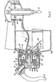
- the bracket 16 comprises a two piece moulded housing 25 and 26. The portions are shown cut away in figure 3. They have a joint line in the plane containing the axis 10 of the tubular pivot 21 and perpendicular to the axis 11 about which the lamp 5 rotates, these two axes being normal to each other.
- the upper ends of the moulded housing portions 25 and 26 have ribs which, when the two are fixed together, form a conical socket into which the tapered swivel sleeve 24 fits and where it is retained by a dowel 28 that has suitable locking means (not shown).
- ribs within the housing parts 25,26 retain a contact panel 29 that carries four leaf springs 30 each with a silver contact at its extremity and so arranged that two of these contacts press onto an inner silver plated track of the slip-ring 22 and the other two onto the outer such track.
- the slip-ring 22 may conveniently take the form of a printed-circuit disc.
- One conductor of the electrical cable 23 connects to the inner track and the other conductor to the outer track. Electrical current is collected by the contacts, one pole being passed via switch 31 to a cable 32 while the other pole is connected to a second cable 33.
- the switch 31 may comprise a touch-sensitive on/off switch and a rotatable knob controlling the voltage supplied to the lamp, and therefore the brightness of the lamp.
- the cables 32, 33 conduct current to and from the lamp housing.
- the cables are flexible and are loosely coiled around a spacer (described below).
- the cables pass to the lamp housing from the middle of the coil.
- the rotation of the lamp housing about the axis 11 is limited to a range of 270° and is accommodated by the cable coil tightening and loosening about the spacer.
- the rotation could be accommodated by using a second two- track slip ring transverse to the axis 11.
- Figure 4 is a horizontal section of the lamp housing at the axis 11, when the output light beams are horizontal.
- the end moulding 19a of the lamp housing has a generally cylindrical extension 38.
- a cup member 42, a tubular spacer 43 and a second cup member 44 are bolted to an integral bulkhead 40 formed by the end wall of the moulding 19a.
- the second cup member 44 has an internal serrated clutch surface 45, shown more clearly in figure 3.
- Bearing races 39 allow relative rotation of the cylindrical extension (and along with it the cup member 42) and the housing formed by the mouldings 25, 26.
- the flexible cables 32, 33 which conduct current between the slip ring and the lamp housing are coiled around the spacer 43 and extend from the middle of the coil to the lamp housing.
- the handle 15 is moulded with a domed disc 49 and carries an axial spigot 50 which is journelled in a tubular extension 42a of the cupped member 42.
- the spigot 50 extends through an aperture 41 in the moulding 19a.
- Adjacent the end of the spigot 50 is an annular groove 51 which is engaged by a notch in a lever 52 pivoted at 53, so that lever movement will retain or release the handle.
- a button headed recessed plunger 54 is incorporated into the handle and carries teeth 55 which can engage the serrated clutch surface 45 formed in the interior of the cup member 44. The teeth 55 are urged into engagement with the clutch surface 45 by a spring 56.
- the handle 15 is normally locked to the moulding 19a but by pressing the plunger 54 the handle can be angularly reset to any desired relationship with the moulding for ease of control of the light position and orientation.
- a felt dust seal 57 is provided against ingress of dust into the housing 25, 26.
- a spring-biased lever 58 bears on the felt seal 57 to urge the seal against the housing portion 26, to provide frictional resistance against rotation of the lamp housing.
- a lamp bulb 60 is carried on a plug-in mount 62.
- the bulb 60 may be introduced into the housing through an aperture 61 in the middle of the front panel 20.
- the mount 62 closes the aperture and is held in position in the aperture 61 by a latch (not shown).
- the mount 62 carries two flat prong electrodes 64 which are electrically connected to the bulb filament.
- the electrodes 64 mate with respective spring contacts 66 to which respective ones of the cables 32, 33 are connected.
- a grub screw 65 on the mount 62 sets the innermost position to which the mount 62 may be pushed.
- the optical housing 37 is shown cut in half in figure 5, at the plane of the section of figure 4.
- the illustrated half of the housing has four main portions. Firstly, half of the cylindrical extension 38, terminating at the bulkhead 40, secondly a near mirror compartment 61a, thirdly a central light source compartment 63 and fourthly a far mirror compartment 61 b.
- the ribs 19c form a grille in the curved "floor" of the compartments 63 extending between the two bulkheads which separate the three compartments.
- the grille allows a cooling air flow around the light source in the compartment 63.
- the two mirror compartments 61a, 61 each have mountings to support mirrors 67,68 which re-direct the light beams leaving the compartments 62 so they converge at a point on a line which is normal to the axis 11 of rotation of the optical housing and which intersects this axis midway between the two mirrors. This intersection point is also midway between the light source compartment bulkheads.
- the mirrors 67, 68 may be coated so as to reflect visual light but allow infra-red heat to pass straight through. If this is so a black metal heat sink would be located a short distance behind each mirror to disperse the heat and prevent a hot spot on the housing.
- the light source is shown in figure 6 and consists of a filament or discharge type bulb in a split reflector of the type which is the subject of EP-A-0 113 197.
- the bulb 60 (shown schematically) is arranged so that its filament 70 lies at the first focus point of the two curved reflector segments 71, 72 so that equal light beams are emitted from approximately parallel edged apertures 73 and 74 to converge at second focus points 75 and 76.
- the bulb 60 is mounted on a mount 62 made of insulating material, the bulb filament being connected to a pair of prong electrodes 64. Wires inside the mount 62 feed current to the filament 70.
- the segments 71,72 are cut away as required to allow access for the bulb and the mount.
- the mount 62 and the housing surfaces against which the mount locates are formed to ensure correct orientation of the filament and to form an abutment to ensure the filament is co-incident with the reflector focal point.
- non- circular integers and apertures may be used.
- the bulb 60 the reflector segments 71 and 72 and preferably the apertures 73 and 74 are carried in a heat conducting housing which can be finned on its exterior for adequate heat transfer by convected air flow through the housing grille.
- This heat conducting housing is mounted on the housing bulkheads by two rectangular light tunnels aligned with the mirrors 67, 68. These light tunnels may be closed at their extremities by glasses that diffuse the light and/or filter out heat from the beams.
- Figure 7 shows a lens support member 20 which forms the front of the lamp housing.
- the two lenses 82, 83 at the exit apertures of the housing are set at approx 7° toe-in angle to align with the axes of the converging beams.
- These lenses may either be of a spherical type or of a cylindrical type and may incorporate prisms. The requirements for the lenses and suitable lenses are described in the applicant's copending application referred to above.
- the lens support member 20 is fixed on the housing and may be removed to permit cleaning of lenses 82 and 83, of mirrors 67 and 68 and blowing off any dust around the finned lamp/ reflector housing. Removal also permits operation of the lever 52 for removal of the handle 15.
- the lenses 82, 83 are adjustably fixed in mounts. The alignment of the lenses 82,83 may be adjusted as required.
- the handle 15 used to manoeuvre and orientate the lamp is very close to the vertical swivel axis of the swivel sleeve 24 and thus the greater forces required to move the articulated support arm can be applied almost directly to the arm and not by the usual awkward thumb and finger couple as is necessary when the swivel axis is located centrally on the lamp.
Landscapes
- Engineering & Computer Science (AREA)
- General Engineering & Computer Science (AREA)
- Non-Portable Lighting Devices Or Systems Thereof (AREA)
- Vessels And Coating Films For Discharge Lamps (AREA)
- Securing Globes, Refractors, Reflectors Or The Like (AREA)
Applications Claiming Priority (2)
| Application Number | Priority Date | Filing Date | Title |
|---|---|---|---|
| GB838308693A GB8308693D0 (en) | 1983-03-29 | 1983-03-29 | Lamp |
| GB8308693 | 1983-03-29 |
Publications (2)
| Publication Number | Publication Date |
|---|---|
| EP0121414A1 EP0121414A1 (en) | 1984-10-10 |
| EP0121414B1 true EP0121414B1 (en) | 1988-07-20 |
Family
ID=10540445
Family Applications (1)
| Application Number | Title | Priority Date | Filing Date |
|---|---|---|---|
| EP84302132A Expired EP0121414B1 (en) | 1983-03-29 | 1984-03-29 | Lamp |
Country Status (10)
| Country | Link |
|---|---|
| US (1) | US4581689A (https=) |
| EP (1) | EP0121414B1 (https=) |
| JP (1) | JPS60500930A (https=) |
| KR (1) | KR900005290B1 (https=) |
| AU (1) | AU564547B2 (https=) |
| DE (1) | DE3472828D1 (https=) |
| GB (1) | GB8308693D0 (https=) |
| HK (1) | HK18689A (https=) |
| IN (1) | IN163631B (https=) |
| WO (1) | WO1984003931A1 (https=) |
Families Citing this family (35)
| Publication number | Priority date | Publication date | Assignee | Title |
|---|---|---|---|---|
| DE3506864A1 (de) * | 1985-02-27 | 1985-07-18 | BON-Design Jytte Kuhberg, 2362 Wahlstedt | Verstellbare halterung fuer haengende deckenleuchten |
| USD303719S (en) | 1986-04-10 | 1989-09-26 | Prescolite Inc. | Adjustable directional lighting fixture or similar article |
| USD296013S (en) | 1986-05-27 | 1988-05-31 | Cooper Industries | Track lighting fixture |
| USD298656S (en) | 1986-08-07 | 1988-11-22 | Kidde Consumer Durables Corporation | Floodlight housing |
| AU107783S (en) | 1989-03-28 | 1990-06-05 | Emi Plc Thorn | Lamp fitting |
| USD319702S (en) | 1989-07-28 | 1991-09-03 | Lighting Services, Inc. | Adjustable lighting fixture |
| US5097400A (en) * | 1991-03-29 | 1992-03-17 | Luxo Lamp Corporation | Halogen lamp |
| DE69227687T2 (de) * | 1991-06-25 | 1999-04-22 | Alm, Ardon | Medizinischer apparat zur beleuchtung eines behandlungsbereiches |
| GB2262335B (en) * | 1991-12-11 | 1995-06-14 | Astley Designs Ltd | Light assembly |
| US5562344A (en) * | 1994-02-10 | 1996-10-08 | Mdt Corporation | Handle for dental light |
| DE29706140U1 (de) * | 1997-04-07 | 1997-05-22 | Eickhorst & Co, 22453 Hamburg | Schwenkarmleuchte |
| DE19744638C2 (de) * | 1997-10-09 | 1999-11-04 | Zumtobel Staff Gmbh & Co Kg | Leuchte |
| US6132062A (en) * | 1998-03-27 | 2000-10-17 | Hill-Rom, Inc. | Task light for a surgical light apparatus |
| USD414888S (en) | 1998-11-12 | 1999-10-05 | Vari-Lite, Inc. | Adjustable compact luminaire |
| FR2792996B1 (fr) * | 1999-04-28 | 2001-07-13 | Alm | Butee souple de limitation de course angulaire, systeme articule comprenant une telle butee, et equipement medical comportant un tel systeme articule |
| JP4133834B2 (ja) | 2002-02-25 | 2008-08-13 | ステリス インコーポレイテッド | 無影灯のための周辺照明システム |
| US20050242261A1 (en) * | 2002-02-25 | 2005-11-03 | Steris Inc | Surgical suspension system |
| JP4113974B2 (ja) * | 2002-02-25 | 2008-07-09 | ステリス インコーポレイテッド | 外科用懸吊システム |
| JP4133835B2 (ja) * | 2002-02-25 | 2008-08-13 | ステリス インコーポレイテッド | 外科用照明システムにおけるエルゴノミック制御 |
| USD543937S1 (en) | 2005-01-04 | 2007-06-05 | Discus Dental Impressions, Inc. | Power pack for dentistry applications |
| USD542947S1 (en) | 2005-01-04 | 2007-05-15 | Discus Dental Impressions, Inc. | Lamp for dentistry applications |
| DE202005010321U1 (de) * | 2004-07-02 | 2006-01-05 | Discus Dental Impressions Inc., Culver City | Beleuchtungssystem für zahnärztliche Anwendungen |
| USD538960S1 (en) | 2005-01-04 | 2007-03-20 | Discus Dental Impressions, Inc. | Support structure for dentistry applications |
| USD538459S1 (en) | 2005-01-04 | 2007-03-13 | Discus Dental Impressions, Inc. | Support structure for a lamp for dentistry applications |
| USD537192S1 (en) | 2005-01-04 | 2007-02-20 | Discus Dental Impressions, Inc. | Light guide for dentistry applications |
| USD539956S1 (en) | 2005-01-04 | 2007-04-03 | Discus Dental Impressions, Inc. | Support structure for dentistry applications |
| US7997759B2 (en) * | 2008-03-03 | 2011-08-16 | Designs For Vision, Inc. | Illumination device |
| US7682042B2 (en) * | 2008-04-23 | 2010-03-23 | Designs For Vision, Inc. | Illumination device |
| DE502008001126D1 (de) * | 2008-06-20 | 2010-09-23 | Trumpf Medizin Systeme Gmbh & Co Kg | Operationsleuchte mit Aufhängevorrichtung |
| US8564947B2 (en) * | 2010-02-12 | 2013-10-22 | Electronics And Telecommunications Research Institute | Heat exhaustion structure for heat dissipating device |
| US9687305B2 (en) * | 2011-01-14 | 2017-06-27 | Ondal Holding Gmbh | Lighting device |
| CN102606946A (zh) * | 2012-02-27 | 2012-07-25 | 苏州卫生职业技术学院 | 一种主辅式手术室无影灯 |
| CN111828940B (zh) * | 2019-04-19 | 2022-05-31 | 明基三丰医疗器材股份有限公司 | 可调整高度的支撑臂结构 |
| CN111142573B (zh) * | 2019-12-27 | 2023-06-13 | 兰州空间技术物理研究所 | 一种空间微重力环境下的二维转台伴随投光照明设备 |
| US11015788B1 (en) * | 2020-10-05 | 2021-05-25 | Abl Ip Holding Llc | Light fixture with integral handle |
Citations (1)
| Publication number | Priority date | Publication date | Assignee | Title |
|---|---|---|---|---|
| EP0070434A1 (de) * | 1981-07-17 | 1983-01-26 | Siemens Aktiengesellschaft | Höhenverstellbarer Parallelogrammtragarm |
Family Cites Families (18)
| Publication number | Priority date | Publication date | Assignee | Title |
|---|---|---|---|---|
| US1598606A (en) * | 1924-08-21 | 1926-09-07 | Gen Optical Company Inc | Illuminating device for ophthalmological apparatus |
| US1909947A (en) * | 1929-02-06 | 1933-05-23 | Ernest H Greppin | Operating room lighting fixture |
| US2164390A (en) * | 1938-06-10 | 1939-07-04 | Faries Mfg Co | Joint for dental brackets |
| US2215635A (en) * | 1939-06-03 | 1940-09-24 | Westinghouse X Ray Co Inc | Hospital sterilizing unit and control |
| GB872681A (en) * | 1958-02-05 | 1961-07-12 | Ritter Co Inc | Dental light |
| US3075071A (en) * | 1958-09-04 | 1963-01-22 | Ritter Co Inc | Sterilizable focusing means for surgical lights |
| DE1193897B (de) * | 1961-12-04 | 1965-06-03 | Quarzlampen Gmbh | Operationsleuchte mit Schwenkarm |
| SE330588B (https=) * | 1969-04-22 | 1970-11-23 | S Lundin | |
| JPS5650413B2 (https=) * | 1974-04-16 | 1981-11-28 | ||
| US4097919A (en) * | 1975-10-24 | 1978-06-27 | Emerson Electric Co. | Illumination system |
| JPS53873A (en) * | 1976-06-23 | 1978-01-07 | Mitsubishi Electric Corp | Fluid blowwout breaker |
| JPS5427106U (https=) * | 1977-07-25 | 1979-02-22 | ||
| IT1086170B (it) * | 1977-07-28 | 1985-05-28 | Iguzzini Spa | Supporto a bracci articolati,in particolare per lampade |
| SU719085A1 (ru) * | 1977-12-15 | 1981-09-07 | Предприятие П/Я В-2156 | Плавучий кран |
| JPS5522643U (https=) * | 1978-07-31 | 1980-02-14 | ||
| CA1124219A (en) * | 1979-06-11 | 1982-05-25 | Isao Yamada | Lighting fixture for use in medical operations and therapeutic treatment |
| JPS58155701U (ja) * | 1982-04-14 | 1983-10-18 | 小糸工業株式会社 | 無影灯用反射鏡 |
| US4463413A (en) * | 1983-08-29 | 1984-07-31 | Shirley Howard L | Adjustable photographic light stand |
-
1983
- 1983-03-29 GB GB838308693A patent/GB8308693D0/en active Pending
-
1984
- 1984-03-28 KR KR1019840001613A patent/KR900005290B1/ko not_active Expired
- 1984-03-28 IN IN204/MAS/84A patent/IN163631B/en unknown
- 1984-03-29 AU AU28109/84A patent/AU564547B2/en not_active Ceased
- 1984-03-29 US US06/673,705 patent/US4581689A/en not_active Expired - Fee Related
- 1984-03-29 EP EP84302132A patent/EP0121414B1/en not_active Expired
- 1984-03-29 WO PCT/GB1984/000107 patent/WO1984003931A1/en not_active Ceased
- 1984-03-29 DE DE8484302132T patent/DE3472828D1/de not_active Expired
- 1984-03-29 JP JP59501470A patent/JPS60500930A/ja active Granted
-
1989
- 1989-03-02 HK HK186/89A patent/HK18689A/en not_active IP Right Cessation
Patent Citations (1)
| Publication number | Priority date | Publication date | Assignee | Title |
|---|---|---|---|---|
| EP0070434A1 (de) * | 1981-07-17 | 1983-01-26 | Siemens Aktiengesellschaft | Höhenverstellbarer Parallelogrammtragarm |
Also Published As
| Publication number | Publication date |
|---|---|
| GB8308693D0 (en) | 1983-05-05 |
| WO1984003931A1 (en) | 1984-10-11 |
| EP0121414A1 (en) | 1984-10-10 |
| KR900005290B1 (ko) | 1990-07-27 |
| US4581689A (en) | 1986-04-08 |
| IN163631B (https=) | 1988-10-22 |
| JPH0421282B2 (https=) | 1992-04-09 |
| DE3472828D1 (en) | 1988-08-25 |
| HK18689A (en) | 1989-03-10 |
| AU564547B2 (en) | 1987-08-13 |
| JPS60500930A (ja) | 1985-06-20 |
| AU2810984A (en) | 1984-10-25 |
| KR840008491A (ko) | 1984-12-15 |
Similar Documents
| Publication | Publication Date | Title |
|---|---|---|
| EP0121414B1 (en) | Lamp | |
| US4797736A (en) | Head mounted illumination and camera assembly | |
| US5335159A (en) | Plastic lamp holder | |
| CA1057717A (en) | Focusing device for sealed type multi-lamp for obtaining shadowless illumination | |
| AU758244B2 (en) | Fiber optic ceiling supported surgical task light system with optical commutator and manual zoom lens | |
| US3528424A (en) | Laser surgical knife equipment | |
| CA1103633A (en) | Vehicle headlamp and mounting assembly | |
| US4104709A (en) | Surgeons headlight with continuously variable spot size | |
| US4392183A (en) | Device in connection with cameras | |
| US6462867B2 (en) | Monocular mounting for multi-channel panoramic night vision goggle having an angled mounting shoe | |
| US4531813A (en) | Overhead viewing mirror apparatus for bedridden and paralyzed persons | |
| US4978306A (en) | Snap-apart universal jointed electrical connection | |
| JPS5926084B2 (ja) | 照明器具 | |
| US20220167703A1 (en) | Viewing Device Mount Employing Laterally Rotating Mechanism | |
| JP2622692B2 (ja) | カメラ等用のパンナ | |
| US4290422A (en) | Surgical headlight system | |
| AU783936B2 (en) | Viewfinder for high definition video camera | |
| JPS5933885B2 (ja) | 観察装置用継手 | |
| EP0270597B1 (en) | Surgical operating room lamp or similar lamp | |
| US4916597A (en) | Lighthead assembly | |
| AU621724B2 (en) | Light fitting | |
| US2883980A (en) | Physician's headlight | |
| KR900005706Y1 (ko) | 의료용 조명등의 초점 조절장치 | |
| JPS6236168Y2 (https=) | ||
| CA1297462C (en) | Head mounted illumination and camera assembly |
Legal Events
| Date | Code | Title | Description |
|---|---|---|---|
| PUAI | Public reference made under article 153(3) epc to a published international application that has entered the european phase |
Free format text: ORIGINAL CODE: 0009012 |
|
| AK | Designated contracting states |
Designated state(s): DE FR GB IT NL SE |
|
| 17P | Request for examination filed |
Effective date: 19850403 |
|
| 17Q | First examination report despatched |
Effective date: 19860417 |
|
| GRAA | (expected) grant |
Free format text: ORIGINAL CODE: 0009210 |
|
| ITF | It: translation for a ep patent filed | ||
| AK | Designated contracting states |
Kind code of ref document: B1 Designated state(s): DE FR GB IT NL SE |
|
| REF | Corresponds to: |
Ref document number: 3472828 Country of ref document: DE Date of ref document: 19880825 |
|
| ET | Fr: translation filed | ||
| PLBE | No opposition filed within time limit |
Free format text: ORIGINAL CODE: 0009261 |
|
| STAA | Information on the status of an ep patent application or granted ep patent |
Free format text: STATUS: NO OPPOSITION FILED WITHIN TIME LIMIT |
|
| 26N | No opposition filed | ||
| ITTA | It: last paid annual fee | ||
| PGFP | Annual fee paid to national office [announced via postgrant information from national office to epo] |
Ref country code: NL Payment date: 19920331 Year of fee payment: 9 |
|
| PG25 | Lapsed in a contracting state [announced via postgrant information from national office to epo] |
Ref country code: NL Effective date: 19931001 |
|
| NLV4 | Nl: lapsed or anulled due to non-payment of the annual fee | ||
| EAL | Se: european patent in force in sweden |
Ref document number: 84302132.0 |
|
| PGFP | Annual fee paid to national office [announced via postgrant information from national office to epo] |
Ref country code: SE Payment date: 19960325 Year of fee payment: 13 |
|
| PGFP | Annual fee paid to national office [announced via postgrant information from national office to epo] |
Ref country code: GB Payment date: 19960327 Year of fee payment: 13 Ref country code: FR Payment date: 19960327 Year of fee payment: 13 |
|
| PGFP | Annual fee paid to national office [announced via postgrant information from national office to epo] |
Ref country code: DE Payment date: 19960425 Year of fee payment: 13 |
|
| PG25 | Lapsed in a contracting state [announced via postgrant information from national office to epo] |
Ref country code: GB Effective date: 19970329 |
|
| PG25 | Lapsed in a contracting state [announced via postgrant information from national office to epo] |
Ref country code: SE Effective date: 19970330 |
|
| GBPC | Gb: european patent ceased through non-payment of renewal fee |
Effective date: 19970329 |
|
| PG25 | Lapsed in a contracting state [announced via postgrant information from national office to epo] |
Ref country code: FR Free format text: LAPSE BECAUSE OF NON-PAYMENT OF DUE FEES Effective date: 19971128 |
|
| PG25 | Lapsed in a contracting state [announced via postgrant information from national office to epo] |
Ref country code: DE Effective date: 19971202 |
|
| EUG | Se: european patent has lapsed |
Ref document number: 84302132.0 |
|
| REG | Reference to a national code |
Ref country code: FR Ref legal event code: ST |