EP0121207A2 - Hollow plastic body - Google Patents
Hollow plastic body Download PDFInfo
- Publication number
- EP0121207A2 EP0121207A2 EP84103307A EP84103307A EP0121207A2 EP 0121207 A2 EP0121207 A2 EP 0121207A2 EP 84103307 A EP84103307 A EP 84103307A EP 84103307 A EP84103307 A EP 84103307A EP 0121207 A2 EP0121207 A2 EP 0121207A2
- Authority
- EP
- European Patent Office
- Prior art keywords
- plastic
- shells
- hollow body
- flanges
- joints
- Prior art date
- Legal status (The legal status is an assumption and is not a legal conclusion. Google has not performed a legal analysis and makes no representation as to the accuracy of the status listed.)
- Withdrawn
Links
Images

Classifications
-
- F—MECHANICAL ENGINEERING; LIGHTING; HEATING; WEAPONS; BLASTING
- F02—COMBUSTION ENGINES; HOT-GAS OR COMBUSTION-PRODUCT ENGINE PLANTS
- F02M—SUPPLYING COMBUSTION ENGINES IN GENERAL WITH COMBUSTIBLE MIXTURES OR CONSTITUENTS THEREOF
- F02M35/00—Combustion-air cleaners, air intakes, intake silencers, or induction systems specially adapted for, or arranged on, internal-combustion engines
- F02M35/10—Air intakes; Induction systems
- F02M35/1034—Manufacturing and assembling intake systems
- F02M35/10347—Moulding, casting or the like
-
- B—PERFORMING OPERATIONS; TRANSPORTING
- B29—WORKING OF PLASTICS; WORKING OF SUBSTANCES IN A PLASTIC STATE IN GENERAL
- B29C—SHAPING OR JOINING OF PLASTICS; SHAPING OF MATERIAL IN A PLASTIC STATE, NOT OTHERWISE PROVIDED FOR; AFTER-TREATMENT OF THE SHAPED PRODUCTS, e.g. REPAIRING
- B29C45/00—Injection moulding, i.e. forcing the required volume of moulding material through a nozzle into a closed mould; Apparatus therefor
- B29C45/14—Injection moulding, i.e. forcing the required volume of moulding material through a nozzle into a closed mould; Apparatus therefor incorporating preformed parts or layers, e.g. injection moulding around inserts or for coating articles
- B29C45/14467—Joining articles or parts of a single article
-
- B—PERFORMING OPERATIONS; TRANSPORTING
- B29—WORKING OF PLASTICS; WORKING OF SUBSTANCES IN A PLASTIC STATE IN GENERAL
- B29C—SHAPING OR JOINING OF PLASTICS; SHAPING OF MATERIAL IN A PLASTIC STATE, NOT OTHERWISE PROVIDED FOR; AFTER-TREATMENT OF THE SHAPED PRODUCTS, e.g. REPAIRING
- B29C65/00—Joining or sealing of preformed parts, e.g. welding of plastics materials; Apparatus therefor
- B29C65/02—Joining or sealing of preformed parts, e.g. welding of plastics materials; Apparatus therefor by heating, with or without pressure
- B29C65/40—Applying molten plastics, e.g. hot melt
- B29C65/42—Applying molten plastics, e.g. hot melt between pre-assembled parts
-
- B—PERFORMING OPERATIONS; TRANSPORTING
- B29—WORKING OF PLASTICS; WORKING OF SUBSTANCES IN A PLASTIC STATE IN GENERAL
- B29C—SHAPING OR JOINING OF PLASTICS; SHAPING OF MATERIAL IN A PLASTIC STATE, NOT OTHERWISE PROVIDED FOR; AFTER-TREATMENT OF THE SHAPED PRODUCTS, e.g. REPAIRING
- B29C65/00—Joining or sealing of preformed parts, e.g. welding of plastics materials; Apparatus therefor
- B29C65/48—Joining or sealing of preformed parts, e.g. welding of plastics materials; Apparatus therefor using adhesives, i.e. using supplementary joining material; solvent bonding
- B29C65/4805—Joining or sealing of preformed parts, e.g. welding of plastics materials; Apparatus therefor using adhesives, i.e. using supplementary joining material; solvent bonding characterised by the type of adhesives
- B29C65/481—Non-reactive adhesives, e.g. physically hardening adhesives
- B29C65/4815—Hot melt adhesives, e.g. thermoplastic adhesives
-
- B—PERFORMING OPERATIONS; TRANSPORTING
- B29—WORKING OF PLASTICS; WORKING OF SUBSTANCES IN A PLASTIC STATE IN GENERAL
- B29C—SHAPING OR JOINING OF PLASTICS; SHAPING OF MATERIAL IN A PLASTIC STATE, NOT OTHERWISE PROVIDED FOR; AFTER-TREATMENT OF THE SHAPED PRODUCTS, e.g. REPAIRING
- B29C65/00—Joining or sealing of preformed parts, e.g. welding of plastics materials; Apparatus therefor
- B29C65/48—Joining or sealing of preformed parts, e.g. welding of plastics materials; Apparatus therefor using adhesives, i.e. using supplementary joining material; solvent bonding
- B29C65/52—Joining or sealing of preformed parts, e.g. welding of plastics materials; Apparatus therefor using adhesives, i.e. using supplementary joining material; solvent bonding characterised by the way of applying the adhesive
- B29C65/54—Joining or sealing of preformed parts, e.g. welding of plastics materials; Apparatus therefor using adhesives, i.e. using supplementary joining material; solvent bonding characterised by the way of applying the adhesive between pre-assembled parts
- B29C65/542—Joining or sealing of preformed parts, e.g. welding of plastics materials; Apparatus therefor using adhesives, i.e. using supplementary joining material; solvent bonding characterised by the way of applying the adhesive between pre-assembled parts by injection
-
- B—PERFORMING OPERATIONS; TRANSPORTING
- B29—WORKING OF PLASTICS; WORKING OF SUBSTANCES IN A PLASTIC STATE IN GENERAL
- B29C—SHAPING OR JOINING OF PLASTICS; SHAPING OF MATERIAL IN A PLASTIC STATE, NOT OTHERWISE PROVIDED FOR; AFTER-TREATMENT OF THE SHAPED PRODUCTS, e.g. REPAIRING
- B29C65/00—Joining or sealing of preformed parts, e.g. welding of plastics materials; Apparatus therefor
- B29C65/70—Joining or sealing of preformed parts, e.g. welding of plastics materials; Apparatus therefor by moulding
-
- B—PERFORMING OPERATIONS; TRANSPORTING
- B29—WORKING OF PLASTICS; WORKING OF SUBSTANCES IN A PLASTIC STATE IN GENERAL
- B29C—SHAPING OR JOINING OF PLASTICS; SHAPING OF MATERIAL IN A PLASTIC STATE, NOT OTHERWISE PROVIDED FOR; AFTER-TREATMENT OF THE SHAPED PRODUCTS, e.g. REPAIRING
- B29C66/00—General aspects of processes or apparatus for joining preformed parts
- B29C66/50—General aspects of joining tubular articles; General aspects of joining long products, i.e. bars or profiled elements; General aspects of joining single elements to tubular articles, hollow articles or bars; General aspects of joining several hollow-preforms to form hollow or tubular articles
- B29C66/51—Joining tubular articles, profiled elements or bars; Joining single elements to tubular articles, hollow articles or bars; Joining several hollow-preforms to form hollow or tubular articles
- B29C66/54—Joining several hollow-preforms, e.g. half-shells, to form hollow articles, e.g. for making balls, containers; Joining several hollow-preforms, e.g. half-cylinders, to form tubular articles
- B29C66/547—Joining several hollow-preforms, e.g. half-cylinders, to form tubular articles, e.g. endless tubes
- B29C66/5474—Joining several hollow-preforms, e.g. half-cylinders, to form tubular articles, e.g. endless tubes for making fork-shaped pieces, i.e. with 3 branches, e.g. Y-shaped pieces
-
- F—MECHANICAL ENGINEERING; LIGHTING; HEATING; WEAPONS; BLASTING
- F02—COMBUSTION ENGINES; HOT-GAS OR COMBUSTION-PRODUCT ENGINE PLANTS
- F02M—SUPPLYING COMBUSTION ENGINES IN GENERAL WITH COMBUSTIBLE MIXTURES OR CONSTITUENTS THEREOF
- F02M35/00—Combustion-air cleaners, air intakes, intake silencers, or induction systems specially adapted for, or arranged on, internal-combustion engines
- F02M35/10—Air intakes; Induction systems
- F02M35/10314—Materials for intake systems
- F02M35/10321—Plastics; Composites; Rubbers
-
- F—MECHANICAL ENGINEERING; LIGHTING; HEATING; WEAPONS; BLASTING
- F02—COMBUSTION ENGINES; HOT-GAS OR COMBUSTION-PRODUCT ENGINE PLANTS
- F02M—SUPPLYING COMBUSTION ENGINES IN GENERAL WITH COMBUSTIBLE MIXTURES OR CONSTITUENTS THEREOF
- F02M35/00—Combustion-air cleaners, air intakes, intake silencers, or induction systems specially adapted for, or arranged on, internal-combustion engines
- F02M35/10—Air intakes; Induction systems
- F02M35/1034—Manufacturing and assembling intake systems
- F02M35/10354—Joining multiple sections together
- F02M35/1036—Joining multiple sections together by welding, bonding or the like
-
- B—PERFORMING OPERATIONS; TRANSPORTING
- B29—WORKING OF PLASTICS; WORKING OF SUBSTANCES IN A PLASTIC STATE IN GENERAL
- B29C—SHAPING OR JOINING OF PLASTICS; SHAPING OF MATERIAL IN A PLASTIC STATE, NOT OTHERWISE PROVIDED FOR; AFTER-TREATMENT OF THE SHAPED PRODUCTS, e.g. REPAIRING
- B29C45/00—Injection moulding, i.e. forcing the required volume of moulding material through a nozzle into a closed mould; Apparatus therefor
- B29C45/14—Injection moulding, i.e. forcing the required volume of moulding material through a nozzle into a closed mould; Apparatus therefor incorporating preformed parts or layers, e.g. injection moulding around inserts or for coating articles
- B29C45/14467—Joining articles or parts of a single article
- B29C2045/14524—Joining articles or parts of a single article making hollow articles
-
- B—PERFORMING OPERATIONS; TRANSPORTING
- B29—WORKING OF PLASTICS; WORKING OF SUBSTANCES IN A PLASTIC STATE IN GENERAL
- B29C—SHAPING OR JOINING OF PLASTICS; SHAPING OF MATERIAL IN A PLASTIC STATE, NOT OTHERWISE PROVIDED FOR; AFTER-TREATMENT OF THE SHAPED PRODUCTS, e.g. REPAIRING
- B29C45/00—Injection moulding, i.e. forcing the required volume of moulding material through a nozzle into a closed mould; Apparatus therefor
-
- B—PERFORMING OPERATIONS; TRANSPORTING
- B29—WORKING OF PLASTICS; WORKING OF SUBSTANCES IN A PLASTIC STATE IN GENERAL
- B29C—SHAPING OR JOINING OF PLASTICS; SHAPING OF MATERIAL IN A PLASTIC STATE, NOT OTHERWISE PROVIDED FOR; AFTER-TREATMENT OF THE SHAPED PRODUCTS, e.g. REPAIRING
- B29C66/00—General aspects of processes or apparatus for joining preformed parts
- B29C66/70—General aspects of processes or apparatus for joining preformed parts characterised by the composition, physical properties or the structure of the material of the parts to be joined; Joining with non-plastics material
- B29C66/71—General aspects of processes or apparatus for joining preformed parts characterised by the composition, physical properties or the structure of the material of the parts to be joined; Joining with non-plastics material characterised by the composition of the plastics material of the parts to be joined
-
- B—PERFORMING OPERATIONS; TRANSPORTING
- B29—WORKING OF PLASTICS; WORKING OF SUBSTANCES IN A PLASTIC STATE IN GENERAL
- B29C—SHAPING OR JOINING OF PLASTICS; SHAPING OF MATERIAL IN A PLASTIC STATE, NOT OTHERWISE PROVIDED FOR; AFTER-TREATMENT OF THE SHAPED PRODUCTS, e.g. REPAIRING
- B29C66/00—General aspects of processes or apparatus for joining preformed parts
- B29C66/70—General aspects of processes or apparatus for joining preformed parts characterised by the composition, physical properties or the structure of the material of the parts to be joined; Joining with non-plastics material
- B29C66/72—General aspects of processes or apparatus for joining preformed parts characterised by the composition, physical properties or the structure of the material of the parts to be joined; Joining with non-plastics material characterised by the structure of the material of the parts to be joined
- B29C66/721—Fibre-reinforced materials
- B29C66/7212—Fibre-reinforced materials characterised by the composition of the fibres
-
- B—PERFORMING OPERATIONS; TRANSPORTING
- B29—WORKING OF PLASTICS; WORKING OF SUBSTANCES IN A PLASTIC STATE IN GENERAL
- B29L—INDEXING SCHEME ASSOCIATED WITH SUBCLASS B29C, RELATING TO PARTICULAR ARTICLES
- B29L2023/00—Tubular articles
- B29L2023/22—Tubes or pipes, i.e. rigid
-
- B—PERFORMING OPERATIONS; TRANSPORTING
- B29—WORKING OF PLASTICS; WORKING OF SUBSTANCES IN A PLASTIC STATE IN GENERAL
- B29L—INDEXING SCHEME ASSOCIATED WITH SUBCLASS B29C, RELATING TO PARTICULAR ARTICLES
- B29L2031/00—Other particular articles
- B29L2031/30—Vehicles, e.g. ships or aircraft, or body parts thereof
- B29L2031/3002—Superstructures characterized by combining metal and plastics, i.e. hybrid parts
-
- B—PERFORMING OPERATIONS; TRANSPORTING
- B29—WORKING OF PLASTICS; WORKING OF SUBSTANCES IN A PLASTIC STATE IN GENERAL
- B29L—INDEXING SCHEME ASSOCIATED WITH SUBCLASS B29C, RELATING TO PARTICULAR ARTICLES
- B29L2031/00—Other particular articles
- B29L2031/30—Vehicles, e.g. ships or aircraft, or body parts thereof
- B29L2031/3055—Cars
-
- F—MECHANICAL ENGINEERING; LIGHTING; HEATING; WEAPONS; BLASTING
- F05—INDEXING SCHEMES RELATING TO ENGINES OR PUMPS IN VARIOUS SUBCLASSES OF CLASSES F01-F04
- F05C—INDEXING SCHEME RELATING TO MATERIALS, MATERIAL PROPERTIES OR MATERIAL CHARACTERISTICS FOR MACHINES, ENGINES OR PUMPS OTHER THAN NON-POSITIVE-DISPLACEMENT MACHINES OR ENGINES
- F05C2225/00—Synthetic polymers, e.g. plastics; Rubber
- F05C2225/08—Thermoplastics
-
- Y—GENERAL TAGGING OF NEW TECHNOLOGICAL DEVELOPMENTS; GENERAL TAGGING OF CROSS-SECTIONAL TECHNOLOGIES SPANNING OVER SEVERAL SECTIONS OF THE IPC; TECHNICAL SUBJECTS COVERED BY FORMER USPC CROSS-REFERENCE ART COLLECTIONS [XRACs] AND DIGESTS
- Y10—TECHNICAL SUBJECTS COVERED BY FORMER USPC
- Y10T—TECHNICAL SUBJECTS COVERED BY FORMER US CLASSIFICATION
- Y10T428/00—Stock material or miscellaneous articles
- Y10T428/13—Hollow or container type article [e.g., tube, vase, etc.]
- Y10T428/1352—Polymer or resin containing [i.e., natural or synthetic]
- Y10T428/1397—Single layer [continuous layer]
Definitions
- the invention relates to a method for producing hollow bodies made of plastics, in particular with an at least partially expanding contour and / or axially curved cavity.
- plastic intake manifold that is injected in one shot, the lost cores e.g. subsequently removed from low-melting bismuth alloys (e.g. 138 ° C) or water-soluble salts.
- the invention has for its object to find a housing part, the interior of which widens from the access and / or is deflected to one or more sides, which is easy to manufacture, a tall shape has accuracy in the final state, has a high level of tightness, is fluidly favorable to design with little material and still has high strength.
- the object is achieved in that at least two prefabricated shells are pressed together in the warm state to form a hollow body with simultaneous exact shape specification at the joints, which are then connected by a plastic added under injection molding.
- the process makes it possible to manufacture even complex spatial hollow bodies, such as, for example, multi-curved, undercut intake manifolds of automobiles or with undercut cavities, in individual shells according to technically proven processes, in order to then connect them to melted plastic by injection molding.
- the distortion which occurs easily in multi-dimensional injection molded parts, can be compensated for, and secondly, the shells can be shaped or re-formed, so that the dimensions required for hydraulic or pneumatic reasons must be adhered to exactly.
- This advantage is further supported by the fact that individual shells are to be produced with a very smooth surface in terms of production technology, as a result of which a low flow resistance and thus a favorable flow are achieved when used. Since the connection made of injection molded plastic extends non-positively and / or positively along part or all of the joint can, both in terms of strength and tightness, any specific requirement can be met with economic effort.
- the forces for compressing and shaping are introduced in the transition area of the flanges adjoining the shells and the flanges are at least partially encased by the plastic applied by means of injection molding.
- the individual components can be directed in terms of shape and position on the one hand and on the other hand the above flanges offer the tool a favorable starting point with a relatively free design of the connection.
- composite or multiple shells are used, at least some of which are connected to form a hollow body by plastic applied by means of injection molding.
- the hollow body which is produced by the aforementioned method, is characterized in that at least two cavity-forming, aligned shells are connected at the joints by an injection molded plastic.
- the shells may positively and / or positively locking securely connected, wherein the compound, for example, as air or water tight seam, or even from individual fixation - can consist points. It can also be made visible or invisible (ie between the abutting surfaces). Furthermore, different plastics can be used for shells and seams according to the requirements.
- the shells have flanges which are completely or partially surrounded by injection-molded plastic on the free edge.
- a clamp-like fastening is created, which can be improved in its effect, in particular by an edge bead.
- Another important advantage is that the mounting flanges for the Connections can be overmolded in the same operation, whereby the desired plane parallelism for the connection is achieved, so that the usual mechanical post-processing is unnecessary.
- the connections can be made even more secure by grooves, projections or seals in the area of the flanges.
- a non-positive connection between the two flanges is present at least in a region of the joints via injection molded plastic.
- laminated or assembled shells are at least partially connected to one another by an injection molded plastic.
- the arrangement of several shells arranged one behind the other can sometimes better take into account the special requirements of the everyday objects. So it is possible to use a corrosion-resistant material, e.g. Metal to be used as the inner shell, while the outer shell is made of particularly load-bearing plastic.
- the shells can also be arranged at a distance from one another, in order perhaps to gain an additional cooling channel. In the embodiment, there are many configurations, and both a seal and a fixation can be achieved via the injection molded plastic.
- the bumps. the shells additionally sealed.
- the injection molded plastic of different joints is at least partially connected to one another.
Landscapes
- Engineering & Computer Science (AREA)
- Mechanical Engineering (AREA)
- Chemical & Material Sciences (AREA)
- Combustion & Propulsion (AREA)
- General Engineering & Computer Science (AREA)
- Manufacturing & Machinery (AREA)
- Injection Moulding Of Plastics Or The Like (AREA)
- Lining Or Joining Of Plastics Or The Like (AREA)
- Moulds For Moulding Plastics Or The Like (AREA)
Abstract
Komplizierte Hohlkörper mit Hinterschneidungen und/oder mehreren mensionalen Krümmungen, die nicht ein Ziehen der Kerne aus dem Fertigteil erlauben, werden aus vorgefertigten Schalen 1 unter gleichzeitiger exakter Formgebung zusammengepresst und an den Stoßstellen durch spritzgegossenen Kunststoff 4 verbunden.Complicated hollow bodies with undercuts and / or several dimensional curvatures, which do not allow the cores to be pulled out of the finished part, are pressed together from prefabricated shells 1 while at the same time being shaped precisely and connected at the joints by injection-molded plastic 4.
Description
Die Erfindung betrifft ein Verfahren zur Herstellung von Hohlkörpern aus Kunststoffen mit insbesondere sich mindestens teilweise innen erweiternder Kontur und/oder axial gekrümmtem Hohlraum.The invention relates to a method for producing hollow bodies made of plastics, in particular with an at least partially expanding contour and / or axially curved cavity.
Im Automobilbau werden für Motoren Ansaugkrümmer aus Al-Legierungen verwendet, die wegen der komplizierten Führung der Luft unter sehr beengten Raumverhältnissen bisher nur im Kokillengußverfahren hergestellt werden konnten.In automotive engineering, intake manifolds made of aluminum alloys are used for engines, which, because of the complicated air flow in very confined spaces, could previously only be produced using the mold casting process.
Die Herstellung dieser Ansaugkrümmer ist sehr aufwendig, da für jedes zu gießende Stück neue Kerne hergestellt und vor dem Gießen in die heiße Form eingelegt werden müssen. Die komplizierten Gußformen stellen darüber hinaus hohe Anforderungen an den Gießer und das Material. Insbesondere ist die Oberfläche der Innenwandung der Lüftungskanäle oft unerwünscht rauh, wodurch Leistungsminderung bei den Motoren eintritt. Auch sind die gegossenen Dichtflächen im Anschlußbereich maßlich nicht hinreichend genau, so daß im allgemeinen eine teure spanabhebende Bearbeitung nachgeschaltet werden muß. Oft weist auch das Gußstück eine Porosität auf, die nach dem Einbau wegen Ansaugen von Falschluft zu Störungen des Motors führen kann. Bei diesem Massenprodukt ist deshalb ein verhältnismäßig hoher Ausschuß nicht zu vermeiden, der darüber hinaus noch eine teure Qualitätskontrolle (z.B. jeder Ansaugkrümmer muß abgedrückt werden) zur Folge hat.The production of these intake manifolds is very complex since new cores have to be produced for each piece to be cast and must be placed in the hot mold before casting. The complicated molds also place high demands on the caster and the material. In particular, the surface of the inner wall of the ventilation ducts is often undesirably rough, which leads to a reduction in the performance of the motors. Also are the cast sealing surfaces in the connection area are not dimensionally accurate enough, so that in general an expensive machining operation has to be added. Often, the casting also has a porosity which, after installation, can lead to engine malfunctions due to the intake of incorrect air. With this mass product, a relatively high reject rate cannot be avoided, which also results in an expensive quality control (for example, every intake manifold must be pulled off).
Weiter ist ein Ansaugkrümmer aus Kunststoff bekannt, der in einem Schuß gespritzt wird, wobei die verlorenen Kerne z.B. aus niedrigschmelzenden Wismutlegierungen (z.B. 138°C) oder wasserlöslichen Salzen anschließend entfernt werden.Also known is a plastic intake manifold that is injected in one shot, the lost cores e.g. subsequently removed from low-melting bismuth alloys (e.g. 138 ° C) or water-soluble salts.
Alle Kunststoff-Ansaugkrümmer, die mit verlorenem Kern hergestellt werden, haben den Nachteil, daß neben der teuren Kernherstellung und -handhabung das spätere Entfernen einen zusätzlichen Arbeitsgang erfordert. Weiter ist ein Verzug der meist komplizierten Ansaugkrümmer aus verstärktem Kunststoff durch Molekül- und Faserorientierung nicht zu vermeiden, so daß üblicherweise eine mechanische-Nachbearbeitung an den Flanschen erfolgen muß, die sehr teuer ist.All plastic intake manifolds that are manufactured with a lost core have the disadvantage that, in addition to the expensive core manufacture and handling, the subsequent removal requires an additional operation. Furthermore, a warping of the mostly complicated intake manifold made of reinforced plastic due to molecular and fiber orientation cannot be avoided, so that mechanical reworking on the flanges is usually required, which is very expensive.
Der Erfindung liegt die Aufgabe zugrunde, ein Gehäuseteil, dessen Innenraum sich vom Zugang her erweitert und/oder nach einer bzw. mehreren Seiten ausgelenkt ist, zu finden, das einfach herzustellen ist, eine hohe Formgenauigkeit im endgültigen Zustand besitzt, eine hohe Dichtigkeit aufweist, strömungstechnisch günstig mit geringem Materialaufwand zu gestalten ist und trotzdem hohe Festigkeit besitzt.The invention has for its object to find a housing part, the interior of which widens from the access and / or is deflected to one or more sides, which is easy to manufacture, a tall shape has accuracy in the final state, has a high level of tightness, is fluidly favorable to design with little material and still has high strength.
Die Aufgabe wird erfindungsgemäß dadurch gelöst, daß mindestens zwei vorgefertigte Schalen in warmen Zustand zu einem Hohlkörper unter gleichzeitiger exakter Formvorgabe an den Stößen zusammengepreßt werden, die dann durch einen unter Spritzgießen zugesetzten Kunststoff verbunden werden.The object is achieved in that at least two prefabricated shells are pressed together in the warm state to form a hollow body with simultaneous exact shape specification at the joints, which are then connected by a plastic added under injection molding.
Durch das Verfahren ist es möglich, auch komplizierte räumliche Hohlkörper, wie beispielsweise mehrfach gekrümmte,hinterschnittene Ansaugkrümmer von Automobilen oder mit hinterschnittenen Hohlräumeh,in einzelnen Schalen nach technisch bewährten Verfahren herzustellen, um diese dann nach dem Zusammenfügen durch Spritzgießen erschmolzenen Kunststoff zu verbinden. Durch das Zusammenpressen der Schalen mittels aufgebrachter äußerer Kräfte kann erstens der Verzug, der bei mehrdimensionalen Spritzgußteilen leicht auftritt, ausgeglichen werden und zweitens eine Formung bzw. Nachformung der Schalen erfolgen, so daß die aus hydraulischen oder pneumatischen Gründen geforderten Abmessungen exakt einzuhalten sind. Dieser Vorteil wird noch dadurch unterstützt, daß einzelne Schalen fertigungstechnisch mit sehr glatter Oberfläche herzustellen sind, wodurch bei Nutzung ein geringer Strömungswiderstand und damit eine günstige Strömung erzielt wird. Da die Verbindung aus spritzgegossenem Kunststoff kraft- und/oder formschlüssig sich entlang eines Teiles oder des ganzen Stoßes erstrecken kann, ist sowohl von der Festigkeit als auch von der Dichtigkeit her jede spezifische Anforderung mit wirtschaftlichem Aufwand zu erfüllen.The process makes it possible to manufacture even complex spatial hollow bodies, such as, for example, multi-curved, undercut intake manifolds of automobiles or with undercut cavities, in individual shells according to technically proven processes, in order to then connect them to melted plastic by injection molding. By pressing the shells together by means of applied external forces, the distortion, which occurs easily in multi-dimensional injection molded parts, can be compensated for, and secondly, the shells can be shaped or re-formed, so that the dimensions required for hydraulic or pneumatic reasons must be adhered to exactly. This advantage is further supported by the fact that individual shells are to be produced with a very smooth surface in terms of production technology, as a result of which a low flow resistance and thus a favorable flow are achieved when used. Since the connection made of injection molded plastic extends non-positively and / or positively along part or all of the joint can, both in terms of strength and tightness, any specific requirement can be met with economic effort.
In einer speziellen Durchführung des Verfahrens werden die Kräfte für das Zusammenpressen und Formen im übergangsbereich der an die Schalen anschließenden Flansche eingeleitet und die Flansche mindestens teilweise durch den mittels Spritzgießen aufgebrachten Kunststoff ummantelt.In a special implementation of the method, the forces for compressing and shaping are introduced in the transition area of the flanges adjoining the shells and the flanges are at least partially encased by the plastic applied by means of injection molding.
Durch das Einleiten der Kräfte an dieser günstigen Stelle im übergangsbereich von Schale und Flansch können einerseits die einzelnen Bauteile zum Spritzgießen in Form und Lage gerichtet werden und andererseits bieten die vorstehenden Flansche dem Werkzeug einen günstigen Ansatzpunkt mit verhältnismäßig freier Gestaltung der Verbindung.By introducing the forces at this favorable point in the transition area between the shell and the flange, the individual components can be directed in terms of shape and position on the one hand and on the other hand the above flanges offer the tool a favorable starting point with a relatively free design of the connection.
In einer speziellen Durchführung des Verfahrens werden Verbund- oder Mehrfachschalen eingesetzt, von denen mindestens einige durch mittels Spritzgießen aufgebrachten Kunststoff zu einem Hohlkörper verbunden werden.In a special implementation of the method, composite or multiple shells are used, at least some of which are connected to form a hollow body by plastic applied by means of injection molding.
Dieses Verfahren erlaubt die verschiedensten Wandkonstruktionen. Ohne großen Mehraufwand können Funktion und Werkstoff entsprechend den jeweiligen Erfordernissen optimal ausgewählt werden, wobei über das Spritzgußverfahren sowohl eine starre Verbindung der gegenüberliegenden Schalen als auch der Schalen untereinander zu erzielen ist, die wiederum linear oder unterbrochen ausgeführt werden kann. - Der Hohlkörper, der nach dem vorgenannten Verfahren hergestellt wird, zeichnet sich dadurch aus, daß mindestens zwei hohlraumbildende, ausgerichtete Schalen an den Stößen durch einen spritzgegossenen Kunststoff verbunden sind.This method allows a wide variety of wall constructions. Function and material can be optimally selected according to the respective requirements without much additional effort, with the injection molding process being able to achieve a rigid connection of the opposing shells and of the shells to one another, which in turn can be carried out linearly or interruptedly. - The hollow body, which is produced by the aforementioned method, is characterized in that at least two cavity-forming, aligned shells are connected at the joints by an injection molded plastic.
Durch den im Spritzgießverfahren aufgebrachten Kunststoff können die Schalen kraft- und/oder formschlüssig sicher verbunden werden, wobei die Verbindung z.B. als luft- bzw. wasserdichte Naht oder auch nur aus einzelnen Fixierungs- punkten bestehen kann. Außerdem ist sie sichtbar oder unsichtbar (d.h. zwischen den Stoßflächen) ausführbar. Weiter können für Schalen und Naht entsprechend den Erfordernissen auch verschiedene Kunststoffe verwendet werden.By the applied injection molding plastic, the shells may positively and / or positively locking securely connected, wherein the compound, for example, as air or water tight seam, or even from individual fixation - can consist points. It can also be made visible or invisible (ie between the abutting surfaces). Furthermore, different plastics can be used for shells and seams according to the requirements.
In einer besonderen Ausführungsform besitzen die Schalen Flansche, die am freien Rand ganz oder teilweise mit spritzgegossenem Kunststoff umgeben sind.In a special embodiment, the shells have flanges which are completely or partially surrounded by injection-molded plastic on the free edge.
Durch das Ummanteln der Flansche mit spritzgegossenem Kunststoff,beispielsweise mit einer Stärke von 1 - 4 mm,entsteht eine klammerartige Befestigung, die insbesondere durch einen Randwulst in ihrer Wirkung noch verbessert werden kann.Ein weiterer wichtiger Vorteil besteht darin,daß auch die Montageflansche für die Anschlüsse im selben Arbeitsgang mitumsdritzt werden können, wodurch die gewünschte Planparallelität für den Anschluß erzielt wird, so daß sich die sonst übliche mechanische Nachbearbeitung erübrigt. Weiter können auch bei dünnen Schalen durch Nute, Vorsprünge bzw. Dichtungen im Bereich der Flansche die Verbindungen noch sicherer gestaltet werden.By covering the flanges with injection molded plastic, for example with a thickness of 1 - 4 mm, a clamp-like fastening is created, which can be improved in its effect, in particular by an edge bead. Another important advantage is that the mounting flanges for the Connections can be overmolded in the same operation, whereby the desired plane parallelism for the connection is achieved, so that the usual mechanical post-processing is unnecessary. In addition, even with thin shells, the connections can be made even more secure by grooves, projections or seals in the area of the flanges.
In einer anderen Ausführungsform ist über spritzgegossenem Kunststoff mindestens in einem Bereich der Stöße eine kraftschlüssige Verbindung zwischen beiden Flanschen vorhanden.In another embodiment, a non-positive connection between the two flanges is present at least in a region of the joints via injection molded plastic.
Durch Ausspritzen des oder der Ausnehmungen zwischen zwei sich gegenüberliegenden Flanschen kann eine kraftschlüssige lineare oder punktweise Verbindung hergestellt werden.By spraying the recess or recesses between two opposite flanges, a non-positive linear or point connection can be established.
In einer möglichen Ausführungsform sind laminierte oder zusammengesetzte Schalen durch einen spritzgegossenen Kunststoff mindestens teilweise miteinander verbunden.In one possible embodiment, laminated or assembled shells are at least partially connected to one another by an injection molded plastic.
Durch die Anordnung von mehreren hintereinander angeordneten Schalen kann manchmal den speziellen Erfordernissen der Gebrauchsgegenstände besser Rechnung getragen werden. So ist es möglich, einen korrosionsfesten Werkstoff, z.B. Metall, als innere Schale zu verwenden, während die äußere Schale aus besonders tragfähigem Kunststoff besteht. Auch können die Schalen mit Abstand zueinander angeordnet werden, um vielleicht einen zusätzlichen Kühlkanal zu gewinnen. Bei der Ausführungsform gibt es viele Ausgestaltungen, wobei über den spritzgegossenen Kunststoff sowohl eine Abdichtung wie auch eine Fixierung erzielt werden kann.The arrangement of several shells arranged one behind the other can sometimes better take into account the special requirements of the everyday objects. So it is possible to use a corrosion-resistant material, e.g. Metal to be used as the inner shell, while the outer shell is made of particularly load-bearing plastic. The shells can also be arranged at a distance from one another, in order perhaps to gain an additional cooling channel. In the embodiment, there are many configurations, and both a seal and a fixation can be achieved via the injection molded plastic.
In einer weiteren Ausführungsform sind die Stöße. der Schalen zusätzlich abgedichtet.In another embodiment, the bumps. the shells additionally sealed.
Durch Auftragen von Klebstoffen, Mittel zum Anlösen (Ameisensäure) und Silikonen kann auch bei extremen Unterschieden des inneren und äußeren Gasdruckes eine hohe Dichtigkeit erzielt werden.By applying adhesives, agents for dissolving (formic acid) and silicones, a high level of tightness can be achieved even with extreme differences in the internal and external gas pressure.
In einer Ausführungsform ist der spritzgegossene Kunststoff verschiedener Stöße mindestens teilweise untereinander verbunden.In one embodiment, the injection molded plastic of different joints is at least partially connected to one another.
Durch Spritzgießen beispielsweise eines Netzwerkes ist es möglich, die Kräfte der Flanschnähte teilweise gegeneinander aufzuheben und die Schalenkonstruktion zu verstärken.By injection molding, for example, a network, it is possible that the forces F lanschnähte partially cancel each other and to strengthen the shell construction.
Besonders geeignet ist die Mehrschalen-Konstruktion für Massen-Bauteile, die bei für Kunststoff geeigneten Temperaturen komplizierte Formen aufweisen und formhaltig sein müssen. Der Werkstoff kann entsprechend den jeweiligen Erfordernissen der einzelnen Teile ausgewählt werden. Besonders bewährt haben sich als Werkstoffe , insbesondere mit Verstärkung aus Glasfaser:

- Fig. 1 Schalenflansche mit seitlicher Spritzgießnaht
- Fig. 2 Schalenflansche mit innerer Spritzgießnaht
- Fig. 3 Schalenflansche mit klammerförmiger Spritzgießnaht
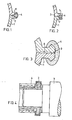
- Fig. 4 Flansch mit Spritzgießabdeckung
- Fig. 5 Flansch mit Spritzgießabdeckung und Zunge
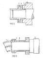
- Fig. 6 Flansch mit verlängerter Spritzgießabdeckung
- Fig. 7 Hohlkörper mit Netzwerk
- In Fig. 1 sind zwei
Schalen 1 überFlansche 2 imStoß 3 durch Spritzgießenerzeugten Kunststoff 4 unter Anschmelzen des Kunststoffes derSchale 1 kraftschlüssig miteinander verbunden, wobei dieser aus einer zweifach abgesetzten Naht besteht. - In Fig. 2 besitzen die
Schalen 1 entlang des Randes je 9 einenFlansch 2, welche untereinander durch einen inAusnehmung 5 durch Spritzgießeneingepreßten Kunststoff 4 verbunden sind. - Fig. 3 zeigt zwei
Schalen 1 mitFlanschen 2, die außen durch Spritzgießen einesKunststoffes 4 klammerartig den wiederhakenartig verbreiterten Rand umfassen. Der Zwischenraum zwischenKunststoff 4 undSchale 1 dient zum Aufbringen der Kräfte durch ein dort angreifendes Werkzeug, wobei die satte Anlage derStöße 3 durch den umlaufenden Nut 6 erleichtert wird. - In Fig. 4 bis 6 ist der durch Kunststoff
umspritzte Flansch 2 derSchale 1 dargestellt, wobei deutlich die verzogene Lage desFlansches 2 vom vorgefertigten Teil zu erkennen ist. In Fig. 5 ist gleichzeitig eineDichtungszunge 7 und in Fig. 6 ein übergangsteil 8 durch Spritzgießen angeformt, welches wiederum einMetallteil 9 aufnimmt. - In Fig. 6 ist ein
Hohlkörper 10 dargestellt, bei dem die Verbindungen derStöße 3 ausKunststoff 4 über einNetzwerk 11 aus gleichem Kunststoff verbunden sind.
- Fig. 1 shell flanges with side injection molding
- Fig. 2 shell flanges with internal injection molding
- Fig. 3 shell flanges with clamp-shaped injection molding
- Fig. 4 flange with injection molding cover
- Fig. 5 flange with injection molding cover and tongue
- Fig. 6 flange with extended injection molding cover
- Fig. 7 hollow body with network
- In Fig. 1, two
shells 1 are connected byflanges 2 in the joint 3 byinjection molding plastic 4 by melting the plastic of theshell 1, this consisting of a double-stepped seam. - In Fig. 2, the
shells 1 along theedge 9 each have aflange 2, which are interconnected by aplastic 4 pressed into therecess 5 by injection molding. - F ig. 3 shows two
shells 1 withflanges 2, which, by injection molding aplastic 4, enclose the barb-like widened edge in a clamp-like manner. The space between the plastic 4 and theshell 1 is used to apply the forces by a tool acting there, the full contact of thejoints 3 being facilitated by the circumferential groove 6. - 4 to 6 shows the
flange 2 of theshell 1 encapsulated by plastic, the distorted position of theflange 2 of the prefabricated part being clearly visible. In Fig. 5, a sealingtongue 7 and in Fig. 6, a transition part 8 is formed by injection molding, which in turn receives ametal part 9. - Strength in F. 6 shows a
hollow body 10 in which the connections of thejoints 3 made ofplastic 4 are connected via anetwork 11 made of the same plastic.
Claims (9)
Applications Claiming Priority (2)
| Application Number | Priority Date | Filing Date | Title |
|---|---|---|---|
| DE3312231 | 1983-04-05 | ||
| DE19833312231 DE3312231A1 (en) | 1983-04-05 | 1983-04-05 | PLASTIC HOLLOW BODIES |
Publications (2)
| Publication Number | Publication Date |
|---|---|
| EP0121207A2 true EP0121207A2 (en) | 1984-10-10 |
| EP0121207A3 EP0121207A3 (en) | 1986-09-17 |
Family
ID=6195507
Family Applications (1)
| Application Number | Title | Priority Date | Filing Date |
|---|---|---|---|
| EP84103307A Withdrawn EP0121207A3 (en) | 1983-04-05 | 1984-03-26 | Hollow plastic body |
Country Status (5)
| Country | Link |
|---|---|
| US (1) | US4544588A (en) |
| EP (1) | EP0121207A3 (en) |
| JP (1) | JPS59198116A (en) |
| CA (1) | CA1214013A (en) |
| DE (1) | DE3312231A1 (en) |
Cited By (9)
| Publication number | Priority date | Publication date | Assignee | Title |
|---|---|---|---|---|
| EP0270864A1 (en) * | 1986-11-15 | 1988-06-15 | Joh, Günter | Intake manifold for an internal-combustion engine |
| EP0333086A2 (en) * | 1988-03-18 | 1989-09-20 | Dario Orsini | Process for injection-molding hollow articles made of polymeric material and items obtained with the process |
| US4911871A (en) * | 1988-08-19 | 1990-03-27 | Eastman Kodak Company | Method for effecting an intraoral dental radiographic film packet improvement |
| WO1992012845A2 (en) * | 1991-01-22 | 1992-08-06 | Rover Group Limited | Fabrication of a composite plastics structure, particularly an internal combustion engine inlet manifold |
| FR2690376A1 (en) * | 1992-04-22 | 1993-10-29 | Aplast Consortium | Plastic hollow parts assembled from two half shells - obtd. by pressure over-moulding along their assembled flanges to form reinforcing channel ensuring consistent mechanical strength |
| WO1995006559A1 (en) * | 1993-09-02 | 1995-03-09 | Filterwerk Mann + Hummel Gmbh | Hollow body, especially intake system in an internal combustion engine |
| EP1941938A1 (en) * | 2006-12-21 | 2008-07-09 | Kyosan Denki Co., Ltd. | Filter device and method for manufacturing the same |
| EP1986539A1 (en) | 2006-02-16 | 2008-11-05 | BSH Bosch und Siemens Hausgeräte GmbH | Dishwasher with spray apparatus |
| WO2022171437A1 (en) * | 2021-02-12 | 2022-08-18 | BSH Hausgeräte GmbH | Fluid-tight component, electrical domestic appliance and method |
Families Citing this family (23)
| Publication number | Priority date | Publication date | Assignee | Title |
|---|---|---|---|---|
| FR2565159B1 (en) * | 1984-05-30 | 1986-10-17 | Aerospatiale | METHOD FOR MANUFACTURING A PART OF A COMPLEX STRUCTURE BY FILAMENTARY WINDING AND A PART ARISING FROM THE PROCESS |
| DE3623418A1 (en) * | 1986-07-11 | 1988-01-28 | Audi Ag | Mechanically loadable joint of construction elements |
| US5283028A (en) * | 1990-05-02 | 1994-02-01 | Penda Corporation | Process for producing a selectively reinforced thermoformed article |
| FR2705578B1 (en) * | 1993-05-25 | 1995-08-18 | Alba Conseil | Tri-material palm with composite blade. |
| US5942169A (en) * | 1994-11-25 | 1999-08-24 | Mitsubishi Engineering-Plastics Corp, | Optimization of overmolding method for three-dimensional hollow molded article |
| DE19501607A1 (en) * | 1995-01-20 | 1996-07-25 | Schaeffler Waelzlager Kg | Locking device with a compensating element |
| IT1295020B1 (en) * | 1997-09-11 | 1999-04-27 | Clam S P A | PROCEDURE FOR THE CREATION OF A SUCTION MUFF, IN PARTICULAR FOR COMPRESSION CIRCUITS FOR REFRIGERATING SYSTEMS |
| DE19918516C2 (en) * | 1999-04-23 | 2003-05-22 | Audi Ag | Method for connecting at least two flat components |
| US6264313B1 (en) | 1999-09-10 | 2001-07-24 | Nypro, Inc. | Fluid delivery manifold and method of manufacturing the same |
| DE10005738A1 (en) * | 2000-02-09 | 2001-08-23 | Trisa Holding Ag Triengen | Hollow toothbrush handle is composed of two shell sections bonded together in an injection mold by an injected seam along the joint between them |
| US6394226B1 (en) | 2000-03-13 | 2002-05-28 | Clam S.P.A. | Method for manufacturing an intake muffler particularly for compression circuit for refrigeration systems and the like |
| JP2001277284A (en) * | 2000-03-31 | 2001-10-09 | Aisin Seiki Co Ltd | Method for molding hollow object consisting of materials of different kind |
| DE10211663B4 (en) * | 2002-03-15 | 2011-02-10 | Johnson Controls Interiors Gmbh & Co. Kg | Method for producing a molded part consisting of two segments integrally connected to one another, in particular for a vehicle interior, and also a molded part produced by this method |
| US20040121109A1 (en) * | 2002-12-20 | 2004-06-24 | Anderson Richard N. | Process for manufacturing composite profiles |
| JP4148023B2 (en) * | 2003-05-22 | 2008-09-10 | 株式会社デンソー | Method for molding hollow molded article and hollow molded article |
| DE102004039132A1 (en) * | 2004-08-11 | 2006-03-02 | Poschmann Industrie-Plastic Gmbh & Co. Kg | Connecting zone between two injection-molded half-shells making up induction manifold comprises interlocking sections of shells which together form transverse cavities and are fixed together by injection molded seals which fill cavities |
| ITMI20062136A1 (en) * | 2006-11-08 | 2008-05-09 | Tecnos Spa | METHOD AND EQUIPMENT FOR THE JOINT OF COVERING ELEMENTS FOR PANEL AND-OR PRINTED PIECES |
| JP5167204B2 (en) * | 2008-07-04 | 2013-03-21 | 大成プラス株式会社 | Bonded sheet metal structure |
| JP5453061B2 (en) * | 2009-11-11 | 2014-03-26 | タイガースポリマー株式会社 | Ventilation duct |
| CN102529093A (en) * | 2010-12-29 | 2012-07-04 | 瑞虹精密工业股份有限公司 | Method for combining plastic to metal substrate |
| JP6734720B2 (en) * | 2016-07-15 | 2020-08-05 | 日本サーモスタット株式会社 | Resin molded product and manufacturing method thereof |
| FR3067280B1 (en) * | 2017-06-09 | 2019-07-19 | Novares France | METHOD FOR MANUFACTURING AN AIR INTAKE DUCT |
| DE102019211022A1 (en) * | 2019-07-25 | 2021-01-28 | Henkel Ag & Co. Kgaa | Arrangement of thermoplastic components |
Citations (10)
| Publication number | Priority date | Publication date | Assignee | Title |
|---|---|---|---|---|
| FR1112984A (en) * | 1954-10-22 | 1956-03-21 | Surface coating manufacturing process | |
| FR1145349A (en) * | 1955-01-15 | 1957-10-24 | Non-expandable plastic container | |
| FR69373E (en) * | 1955-08-05 | 1958-11-06 | Process and machine for ribbing or welding plastic sheets and applications to packaging and tanks | |
| FR1233620A (en) * | 1959-04-28 | 1960-10-12 | Watertight container in thermoplastic material, composed of multiple elements assembled by overmolded connection belts | |
| FR2173851A1 (en) * | 1972-03-02 | 1973-10-12 | Fukuoka Tatsuo | Shoes or handbags etc - with a thermoplastic base moulded to similar or different material parts |
| DE2501291A1 (en) * | 1975-01-15 | 1976-07-22 | Roehm Gmbh | Injection moulding of hollow bodies - using three-part injection mould |
| FR2381618A1 (en) * | 1977-02-24 | 1978-09-22 | Ouest Cie | METHOD OF MANUFACTURING A FLEXIBLE SAFETY TANK FOR HYDROCARBONS, ESPECIALLY FOR INDUSTRIAL VEHICLES |
| US4261947A (en) * | 1975-05-12 | 1981-04-14 | Yoshio Ogi | Method for manufacturing hollow plastic articles by joining hollow molded portions by a molded joint |
| FR2486196A1 (en) * | 1980-07-01 | 1982-01-08 | Valeo | BENDED TUBING, ESPECIALLY FOR CONNECTING A HEAT EXCHANGER TO A CIRCUIT |
| US4347208A (en) * | 1981-04-13 | 1982-08-31 | Amf Incorporated | Method of making filter cell having sealed periphery |
Family Cites Families (6)
| Publication number | Priority date | Publication date | Assignee | Title |
|---|---|---|---|---|
| US4074961A (en) * | 1972-03-02 | 1978-02-21 | Altstadter Verpackungs-Vertriebs Gmbh | Apparatus for producing containers |
| US3893777A (en) * | 1974-07-31 | 1975-07-08 | Wilson M Jones | Structural joint |
| US4038358A (en) * | 1975-11-25 | 1977-07-26 | Wrasman Thomas J | Method of making a valve |
| US4263237A (en) * | 1976-05-10 | 1981-04-21 | Weeden Frank G | Method of making expandable member for forming seals and applying force |
| US4404053A (en) * | 1980-02-19 | 1983-09-13 | Victor Saffire | Method of making a javelin |
| US4447373A (en) * | 1982-02-16 | 1984-05-08 | The Procter & Gamble Company | Process for making filled articles from polymeric material |
-
1983
- 1983-04-05 DE DE19833312231 patent/DE3312231A1/en not_active Ceased
-
1984
- 1984-03-26 US US06/593,279 patent/US4544588A/en not_active Expired - Fee Related
- 1984-03-26 EP EP84103307A patent/EP0121207A3/en not_active Withdrawn
- 1984-04-02 JP JP59063440A patent/JPS59198116A/en active Pending
- 1984-04-03 CA CA000451165A patent/CA1214013A/en not_active Expired
Patent Citations (10)
| Publication number | Priority date | Publication date | Assignee | Title |
|---|---|---|---|---|
| FR1112984A (en) * | 1954-10-22 | 1956-03-21 | Surface coating manufacturing process | |
| FR1145349A (en) * | 1955-01-15 | 1957-10-24 | Non-expandable plastic container | |
| FR69373E (en) * | 1955-08-05 | 1958-11-06 | Process and machine for ribbing or welding plastic sheets and applications to packaging and tanks | |
| FR1233620A (en) * | 1959-04-28 | 1960-10-12 | Watertight container in thermoplastic material, composed of multiple elements assembled by overmolded connection belts | |
| FR2173851A1 (en) * | 1972-03-02 | 1973-10-12 | Fukuoka Tatsuo | Shoes or handbags etc - with a thermoplastic base moulded to similar or different material parts |
| DE2501291A1 (en) * | 1975-01-15 | 1976-07-22 | Roehm Gmbh | Injection moulding of hollow bodies - using three-part injection mould |
| US4261947A (en) * | 1975-05-12 | 1981-04-14 | Yoshio Ogi | Method for manufacturing hollow plastic articles by joining hollow molded portions by a molded joint |
| FR2381618A1 (en) * | 1977-02-24 | 1978-09-22 | Ouest Cie | METHOD OF MANUFACTURING A FLEXIBLE SAFETY TANK FOR HYDROCARBONS, ESPECIALLY FOR INDUSTRIAL VEHICLES |
| FR2486196A1 (en) * | 1980-07-01 | 1982-01-08 | Valeo | BENDED TUBING, ESPECIALLY FOR CONNECTING A HEAT EXCHANGER TO A CIRCUIT |
| US4347208A (en) * | 1981-04-13 | 1982-08-31 | Amf Incorporated | Method of making filter cell having sealed periphery |
Non-Patent Citations (1)
| Title |
|---|
| PATENTS ABSTRACTS OF JAPAN, Band 4, Nr. 164 (M-41) [646], 14. November 1980, Seite 85 M 41; & JP - A - 55 113 541 (NIPPON SEIKOSHO K.K.) 02.09.1980 * |
Cited By (14)
| Publication number | Priority date | Publication date | Assignee | Title |
|---|---|---|---|---|
| EP0270864A1 (en) * | 1986-11-15 | 1988-06-15 | Joh, Günter | Intake manifold for an internal-combustion engine |
| EP0333086A2 (en) * | 1988-03-18 | 1989-09-20 | Dario Orsini | Process for injection-molding hollow articles made of polymeric material and items obtained with the process |
| EP0333086A3 (en) * | 1988-03-18 | 1991-08-28 | Dario Orsini | Process for injection-molding hollow articles made of polymeric material and items obtained with the process |
| US4911871A (en) * | 1988-08-19 | 1990-03-27 | Eastman Kodak Company | Method for effecting an intraoral dental radiographic film packet improvement |
| GB2268117B (en) * | 1991-01-22 | 1995-06-07 | Rover Group | Fabrication of a composite plastics structure,particularly an internal combustion engine inlet manifold |
| WO1992012845A3 (en) * | 1991-01-22 | 1992-09-17 | Rover Group | Fabrication of a composite plastics structure, particularly an internal combustion engine inlet manifold |
| GB2268117A (en) * | 1991-01-22 | 1994-01-05 | Rover Group | Fabrication of a composite plastics structure,particularly an internal combustion engine inlet manifold |
| WO1992012845A2 (en) * | 1991-01-22 | 1992-08-06 | Rover Group Limited | Fabrication of a composite plastics structure, particularly an internal combustion engine inlet manifold |
| FR2690376A1 (en) * | 1992-04-22 | 1993-10-29 | Aplast Consortium | Plastic hollow parts assembled from two half shells - obtd. by pressure over-moulding along their assembled flanges to form reinforcing channel ensuring consistent mechanical strength |
| WO1995006559A1 (en) * | 1993-09-02 | 1995-03-09 | Filterwerk Mann + Hummel Gmbh | Hollow body, especially intake system in an internal combustion engine |
| EP1986539A1 (en) | 2006-02-16 | 2008-11-05 | BSH Bosch und Siemens Hausgeräte GmbH | Dishwasher with spray apparatus |
| EP1986539B1 (en) * | 2006-02-16 | 2016-03-09 | BSH Hausgeräte GmbH | Dishwasher with spray apparatus |
| EP1941938A1 (en) * | 2006-12-21 | 2008-07-09 | Kyosan Denki Co., Ltd. | Filter device and method for manufacturing the same |
| WO2022171437A1 (en) * | 2021-02-12 | 2022-08-18 | BSH Hausgeräte GmbH | Fluid-tight component, electrical domestic appliance and method |
Also Published As
| Publication number | Publication date |
|---|---|
| JPS59198116A (en) | 1984-11-09 |
| CA1214013A (en) | 1986-11-18 |
| DE3312231A1 (en) | 1984-10-11 |
| EP0121207A3 (en) | 1986-09-17 |
| US4544588A (en) | 1985-10-01 |
Similar Documents
| Publication | Publication Date | Title |
|---|---|---|
| EP0121207A2 (en) | Hollow plastic body | |
| DE10314209B3 (en) | Housing for a radial compressor and method for producing the housing | |
| DE4441219C2 (en) | Pendulum support for the insertion of bearing strokes forming the bearing points for the articulated connection of chassis parts in motor vehicles | |
| DE10153314B4 (en) | Resin intake manifold and process for its manufacture | |
| DE2627346A1 (en) | METHOD OF MANUFACTURING PLASTIC ARTICLES WITH SLIDING PARTS | |
| DE102004032362A1 (en) | Method for producing a composite component and composite component | |
| EP0158046B1 (en) | Connection of two parts, particularly of two plastics material half shells | |
| DE2928582C2 (en) | Reflector for motor vehicle headlights and method for its manufacture | |
| WO2019223935A1 (en) | Node element for a vehicle body, vehicle body, vehicle, and method for producing a node element | |
| WO2018145810A1 (en) | Sealing element comprising a cover strip | |
| DE3613191C2 (en) | ||
| DE4241409C2 (en) | Method and device for producing a component by injection molding at least two plastic elements and by joining these elements together after injection molding | |
| EP3412505B1 (en) | Method for producing a light component with spacer, correspondingly manufactured light component, and a vehicle lamp fitting with such a light component | |
| EP0966345B1 (en) | Process for manufacturing hollow plastic objects | |
| DE10014336A1 (en) | Bearing or steering rack has a main body casting covered with a plastic skin | |
| EP2457808A1 (en) | Method for manufacturing a side wall | |
| EP3771506B1 (en) | Casting method with a shaping contour for producing a core, component and system for producing a component | |
| DE102015014357B4 (en) | Method for producing a node structure for a vehicle body | |
| DE4305196C2 (en) | Process for producing an injection mold | |
| DE69611865T2 (en) | Process for producing an article from plastic by blow molding | |
| EP0950503B1 (en) | Method for making thermoplastic hollow bodies | |
| DE3815616A1 (en) | METHOD AND MOLDING TOOL FOR PRODUCING MOLDED PARTS FROM A LIQUID REACTION MIXTURE | |
| DE19615309A1 (en) | Injection moulding and joining of objects formed by two separate sections | |
| DE2553062A1 (en) | ENGINE BLOCK AND PROCESS FOR ITS MANUFACTURING | |
| DE102022105648B3 (en) | Method for producing a plastic component with a carrier part and a cover layer applied thereto and plastic component produced according to the method |
Legal Events
| Date | Code | Title | Description |
|---|---|---|---|
| PUAI | Public reference made under article 153(3) epc to a published international application that has entered the european phase |
Free format text: ORIGINAL CODE: 0009012 |
|
| 17P | Request for examination filed |
Effective date: 19840326 |
|
| AK | Designated contracting states |
Designated state(s): DE FR GB IT |
|
| PUAL | Search report despatched |
Free format text: ORIGINAL CODE: 0009013 |
|
| AK | Designated contracting states |
Kind code of ref document: A3 Designated state(s): DE FR GB IT |
|
| 17Q | First examination report despatched |
Effective date: 19870430 |
|
| STAA | Information on the status of an ep patent application or granted ep patent |
Free format text: STATUS: THE APPLICATION HAS BEEN WITHDRAWN |
|
| 18W | Application withdrawn |
Withdrawal date: 19871105 |
|
| RIN1 | Information on inventor provided before grant (corrected) |
Inventor name: SCHAUF, DIETER, ING. GRAD. |