EP0119366A1 - Toilet device having a hydraulic valve incorporated in the last part of the siphon - Google Patents
Toilet device having a hydraulic valve incorporated in the last part of the siphon Download PDFInfo
- Publication number
- EP0119366A1 EP0119366A1 EP83430030A EP83430030A EP0119366A1 EP 0119366 A1 EP0119366 A1 EP 0119366A1 EP 83430030 A EP83430030 A EP 83430030A EP 83430030 A EP83430030 A EP 83430030A EP 0119366 A1 EP0119366 A1 EP 0119366A1
- Authority
- EP
- European Patent Office
- Prior art keywords
- valve
- siphon
- rod
- jack
- bowl
- Prior art date
- Legal status (The legal status is an assumption and is not a legal conclusion. Google has not performed a legal analysis and makes no representation as to the accuracy of the status listed.)
- Withdrawn
Links
Images
Classifications
-
- E—FIXED CONSTRUCTIONS
- E03—WATER SUPPLY; SEWERAGE
- E03D—WATER-CLOSETS OR URINALS WITH FLUSHING DEVICES; FLUSHING VALVES THEREFOR
- E03D5/00—Special constructions of flushing devices, e.g. closed flushing system
- E03D5/012—Special constructions of flushing devices, e.g. closed flushing system combined with movable closure elements in the bowl outlet
Definitions
- a particular device allows the evacuation of the air inside the siphon during filling thereof and ensures the non-reintroduction of air throughout the duration of the siphonic suction.
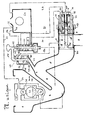
- the bowl (I) extends downwards through the orifice (2) and a conduit (3) forming a siphon, with its culminating part (4), its descending branch (5) and the terminal part (6) which communicates with the downpipe (7).
- a valve (8) furnished with a peripheral seal (9) slides inside (6) to alternate between closed and open positions. Its travel is arranged so that at the start of its opening, the sliding takes place on a solid cylindrical part (6a).
- This valve (8) is, by a rod (IO), integral with a piston (II) sliding itself in a jack (12) constituted by an envelope (I3), a rear flange (14) and a front flange (I5).
- a rod (IO) integral with a piston (II) sliding itself in a jack (12) constituted by an envelope (I3), a rear flange (14) and a front flange (I5).
- This valve also comprises, on the jack side, a cylindrical tube (16) of the same diameter as it, the assembly being intended to slide inside the sheath (6), the extension on the jack side comprises a housed seal (17).
- the rod (10) has an internal recess (18).
- the piston (II) comprises, in addition to its peripheral seal (I9), a housed seal (20).
- the rear flange (14) has an orifice (2I) which is that of the water inlet actuating the closing of the valve.
- This flange (14) further carries in its center a fixed cylindrical tube (22) which penetrates inside the cylinder body (12) in the axis of sliding thereof and extends outside of the flange (14) by the conduit (23) which supplies the reservoir (24).
- the outside diameter of the tube (22) is arranged so as to slide in the recess (18), the seal (20) ensuring the The length of the tube (22) inside the cylinder body is established so that, in the end position corresponding to the complete closure of the valve, the piston (II) escapes of the tubing by providing a space (25) between the internal face (26) of the piston and the end (27) of the tubing (22).
- the actuator-valve assembly is hydraulically actuated by the piston distributor (28) and by means of its control rod (29).
- the conduits (30) and (31) starting from the distributor (28) to open into the body of the cylinder (I2) match respectively to the opening and closing circuits of the valve.
- the reservoir (24) the function of which is to store the water intended to reconstitute the water guard, is also of known type. It carries, in its upper part, an orifice (32) extending outwards by a conduit (33) which, parl'o rifice (34), feeds a ball box (35).
- This ball box (35) has, compared to those of the type. known, the originality of comprising in its middle part, a cage (36) inside which is placed a determined volume such as for example a sphere of very low density which is thus interposed between the upper light ball (38) and the lower heavy ball (39).
- the inside of the box is arranged to allow the free circulation of water.
- the sphere (37) is, in its upper part, in contact with the lower part of the ball (38).
- the level (40) corresponds to that of the natural floating of the sphere (37). We understand that, when this level rises, for example up to (40 a), the sphere (37) lifts and lifts in turn the ball (3 ⁇ ) which, by placing itself in the path of the jet, causes the balls to block on their respective sealing seats.
- the injection can be interrupted at the desired level.
- the reservoir (24) also has at its upper part another orifice (41) extending towards the outside by a conduit (42) opening into the upper part of the control distributor (28).
- the figure also shows in detail the particular device relating to the emptying of air into the siphon.
- An orifice (43) placed at the highest point (4) of the siphon communicates with a conduit (44) in ascending slope which opens, through the orifice (45) in the lower flange of a housing (46) which has a cover. upper (47) in which is arranged a bore (48) comprising a seal (49) for example O-ring.
- the housing (46) provides, in its internal part, a compartment (50) large enough to allow the free passage of air, inside which moves a rod (51) which slides in the bore (48 ) and carries, at its lower part, a valve (52) provided with a seal, for example made of rubber.
- the axis of the rod (51), placed in a substantially vertical position, corresponds to the axis of the orifice (45) so that the sliding of the rod (51) causes, alternately, through the valve (52), the opening and closing of the orifice (45).
- an orifice (53) extending outwardly by the con duct (54) which is in a downward slope and opens into the downward sheath.
- the rod (51) is extended outside the bore (48) by a rod (55) which is itself integral with the rod (29) for controlling the distributor (28), the assembly being arranged so that the rods (51) and (29) are parallel.
- the arrangement of the various elements with respect to each other is organized so that the level (40 a) is placed below that of the orifice (53) so that there can be no flow of liquid capable of interfere with the operation of the appliance.
- the water circulates through the orifice (32) and the conduit (33) towards the orifice (34) through which it enters the ball box (35). sprinkles the bowl which raises the level both in the bowl and in the siphon.
- valve (52) is placed on its seat of the orifice (45) preventing any possibility of rein air in the siphon.
- the valve opens causing a powerful siphonic suction which evacuates the effluents.
- the tubing (16) acts, during the entire closing phase of the valve ( ⁇ ) and sliding opening as a protective sheath preventing any possibility of contact between the polluted liquid located in front of the valve (8) and the rod ( No pollution can thus go back to the distributor and the water distribution network.
- This end portion (6) could for example be inclined downward in a position substantially parallel to the rising branch of the siphon.
- the terminal part of the siphon in which the valve slides is arranged horizontally and that its axis is perpendicular to the longitudinal median plane of the device.
- This arrangement offers the advantage, by a telescopic fitting of the sheath (6) on the end of the siphon, to be able to adjust by simple pivoting, the position of the descent sheath (7) so as to respond, with a single model of bowl, to all possible connection situations.
Abstract
Description
Dans les appareils de W.C. à aspiration siphonique de type traditionnel, l'eau du réservoir de chasse,brusquement introduite dans la cuvette,provoque une montée en niveau à l'intérieur de celle ci du fait que le faible diamètre du tuyau constituant le siphon n'absorbe pas le débit d'alimentation. Ainsi le siphon se remplit du liquide qui chasse l'air devant lui et lorsque le siphon est plein,l'aspiration siphonique se déclanche.Pendant cette phase,la plus grande partie de l'eau du réservoir s'est écoulée dans la descente en vertu du principe des vases communicants,d'où il résulte une consommation d'eau importante.La présente invention a pour objet de remédier à cet inconvénient en réduisant considérablement cette consommation.In traditional type siphonic suction WCs, the water from the flushing tank, suddenly introduced into the bowl, causes a level rise inside the latter because the small diameter of the pipe constituting the siphon n '' does not absorb the feed rate. Thus the siphon fills with the liquid which expels the air in front of it and when the siphon is full, the siphonic suction is triggered. During this phase, most of the water in the tank has flowed into the descent by virtue of the principle of communicating vessels, which results in a significant consumption of water. The present invention aims to remedy this drawback by considerably reducing this consumption.
Elle est caractérisée par le fait qu'après remplissage du siphon,un clapet hydraulique incorporé dans sa partie termina. le coulisse de manière étanche tout d'abord dans une partie cylindrique pleine afin d'agir à la manière d'une pompe aspi- rantepuis,en libérant l'orifice de la gaine de descente et en la mettant ainsi en communication directe avec le siphon,provoque une aspiration siphonique de grande puissance.It is characterized by the fact that after filling the siphon, a hydraulic valve incorporated in its finished part. the slide in a sealed manner first in a full cylindrical part in order to act in the manner of a suction pump since then, freeing the orifice of the downpipe and thus putting it in direct communication with the siphon , causes a siphonic suction of great power.
Un dispositif particulier permet l'évacuation de l'air à l' intérieur du siphon pendant le remplissage de celui-ci et assure la non réintroduction d'air pendant toute la durée de l' aspiration siphonique.A particular device allows the evacuation of the air inside the siphon during filling thereof and ensures the non-reintroduction of air throughout the duration of the siphonic suction.
Le cycle automatique correspondant à une chasse comprend cinq phases successives à savoir:
- a) Fermeture du clapet qui,en position de non usage,reste ouvert.
- b) Remplissage d'un petit réservoir auxiliaire de type connu.
- c)Arrosage de la cuvette avec,simultanément,montée en niveau et remplissage du siphon.
- d) Ouverture du clapet avec évacuation des effluents par aspiration siphonique.
- e) Vidange du réservoir auxiliaire dans le fond de la cuvette de manière à y rétablir la garde d'eau à son niveau convenable.
- a) Closing of the valve which, in the non-use position, remains open.
- b) Filling a small auxiliary tank of known type.
- c) Watering the bowl with, simultaneously, leveling and filling the siphon.
- d) Opening of the valve with evacuation of effluents by siphonic suction.
- e) Emptying the auxiliary tank into the bottom of the bowl so as to restore the water level to its proper level.
Des variantes sont possibles à propos du réservoir dont le remplissage peut s'effectuer à d'autres moments du cycle, notam ment avant la fermeture du clapet.Variants are possible with regard to the reservoir, the filling of which can take place at other times of the cycle, in particular before the valve is closed.
T'invention sera mieux comprise si on se réfère à la figure annexée dans laquelle la cuvette (I) se prolonge vers le bas par l'orifice (2) et un conduit (3) formant siphon,avec sa partie culminante (4),sa branche descendante (5) et la partie terminale (6) qui communique avec la gaine de descente (7).The invention will be better understood if we refer to the figure annexed in which the bowl (I) extends downwards through the orifice (2) and a conduit (3) forming a siphon, with its culminating part (4), its descending branch (5) and the terminal part (6) which communicates with the downpipe (7).
Un clapet (8) garni d'un joint d'étanchéïté périphérique (9) coulisse à l'intérieur de (6) pour se metttre alternativement en position de fermeture et d'ouverture. Sa course est aménagée de manière à ce qu'au début de son ouverture,le coulissement s'effectue sur une partie cylindrique pleine (6 a).A valve (8) furnished with a peripheral seal (9) slides inside (6) to alternate between closed and open positions. Its travel is arranged so that at the start of its opening, the sliding takes place on a solid cylindrical part (6a).
Ce clapet (8) est,par une tige (IO),solidaire d'un piston (II) coulissant lui-même dans un vérin (12) constitué par une enveloppe (I3),une flasque arrière (14) et une flasque avant (I5).This valve (8) is, by a rod (IO), integral with a piston (II) sliding itself in a jack (12) constituted by an envelope (I3), a rear flange (14) and a front flange (I5).
Ce clapet comporte encore,côté vérin,une tubulure cylindrique (16) de même diamètre que lui, l'ensemble étant destiné à coulisser à l'intérieur de la gaine (6) dont le prolongement côté vérin comporte un joint logé (17).This valve also comprises, on the jack side, a cylindrical tube (16) of the same diameter as it, the assembly being intended to slide inside the sheath (6), the extension on the jack side comprises a housed seal (17).
La tige (10) comporte un évidement intérieur (18).Le piston (II) comporte, outre son joint d'étanchéité périphérique (I9),un joint logé (20).The rod (10) has an internal recess (18). The piston (II) comprises, in addition to its peripheral seal (I9), a housed seal (20).
La flasque arrière (14) comporte un orifice (2I) qui est celui de l'arrivée de l'eau actionnant la fermeture du clapet.The rear flange (14) has an orifice (2I) which is that of the water inlet actuating the closing of the valve.
Cette flasque (14) porte en outre en son centre une tubulure cylindrique fixe (22) qui pénètre à l'intérieur du corps du vérin (12) dans l'axe de coulissement de celui-ci et se prolonge,à l'extérieur de la flasque (14) par le condut (23) qui alimente le réservoir (24).Le diamètre extérieur de la tubulure (22) est ménagé de manière à coulisser dans l'évidement (18), le joint (20) assurant l'étanchéité tout le long du coulissement.La longueur de la tubulure (22) à l'intérieurdu corps de vérin est établie de manière à ce que,en position de fin de course correspondant à la fermeture complète du clapet, le piston (II) échappe de la tubulure en ménageant un espace (25) entre la face interne (26) du piston et l'extrémité (27) de la tubulure (22).This flange (14) further carries in its center a fixed cylindrical tube (22) which penetrates inside the cylinder body (12) in the axis of sliding thereof and extends outside of the flange (14) by the conduit (23) which supplies the reservoir (24). The outside diameter of the tube (22) is arranged so as to slide in the recess (18), the seal (20) ensuring the The length of the tube (22) inside the cylinder body is established so that, in the end position corresponding to the complete closure of the valve, the piston (II) escapes of the tubing by providing a space (25) between the internal face (26) of the piston and the end (27) of the tubing (22).
L'ensemble vérin-clapet est actionné hydrauliquement par le distributeur (28)à pistons et au moyen de sa tige de commande (29).Les conduits (30) et (31) partant du distributeur (28) pour déboucher dans le corps du vérin (I2)correspondent respectivement aux circuits d'ouverture et de fermeture du clapet.The actuator-valve assembly is hydraulically actuated by the piston distributor (28) and by means of its control rod (29). The conduits (30) and (31) starting from the distributor (28) to open into the body of the cylinder (I2) match respectively to the opening and closing circuits of the valve.
Le distributeur proprement dit ainsi que sa liaison fonctionnelle avec le vérin et le réservoir sont de types connus la nouveauté résidant ici dans le fait que,en position de non usage:
- a) Le clapet (o) reste ouvert ce qui présente l'avantage qu' en cas de coupure d'eau,il est possible d'utiliser l'appareil en y versant de l'eau préalablement stockée.
- b) L'enclanchement d'un cycle se réalise par soulèvement de la tige (29) de commande qui est abaissée en position de non usage ce qui présente l'avantage de rendre moins praticable la manoeuvre qui consiste à s'opposer au fonction nement normal de l'appareil.
- a) The valve (o) remains open, which has the advantage that in the event of a water cut, it is possible to use the device by pouring water previously stored in it.
- b) The engagement of a cycle is carried out by lifting the control rod (29) which is lowered into the non-use position, which has the advantage of making the operation which consists in opposing the operation less practical. normal of the device.
Le réservoir (24) dont la fonction est d'emmagasiner l'eau destinée à reconstituer la garde d'eau est également de type connu.Il porte,dans sa partie supérieure,un orifice (32) se prolongeant vers l'extérieur par un conduit (33) qui,parl'o rifice (34),alimente une boite à billes (35).The reservoir (24), the function of which is to store the water intended to reconstitute the water guard, is also of known type. It carries, in its upper part, an orifice (32) extending outwards by a conduit (33) which, parl'o rifice (34), feeds a ball box (35).
Cette boite à billes (35) présente,par rapport à celles de type. connu,l'originalité de comporter dans sa partie médiane,une cage (36) à l'intérieur de laquelle est placé un volume déterminé comme par exemple une sphère de très faible densité qui se trouve ainsi intercalée entre la bille légère supérieure (38) et la bille pesante inférieure (39).This ball box (35) has, compared to those of the type. known, the originality of comprising in its middle part, a cage (36) inside which is placed a determined volume such as for example a sphere of very low density which is thus interposed between the upper light ball (38) and the lower heavy ball (39).
L'intérieur de la boite est ménagé pour permettre la libre circulation de l'eau.La sphère (37) est,dans sa partie supérieure,en contact avec la partie inférieure de la bille (38). Le niveau (40) correspond à celui de la flotaison naturelle de la sphère (37).On comprend que,lorsque ce niveau monte,par exemple jusqu'en (40 a),la sphère (37) se soulève et soulève à son tour la bille (3υ) qui,en se plaçant dans la trajectoire du jet,provoque le blocage des billes sur leur siège d'étanché ité respectifs.The inside of the box is arranged to allow the free circulation of water. The sphere (37) is, in its upper part, in contact with the lower part of the ball (38). The level (40) corresponds to that of the natural floating of the sphere (37). We understand that, when this level rises, for example up to (40 a), the sphere (37) lifts and lifts in turn the ball (3υ) which, by placing itself in the path of the jet, causes the balls to block on their respective sealing seats.
Par cette disposition,on obtient que le blocage des billes s'effectue alors que le niveau atteint par le liquide dans la cuvette est sensiblement en dessous de celui de l'injection de l'eau dans la cuvette.Ceci peut être avantageux pour améliorer le fonctionnement de l'appareil,réduire la consommation d'eau tout en assurant un arrosage maximum de la cuvette.By this arrangement, it is obtained that the blocking of the balls takes place while the level reached by the liquid in the bowl is substantially below that of the injection of water into the bowl. This may be advantageous for improving the operation of the device, reduce water consumption while ensuring maximum watering of the bowl.
En choisissant un volume intermédiaire de hauteur appro prié,on peut obtenir l'interruption de l'injection au niveau désiré.By choosing an appropriate intermediate height volume, the injection can be interrupted at the desired level.
Le réservoir (24) comporte encore à sa partie supérieure un autre orifice (41) se prolongeant vers l'extérieur par un conduit (42) débouchant dans la partie supérieure du distributeur de commande (28).The reservoir (24) also has at its upper part another orifice (41) extending towards the outside by a conduit (42) opening into the upper part of the control distributor (28).
La figure lontre aussi dans le détail le dispositif particulier relatif au vidage de l'air dans le siphon.The figure also shows in detail the particular device relating to the emptying of air into the siphon.
Un orifice (43) placé à la partie culminante (4) du siphon communique avec un conduit (44) en pente ascendante qui débouche,par l'orifice (45) dans la flasque inférieure d'un boitier (46) qui comporte un couvercle supérieur (47) dans lequel est aménagé un alésage (48) comportant un joint d'étanchéité (49) par exemple torique.An orifice (43) placed at the highest point (4) of the siphon communicates with a conduit (44) in ascending slope which opens, through the orifice (45) in the lower flange of a housing (46) which has a cover. upper (47) in which is arranged a bore (48) comprising a seal (49) for example O-ring.
Le boitier (46) ménage,dans sa partie interne,un compartiment (50) assez largement dimensionné pour permettre le libre passage de l'air,à l'intérieur duquel se déplace une tige (51) qui coulisse dans l'alésage (48) et porte,à sa partie inférieure,un clapet (52) muni d'une garniture d'étanchéité, par exemple en cahoutchouc.The housing (46) provides, in its internal part, a compartment (50) large enough to allow the free passage of air, inside which moves a rod (51) which slides in the bore (48 ) and carries, at its lower part, a valve (52) provided with a seal, for example made of rubber.
L'axe de la tige (51),placé en position sensiblement verticale,correspond à l'axe de l'orifice (45) de manière à ce que le coulissement de la tige (51) provoque, alternativement, par l'intermédiaire du clapet (52),l'ouverture et la fermeture de l'orifice (45).The axis of the rod (51), placed in a substantially vertical position, corresponds to the axis of the orifice (45) so that the sliding of the rod (51) causes, alternately, through the valve (52), the opening and closing of the orifice (45).
Dans la partie supérieure du compartiment (50) est ménagé un orifice (53) se prolongeant vers l'extérieur par le con duit (54) qui est en pente descendante et débouche dans la gaine de descente.In the upper part of the compartment (50) is an orifice (53) extending outwardly by the con duct (54) which is in a downward slope and opens into the downward sheath.
La tige (51) se prolonge à l'extérieur de l'alésage (48) par une tige (55) elle même solidaire de la tige (29) de commande du distributeur (28),l'ensemble étant aménagé de telle sorte que les tiges (51) et (29) soient parallèles.The rod (51) is extended outside the bore (48) by a rod (55) which is itself integral with the rod (29) for controlling the distributor (28), the assembly being arranged so that the rods (51) and (29) are parallel.
La disposition des différents éléments les uns par rapport aux autres est organisée de manière à ce que le niveau (40 a) soit placé en dessous de celui de l'orifice (53) afin qu'il ne puisse y avoir aucun écoulement de liquide susceptible de gêner le fonctionnenent de l'appareil.The arrangement of the various elements with respect to each other is organized so that the level (40 a) is placed below that of the orifice (53) so that there can be no flow of liquid capable of interfere with the operation of the appliance.
On peut maintenant,à l'aide de la figure,voir le fonctionnement de l'appareil:
- L'enclanchement d'un cycle est obtenu par le soulèvement manuel de la tige (29) ce qui amène les pistons du distributeur dans la position figurée en pointillé.Le conduit (3I) est alors alimenté et la pression de l'eau pousse le piston (II) de la position figurée en traits pleins vers celle figurée en pointillé du fait que les joints (19) et (20) empêchent toute communication entre les compartiments placés de part et d'autre de ce piston (II) à l'intérieur du corps de vérin et ceci pendant toute la durée du coulissement,l'échappement s'effectuant par le conduit (30).
- The engagement of a cycle is obtained by manual lifting of the rod (29) which brings the distributor pistons into the position shown in dotted lines. The duct (3I) is then supplied and the water pressure pushes the piston (II) from the position shown in solid lines to that shown in dotted lines because the seals (19) and (20) prevent any communication between the compartments placed on either side of this piston (II) at the inside the cylinder body and this for the entire duration of the sliding, the exhaust being effected by the conduit (30).
On voit que le clapet étant parvenu à sa position de fermeture,l'eau continue d'arriver par (2I) et s'introduit par l'espace (25) dans la tubulure (22) et,par le conduit (23) va alimenter le réservoir (24) sans qu'il y ait eu déplacement de la tige (29) de sorte que le circuit de fermeture devient circuit d'arrosage.We see that the valve having reached its closed position, the water continues to arrive by (2I) and is introduced through the space (25) in the tubing (22) and, through the conduit (23) goes supply the reservoir (24) without displacement of the rod (29) so that the closing circuit becomes a sprinkling circuit.
En effet,après avoir rempli le réservoir (24),1'eau circule par l'orifice (32) et le conduit (33) vers l'orifice (34) par lequel elle pénètre dans la boite à billes (35).Elle arrose la cuvette ce qui fait monter le niveau à la fois dans la cuvette et dans le siphon.In fact, after filling the reservoir (24), the water circulates through the orifice (32) and the conduit (33) towards the orifice (34) through which it enters the ball box (35). sprinkles the bowl which raises the level both in the bowl and in the siphon.
Du fait que la tige (51),solidaire de la tige (29) a été soulevée lors de l'enclanchement du cycle et avec elle le clapet (52) qui lui est solidaire également,ce clapet (52) vient se placer dans la position (52 a).L'air se trouvant dans la partie culminante (4) du siphon peut s'évacuer par l'orifice (43),le conduit (44),le compartiment (50),l'orifice (53) et le conduit (54) vers la gaine de descente.Because the rod (51), integral with the rod (29) was raised when the cycle was engaged and with it the valve (52) which is also integral with it, this valve (52) is placed in the position (52 a). The air in the culminating part (4) of the siphon can escape through the orifice (43), the duct (44), the compartment (50), the orifice (53) and the conduit (54) to the downcomer.
Le blocage des billes dans la boite (35) au niveau (40 a) correspondant au remplissage total du siphon,provoque la mon- tée en pression dans tout le circuit fermeture-arrosage.Par le conduit (42) cette pression s'applique sur le piston supérieur de la tige de commande (29) du distributeur pour provoquer le coulissement de:.la tige (29) vers le bas.Le distributeur de commande se trouve ainsi ramené à sa position initiale qui est celle correspondant à l'ouverture du clapet (8) figurée en traits pleins.Blocking the balls in the box (35) at (40) corresponding to complete filling of the siphon causes my - ted in pressure throughout the arrosage.Par closure system conduit (42) that pressure is applied to the upper piston of the control rod (29) of the distributor to cause the sliding of: .the rod (29) downwards. The control distributor is thus returned to its initial position which is that corresponding to the opening of the valve (8) shown in solid lines.
Simultanément le clapet (52) vient se placer sur son siège de l'orifice (45) empêchant toute possibilité de réintroduction d'air dans le siphon.Le clapet s'ouvre en provoquant une puissante aspiration siphonique qui assure l'évacuation des effluents.Simultaneously the valve (52) is placed on its seat of the orifice (45) preventing any possibility of rein air in the siphon. The valve opens causing a powerful siphonic suction which evacuates the effluents.
Dans cette position la pression à zéro dans l'ensemble du circuit fermeture-arrosage de sorte que le réservoir(24) et la boite à billes (35) se vidangent dans la cuvette.In this position the pressure at zero in the entire closing-sprinkling circuit so that the reservoir (24) and the ball box (35) drain into the bowl.
La tubulure (16) agit,pendant toute la phase de fermeture du clapet (δ) et de coulissement d'ouverture comme une gaine protectrice empêchant toute possibilité de contact entre le liquide pollué se trouvant en avant du clapet (8) et la tige (10).Aucune pollution ne pourra ainsi remonter jusqu' au distributeur et au réseau de distribution de l'eau.The tubing (16) acts, during the entire closing phase of the valve (δ) and sliding opening as a protective sheath preventing any possibility of contact between the polluted liquid located in front of the valve (8) and the rod ( No pollution can thus go back to the distributor and the water distribution network.
La description qui vient d'être faite se rapporte à un node de réalisation non limitatif du système.On pourrait,s.ans sortir du cadre de l'invention,adopter d'autres dispositions notamment en ce qui concerne la partie terminale du siphon dans laquelle coulisse le clapet.The description which has just been made relates to a nonlimiting embodiment node of the system. We could, without departing from the scope of the invention, adopt other provisions in particular with regard to the terminal part of the siphon in which slides the valve.
Cette partie terminale (6) pourrait par exemple être inclinée vers le bas dans une position sensiblement parallèle à la branche montante du siphon.This end portion (6) could for example be inclined downward in a position substantially parallel to the rising branch of the siphon.
Une autre possibilité consiste à ce que la partie terminale du siphon dans laquelle coulisse le clapet soit disposée horizontalement et que son axe soit perpendiculaire au plan médian longitudinal de l'appareil.Another possibility is that the terminal part of the siphon in which the valve slides is arranged horizontally and that its axis is perpendicular to the longitudinal median plane of the device.
Cette disposition offre l'avantage,par un emboîtement télescopique de la gaine (6) sur le bout du siphon,de pouvoir régler par simple pivotement,la position de la gaine de descente (7) de manière à répondre,avec un seul modèle de cuvette, à toutes les situations possibles de raccordement.This arrangement offers the advantage, by a telescopic fitting of the sheath (6) on the end of the siphon, to be able to adjust by simple pivoting, the position of the descent sheath (7) so as to respond, with a single model of bowl, to all possible connection situations.
Claims (10)
Applications Claiming Priority (4)
| Application Number | Priority Date | Filing Date | Title |
|---|---|---|---|
| FR8215443A FR2532971B1 (en) | 1982-09-13 | 1982-09-13 | W.C. APPLIANCE WITH HYDRAULIC VALVE INCORPORATED IN THE TERMINAL PART OF THE SIPHON |
| FR8215443 | 1982-09-13 | ||
| FR8313743 | 1983-08-23 | ||
| FR8313743A FR2551111B2 (en) | 1983-08-23 | 1983-08-23 | WC APPLIANCE WITH HYDRAULIC VALVE INCORPORATED IN THE TERMINAL PART OF THE SIPHON |
Publications (1)
| Publication Number | Publication Date |
|---|---|
| EP0119366A1 true EP0119366A1 (en) | 1984-09-26 |
Family
ID=26223065
Family Applications (1)
| Application Number | Title | Priority Date | Filing Date |
|---|---|---|---|
| EP83430030A Withdrawn EP0119366A1 (en) | 1982-09-13 | 1983-09-12 | Toilet device having a hydraulic valve incorporated in the last part of the siphon |
Country Status (3)
| Country | Link |
|---|---|
| EP (1) | EP0119366A1 (en) |
| AU (1) | AU1948983A (en) |
| WO (1) | WO1984001178A1 (en) |
Cited By (2)
| Publication number | Priority date | Publication date | Assignee | Title |
|---|---|---|---|---|
| AT403071B (en) * | 1996-04-30 | 1997-11-25 | Walter Dipl Ing Kuprian | WATER CLOSET |
| FR2863635A1 (en) * | 2003-12-10 | 2005-06-17 | Moise Piat | Water closet apparatus, has siphon in which different flushing sequences are controlled by cylindrical shaft, and mechanical obturator closing end part of siphon, where shaft cooperates with float that is locked during starting of flushing |
Families Citing this family (2)
| Publication number | Priority date | Publication date | Assignee | Title |
|---|---|---|---|---|
| FR2551111B2 (en) * | 1983-08-23 | 1986-03-14 | Piat Moise | WC APPLIANCE WITH HYDRAULIC VALVE INCORPORATED IN THE TERMINAL PART OF THE SIPHON |
| US4687566A (en) * | 1985-03-06 | 1987-08-18 | Swiss Aluminium Ltd. | Protective collar for anode spade pin |
Citations (5)
| Publication number | Priority date | Publication date | Assignee | Title |
|---|---|---|---|---|
| GB191215705A (en) * | 1912-07-05 | 1913-07-07 | Arthur Goulding | Improvements in or relating to Flushing Apparatus for Water Closets and the like. |
| AU437147B2 (en) * | 1968-03-18 | 1973-06-22 | Squair Corporation Limited | Siphon valve |
| FR2227402A1 (en) * | 1973-04-27 | 1974-11-22 | Piat Moise | W.C. flushing system - series of button operated valves and reservoirs |
| US3965492A (en) * | 1974-08-12 | 1976-06-29 | Hendricks Victor P | Electric flushing toilet bowl |
| FR2455132A1 (en) * | 1979-04-27 | 1980-11-21 | Piat Moise | Water-ram actuated unit toilet flush unit - uses double slide distributor and slide over waste outlet with pressure cycle derived from nozzles (BR 2.12.80) |
-
1983
- 1983-09-12 WO PCT/FR1983/000178 patent/WO1984001178A1/en unknown
- 1983-09-12 EP EP83430030A patent/EP0119366A1/en not_active Withdrawn
- 1983-09-12 AU AU19489/83A patent/AU1948983A/en not_active Abandoned
Patent Citations (5)
| Publication number | Priority date | Publication date | Assignee | Title |
|---|---|---|---|---|
| GB191215705A (en) * | 1912-07-05 | 1913-07-07 | Arthur Goulding | Improvements in or relating to Flushing Apparatus for Water Closets and the like. |
| AU437147B2 (en) * | 1968-03-18 | 1973-06-22 | Squair Corporation Limited | Siphon valve |
| FR2227402A1 (en) * | 1973-04-27 | 1974-11-22 | Piat Moise | W.C. flushing system - series of button operated valves and reservoirs |
| US3965492A (en) * | 1974-08-12 | 1976-06-29 | Hendricks Victor P | Electric flushing toilet bowl |
| FR2455132A1 (en) * | 1979-04-27 | 1980-11-21 | Piat Moise | Water-ram actuated unit toilet flush unit - uses double slide distributor and slide over waste outlet with pressure cycle derived from nozzles (BR 2.12.80) |
Cited By (2)
| Publication number | Priority date | Publication date | Assignee | Title |
|---|---|---|---|---|
| AT403071B (en) * | 1996-04-30 | 1997-11-25 | Walter Dipl Ing Kuprian | WATER CLOSET |
| FR2863635A1 (en) * | 2003-12-10 | 2005-06-17 | Moise Piat | Water closet apparatus, has siphon in which different flushing sequences are controlled by cylindrical shaft, and mechanical obturator closing end part of siphon, where shaft cooperates with float that is locked during starting of flushing |
Also Published As
| Publication number | Publication date |
|---|---|
| AU1948983A (en) | 1984-04-04 |
| WO1984001178A1 (en) | 1984-03-29 |
Similar Documents
| Publication | Publication Date | Title |
|---|---|---|
| FR2957098A1 (en) | DETECTION OF LEAK ON WATER HUNTING FAUCET | |
| FR2662194A1 (en) | Flushing mechanism which can be interrupted, with a guaranteed minimum discharge | |
| EP0119366A1 (en) | Toilet device having a hydraulic valve incorporated in the last part of the siphon | |
| FR2549158A1 (en) | WATER PUMPING SYSTEM | |
| EP0177400A1 (en) | Liquid tank with a floating roof, such as a storage tank used in the electronuclear field | |
| FR2657373A1 (en) | DEVICE FOR CURING A CHANNEL. | |
| FR2681891A1 (en) | Improvements to devices for discharging and rapidly draining liquid from a WC cistern | |
| FR2965835A1 (en) | Installation for separation of rainwater and leakage oil escaping from transformers, has discharging unit forming, with cavity, space in which quantity of water is provided such that balance of water and leakage oil is realized in space | |
| FR2665744A1 (en) | Valve for controlling the outflow of a liquid from a cistern | |
| FR2532971A1 (en) | W.C. apparatus having a hydraulic valve incorporated into the terminal portion of the siphon. | |
| EP2146012B1 (en) | Flushing device allowing a simultaneous adjustment of a float of an overflow tube | |
| FR2747139A1 (en) | Perfume or cleaning product dispenser for flush toilets | |
| EP2644285B1 (en) | Device for rinsing a pool | |
| FR2618297A1 (en) | Device with a liquid reservoir for automatic feeding, particularly a pot for a plant | |
| EP0178210A1 (en) | Liquid tank with a floating roof, such as a storage tank used in the electronuclear field | |
| WO1997011235A1 (en) | Toilet device with movable water trap | |
| FR2485061A1 (en) | Water flush for toilet - includes auxiliary reservoir which fills as tank empties to reduce refilling time | |
| FR2740794A1 (en) | Toilet flush with double trap | |
| FR2551111A2 (en) | WC APPLIANCE WITH HYDRAULIC VALVE INCORPORATED IN THE TERMINAL PART OF THE SIPHON | |
| BE650226A (en) | ||
| FR2717518A1 (en) | Toilet for reduced water consumption | |
| FR2678968A1 (en) | Flush device intended to equip a tank (reservoir) in order to control the at least partial draining thereof | |
| EP0223805B1 (en) | Water flushing apparatus | |
| FR2668593A1 (en) | Liquid metering apparatus with two syphons | |
| FR2654758A1 (en) | Pendular device for flushing and distributing liquid |
Legal Events
| Date | Code | Title | Description |
|---|---|---|---|
| PUAI | Public reference made under article 153(3) epc to a published international application that has entered the european phase |
Free format text: ORIGINAL CODE: 0009012 |
|
| 17P | Request for examination filed |
Effective date: 19831012 |
|
| AK | Designated contracting states |
Designated state(s): AT BE CH DE FR GB IT LI LU NL SE |
|
| 17Q | First examination report despatched |
Effective date: 19870326 |
|
| STAA | Information on the status of an ep patent application or granted ep patent |
Free format text: STATUS: THE APPLICATION IS DEEMED TO BE WITHDRAWN |
|
| 18D | Application deemed to be withdrawn |
Effective date: 19870806 |