EP0119147A1 - Method and device for spreading lengths of fabric - Google Patents
Method and device for spreading lengths of fabric Download PDFInfo
- Publication number
- EP0119147A1 EP0119147A1 EP84450003A EP84450003A EP0119147A1 EP 0119147 A1 EP0119147 A1 EP 0119147A1 EP 84450003 A EP84450003 A EP 84450003A EP 84450003 A EP84450003 A EP 84450003A EP 0119147 A1 EP0119147 A1 EP 0119147A1
- Authority
- EP
- European Patent Office
- Prior art keywords
- fabric
- cylinder
- length
- quilting
- frame
- Prior art date
- Legal status (The legal status is an assumption and is not a legal conclusion. Google has not performed a legal analysis and makes no representation as to the accuracy of the status listed.)
- Granted
Links
- 239000004744 fabric Substances 0.000 title claims abstract description 77
- 238000000034 method Methods 0.000 title claims abstract description 7
- 238000004804 winding Methods 0.000 claims abstract description 12
- 230000000284 resting effect Effects 0.000 claims description 3
- 239000000463 material Substances 0.000 abstract 3
- 210000001519 tissue Anatomy 0.000 description 4
- 230000005540 biological transmission Effects 0.000 description 3
- 238000000151 deposition Methods 0.000 description 3
- 230000008021 deposition Effects 0.000 description 2
- 230000015572 biosynthetic process Effects 0.000 description 1
- 238000010586 diagram Methods 0.000 description 1
- 238000006073 displacement reaction Methods 0.000 description 1
- 238000012544 monitoring process Methods 0.000 description 1
- 230000001360 synchronised effect Effects 0.000 description 1
- 238000009941 weaving Methods 0.000 description 1
Images

Classifications
-
- B—PERFORMING OPERATIONS; TRANSPORTING
- B65—CONVEYING; PACKING; STORING; HANDLING THIN OR FILAMENTARY MATERIAL
- B65H—HANDLING THIN OR FILAMENTARY MATERIAL, e.g. SHEETS, WEBS, CABLES
- B65H45/00—Folding thin material
- B65H45/02—Folding limp material without application of pressure to define or form crease lines
- B65H45/06—Folding webs
- B65H45/10—Folding webs transversely
- B65H45/101—Folding webs transversely in combination with laying, i.e. forming a zig-zag pile
Definitions
- the so-called quilting operation of several thicknesses of fabric for cutting according to one or more templates generally this operation is carried out by layering superimposed on the fabric during the unwinding of the workpiece supported by a mobile carriage moving in an alternating movement along a raceway integral with the cutting table, the workpiece support carriage may or may not have a cutting device allowing at the end of the determined course according to the length of the desired padding to cut the fabric so that according to the type of fabric, when the carriage returns, a new layer is deposited and this the front face of the fabric alternately between two layers or in the same direction by means of a turret secured to the fabric support allowing the part of said fabric to rotate at the end of its travel.
- This quilting mode is delicate, it requires increased monitoring to control the superposition of the layers so that it is perfect and on the other hand to compensate for the formation of folds during removal caused by the significant shift of the piece of fabric relative to the table increasing as the unwinding of said fabric, and the air between the layer being deposited and that already deposited, said air according to the category of fabric is not systematically removed .
- the object of the invention is to overcome the drawbacks described above.
- the subject of the invention is a method of quilting lengths of fabric on a cutting table consisting of unwinding from a piece of fabric held on a frame extending the cutting table a length of fabric corresponding to the length of the desired weaving by simultaneously rewinding on a cylinder maintained on a frame secured to the chassis, then once the length of fabric wound on the cylinder it is moved by a mobile carriage secured to the cutting table and is conveyed to the desired location on the cutting table in order to be deposited, fabric rolled up resting on the cutting table or on the previously padded layer or layers and moved by the carriage in the opposite direction to the winding of the fabric causing the rotation of the cylinder and the unwinding and quilting of the fabric after unwinding the cylinder is routed to the chassis to rewind a new length of fabric.
- said carriage being provided with movable consoles in order to extract by elevation the cylinder from the supports which are provided with the ends of the crosspieces and convey the latter in the high position to the desired location on the cutting table, said cylinder being deposited on the cutting table cutting or on the layer or layers of fabric previously quilted and moved by the carriage in order to cause its rotation in the opposite direction of the winding of the fabric to cause the unwinding of the fabric and its deposition and / or quilting on the cutting table or on the pre-padded fabric layer (s).
- the cylinder is again raised and routed to the rotary frame where it is deposited on the supports of the sleepers whose rotation or that of the frame presents the latter for the purpose of winding a new length, said rotation having placed a second cylinder on which a length of fabric was wound during the unwinding of the previous one on the cutting table directly above the mobile carriage in order to be extracted and transported to the desired location on the cutting table, the different operations and controls of the drive members being synchronized by means of a computer to which the different members are controlled.
- the device comprises a cutting table 1 provided with a raceway 2 serving as a guide for a movable carriage 3 which can move alternately by means of a motor 4 implying for example a rotational movement in one direction or the other to a shaft 5 by a wheel and chain transmission 6, said shaft 5 at its ends serves as an axis for the wheels 7 in order to cause the movement of the carriage 3 during its rotation, on the chassis 8 is fixed on both sides a vertical guide 9 to a screw-nut system known per se.
- the nuts 10 movable in the guide 9 are connected to a rail 11 extended by a half-bearing 12 intended to receive the ends 31 of the axis 13 of the cylinder 14.
- the screws 15 are driven in rotation by means of a two-way motor 16 connected by transmission 17 to a shaft 18 extended by bevel gears 19 meshing on the wheels 20 extending the screws 15 and this so as to be able to raise or lower the cylinder 14, in position raised to move said cylinder 14 above the cutting table 1 in order to place it in the desired location, in the lowered position to unwind the length of fabric corresponding to the length of the quilting wound on said cylinder when moving in the direction contrary to the direction of winding of said fabric and this thanks to the movement of the carriage, the cylinder and thereby the wound fabric being in abutment on the cutting table 1 or on the layer or layers previously deposited and padded.
- a groove 36 in which is placed for example an inflatable element 37 before for gripping the edge 38 of fabric presented by a movable carriage 40 reciprocating disposed at the outlet of the device with rotary cylinders 34.
- this function before placing during its movement towards the groove 36 of the cylinder 14 at the same time as the advance of the fabric.
- the edge 38 of said fabric in the groove 36 so as to be pinched during the withdrawal of the carriage 40 so as to be able to wind the fabric on the cylinder 14 when the latter is rotated by means of a two-way motor 39.
- a cutting device 41 known per se is arranged at the output of the cylindrical device 34.
- the loaded cylinder is presented to the carriage after rotation of the crosspieces 25, such as or is presented after rotation of the frame 22
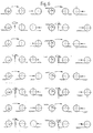
- the diagrams of FIG. 6 represent the different modes of winding the fabric on the cylinder 14 and the different unwinding direction allowing the different quilting variants that can be produced.
Landscapes
- Treatment Of Fiber Materials (AREA)
- Sewing Machines And Sewing (AREA)
- Chemical Or Physical Treatment Of Fibers (AREA)
- Details Of Garments (AREA)
- Massaging Devices (AREA)
- Details Of Cutting Devices (AREA)
- Folding Of Thin Sheet-Like Materials, Special Discharging Devices, And Others (AREA)
- Pile Receivers (AREA)
Abstract
Description
On connait dans l'industrie utilisant le tissu, naturel, synthétique ou en mélange, l'opération dite de matelassage de plusieurs épaisseurs de tissu en vue de la coupe selon un ou plusieurs gabarits, généralement cette opération s'effectue par la dépose en couches superposées du tissu lors du dévidement de la pièce supportée par un chariot mobile se déplaçant selon un mouvement alternatif le long d'un chemin de roulement solidaire de la table de coupe, le chariot support de pièces est doté ou non d'un dispositif de coupe permettant en fin de course déterdéterminée selon la longueur du matelassage désirée de couper le tissu afin que selon le type de tissu, lors du retour du chariot, une nouvelle couche soit déposée et ce la face avant du tissu de manière alternée entre deux couches ou dans le même sens au moyen d'une tourelle solidaire du support de tissu permettant la rotation de la pièce dudit tissu en fin de course. Ce mode de matelassage est délicat, il nécessite une surveillance accrue pour le contrôle de la superposition des couches afin qu'elle soit parfaite et d'autre part pour palier à la formation de plis durant la dépose occasionnés par le décalage important de la pièce de tissu par rapport à la table s'accentuant au fur et à mesure du dévidement dudit tissu, et de l'air compris entre la couche en cours de dépose et celle déjà déposée, ledit air selon la catégorie du tissu n'étant pas systématiquement chassé.We know in the industry using fabric, natural, synthetic or mixed, the so-called quilting operation of several thicknesses of fabric for cutting according to one or more templates, generally this operation is carried out by layering superimposed on the fabric during the unwinding of the workpiece supported by a mobile carriage moving in an alternating movement along a raceway integral with the cutting table, the workpiece support carriage may or may not have a cutting device allowing at the end of the determined course according to the length of the desired padding to cut the fabric so that according to the type of fabric, when the carriage returns, a new layer is deposited and this the front face of the fabric alternately between two layers or in the same direction by means of a turret secured to the fabric support allowing the part of said fabric to rotate at the end of its travel. This quilting mode is delicate, it requires increased monitoring to control the superposition of the layers so that it is perfect and on the other hand to compensate for the formation of folds during removal caused by the significant shift of the piece of fabric relative to the table increasing as the unwinding of said fabric, and the air between the layer being deposited and that already deposited, said air according to the category of fabric is not systematically removed .
L'invention a pour but de palier aux inconvénients précédemment exposés.The object of the invention is to overcome the drawbacks described above.
L'invention -a pour objet un procédé de matelassage de longueurs de tissus sur une table de coupe consistant à dévider d'une pièce de tissu maintenue sur un châssis prolongeant la table de coupe une longueur de tissu correspondant à la longueur du maielassage désirée tout en réenroulant simultanément sur un cylindre maintenu sur un bâti solidaire du chassis, puis une fois la longueur de tissu enroulée sur le cylindre celui-ci est déplace par un chariot mobile solidaire de la table de coupe et est acheminé à l'endroit désiré de la table de coupe afin d'être déposé, tissu emoulé en appui sur la table de coupe ou sur la ou les couches préalablement matelassées et déplacé par le chariot dans le sens opposé à l'enroulement du tissu provoquant la rotation du cylindre et le dévidement et matelassage du tissu après dévidement le cylindre est acheminé vers le chassis afin de réenrouler une nouvelle longueur de tissu.The subject of the invention is a method of quilting lengths of fabric on a cutting table consisting of unwinding from a piece of fabric held on a frame extending the cutting table a length of fabric corresponding to the length of the desired weaving by simultaneously rewinding on a cylinder maintained on a frame secured to the chassis, then once the length of fabric wound on the cylinder it is moved by a mobile carriage secured to the cutting table and is conveyed to the desired location on the cutting table in order to be deposited, fabric rolled up resting on the cutting table or on the previously padded layer or layers and moved by the carriage in the opposite direction to the winding of the fabric causing the rotation of the cylinder and the unwinding and quilting of the fabric after unwinding the cylinder is routed to the chassis to rewind a new length of fabric.
Le dispositif permettant l'application du procédé comporte un chassis prolongeant la table de coupe sur lequel sont maintenus une pièce de tissu et un bâti rotatif dans le sens horizontal doté de traverses rotatives dans le sens vertical recevant et maintenant en leur extrémité au moins un cylindre sur lequel est enroulée par rotation une longueur de tissu dévidée de la pièce correspondant à la longueur de matelasage désirée, le cylindre une fois la longueur de tissu enroulée et séparée de la pièce de tissu, après rotation des traverses et/ou pivotement du bâti est présenté à un chariot mobile guidé par un chemin de roulement solidaire de la table de coupe. ledit chariot étant doté de consoles mobiles afin d'extraire par élévation le cylindre des supports dont sont pourvues les extrémités des traverses et acheminer ce dernier en position haute à l'endroit désiré sur la table de coupe, ledit cylindre étant déposé sur la table de coupe ou sur la ou les couches de tissu préalablement matelassées et déplacé par le chariot afin d'en- gendier sa rotation dans le sens inverse de l'enroulement du tissu pour provoquer le déroulement du tissu et sa dépose et/ou son matelassage sur la table de coupe ou sur la ou les couches de tissu matelassées au prealable. en fin de dévidement le cylindre est à nouveau élevé et acheminé vers le bâti rotatif où il est déposé sur les supports des traverses dont la rotation ou celle du bâti présente ce dernier en vue de l'enroulement d'une nouvelle longueur ladite rotation ayant placé un second cylindre sur lequel a été enroulée une longueur de tissu durant le dévidement du précédent sur la table de coupe à l'aplomb du chariot mobile afin d'être extrait et acheminé à l'endroit désiré sur la table de coupe, les différentes opérations et commandes des organes d'entraînement étant synchronisées au moyen d'un ordinateur auquel les différents organes sont asservis.The device allowing the application of the process comprises a frame extending the cutting table on which are held a piece of fabric and a frame rotating in the horizontal direction provided with rotating crossbars in the vertical direction receiving and holding at their end at least one cylinder on which is wound by rotation a length of fabric unwound from the piece corresponding to the desired mattress length, the cylinder once the length of fabric wound and separated from the piece of fabric, after rotation of the crosspieces and / or pivoting of the frame is presented to a mobile carriage guided by a raceway secured to the cutting table. said carriage being provided with movable consoles in order to extract by elevation the cylinder from the supports which are provided with the ends of the crosspieces and convey the latter in the high position to the desired location on the cutting table, said cylinder being deposited on the cutting table cutting or on the layer or layers of fabric previously quilted and moved by the carriage in order to cause its rotation in the opposite direction of the winding of the fabric to cause the unwinding of the fabric and its deposition and / or quilting on the cutting table or on the pre-padded fabric layer (s). at the end of unwinding the cylinder is again raised and routed to the rotary frame where it is deposited on the supports of the sleepers whose rotation or that of the frame presents the latter for the purpose of winding a new length, said rotation having placed a second cylinder on which a length of fabric was wound during the unwinding of the previous one on the cutting table directly above the mobile carriage in order to be extracted and transported to the desired location on the cutting table, the different operations and controls of the drive members being synchronized by means of a computer to which the different members are controlled.
D'autres caractéristiques et avantages de l'invention ressortiront plus clairement de la descriptior qui va suivre faite en regard des dessins joints donnés à titre d'exemple non limitatif, où :
- - la figure 1 est une vue latérale du dispositif, un cylindre déposant une longueur de tissu tandis que sur un deuxième cylindre s'enroule une longueur de tissu,
- - la figure 2, une vue de dessus du chariot solidaire de la table de coupe,
- - la figure 3, le détail du bâti solidaire du chassis prolongeant la table de coupe,
- - la figure 4, le détail des traverses supportées par le bâti,
- - la figure 5, le mode de pincement du tissu sur le cylindre,
- - la figure 6, les différents modes d'enroulement du tissu sur le cylindre et dévidement de ce dernier en vue du matelassage.
- - Figure 1 is a side view of the device, a cylinder depositing a length of fabric while on a second cylinder is wrapped a length of fabric,
- FIG. 2, a top view of the carriage secured to the cutting table,
- - Figure 3, the details of built secured to the frame extending the cutting table
- - Figure 4, the detail of the sleepers supported by the frame,
- FIG. 5, the method of pinching the fabric on the cylinder,
- - Figure 6, the different modes of winding the fabric on the cylinder and unwinding the latter for quilting.
Tel que représenté figures 1 à 4, le dispositif comporte une table de coupe 1 dotée d'un chemin de roulement 2 servant de guide à un chariot mobile 3 pouvant se déplacer alternativement au moyen d'un moteur 4 impliquant par exempte un mouvement de rotation dans un sens ou l'autre à un arbre 5 par une transmission à roues et chaîne 6, ledit arbre 5 en ses extrémités sert d'axe aux roues 7 afin de provoquer le déplacement du chariot 3 lors de sa rotation, sur le chassis 8 est fixé de part et d'autre un guide vertical 9 à un système vis-écrous connu en soi.les écrous 10 mobiles dans le guide 9 sont reliés à une consoie 11 prolongée par un demi-palier 12 destiné à recevoir les extrémités 31 de l'axe 13 du cylindre 14. les vis 15 sont animées en rotation au moyen d'un moteur à double sens 16 relié par transmission 17 à un arbre 18 prolongé par des engrenages coniques 19 engrenant sur les roues 20 prolongeant les vis 15 et ce de façon à pouvoir élever ou abaisser le cylindre 14, en position élevée pour déplacer ledit cylindre 14 au-dessus de la table de coupe 1 afin de le placer à l'endroit désiré, en position abaissée pour dévider la longueur de tissu correspondant à la longueur du matelassage enroulée sur ledit cylindre lors du déplacement dans le sens contraire au sens d'enroulement dudit tissu et ce grâce au déplacement du chariot, le cylindre et de ce fait le tissu enroulé étant en appui sur la table de coupe 1 ou sur la ou les couches précédemment déposées et matelassées. Une fois le tissu dévidé du cylindre 14, ce dernier est élevé et acheminé par le chariot 3 vers un .chassis 21 en prolongement de la table de coupe 1, sur le chassis 21 est maintenu un bâti 22 forme de U, il est doté en sa partie centrale d'une tourelle 23 pourvue d'éléments et organes d'entraînement connus en soit lui permettant de pivoter sur au moins 180° ainsi qu'un dispositif d'élévation tel que vérin 23a, tandis qu'en extrémité des bras 24 deux traverses 25 pivotantes sont solidarisées au moyen d'un axe 26 maintenu sur des paliers 27 fixés sur les bras 24, ledit axe est relié par une transmission à chaîne 28 par exemple à un moteur 29 permettant d'entrainer en rotation ledit axe 28 par exemple à un mo- leur 29 permettant d'entraîner en rotation ledit axe 26 et de ce fait faire pivoter les traverses 25, ces dernières de part et d'autre de l'axe 26 sont dotées en leurs extrémités de demi-paliers 30 permettant de recevoir les extrémités 31 de l'axe 13 du cylindre 14, le cylindre 14 étant placé sur les demi-paliers 30 lors de son acheminement par le chariot 3 en position élevée, une fois que l'axe 13 du cylindre 14 est mis en place sur les paliers 30 des demi-paliers articulés 32 verrouillent par l'intermédiaire de vélins pneumatiques 33 par exemple les extrémités 31 de l'axe 13 de sorte à permettre le déplacement du cylindre 14 lors de la rotation des traverses 25 et ce afin de placer ledit cylindre 14 face à un dispositif à cylindres rotatifs 34 d'amenée de tissu, celui-ci étant dévidé de la pièce 35 maintenue sur le chassis 21 par les moyens appropriés connus en soi d'embarrage.As shown in Figures 1 to 4, the device comprises a cutting table 1 provided with a raceway 2 serving as a guide for a movable carriage 3 which can move alternately by means of a motor 4 implying for example a rotational movement in one direction or the other to a shaft 5 by a wheel and chain transmission 6, said shaft 5 at its ends serves as an axis for the wheels 7 in order to cause the movement of the carriage 3 during its rotation, on the chassis 8 is fixed on both sides a vertical guide 9 to a screw-nut system known per se. the nuts 10 movable in the guide 9 are connected to a rail 11 extended by a half-bearing 12 intended to receive the ends 31 of the
Tel que représenté figure 5 sur une génératrice du cylindre 14 est aménagée une rainure 36 dans laquelle est placé par exemple un élément gonflable 37 avant pour fonction de pincer la tranche 38 de tissu présentée par un chariot mobile 40 à mouvement alternatif disposé à la sortie du dispositif à cylindres rotatifs 34. celui-ci avant pour fonction de placer lors de son déplacement vers la rainure 36 du cylindre 14 en même temps que l'avance du tissu. la tranche 38 dudit tissu dans la rainure 36 afin d'être pincée lors du retrait du chariot 40 pour pouvoir enrouler le tissu sur le cylindre 14 lorsque celui-ci est animé de rotation au moyen d'un moteur 39 à double sens.Afin de couper le tissu une fois la longueur enroulée sur le cylindre, un dispositif de coupe 41 connu en soi est disposé à la sottie du dispositif cylindrique 34.As shown in Figure 5 on a generator of the
Suivant le sens d'enroulement du tissu sur le cylindre 14 et le type de matelassage désiré. selon impression du tissu, le cylindre chargé est présenté au chariot aprés rotation des traverses 25, tel que ou est présenté après rotation du bâti 22 Les schémas de la figure 6 représentent les différents modes d'enroulement du tissu sur le cylindre 14 et les différents sens de dévidement permettant les différentes variantes de matelassage qu'il est possible de réaliser.According to the direction of winding of the fabric on the
Afin de limiter les pertes de temps. il est utilisé deux cylindres 14 l'un étant en place sur le chariot en vue de son dévidement tandis que l'autre est en cours de chargement, le dépôt d'un cylindre 14 par le chariot 3 sur les traverses 25 étant effectué avant que le cylindre 14 chargé soit présenté aux consoles mobiles 11 du chariot 3.To limit the loss of time. two
Claims (10)
Priority Applications (1)
| Application Number | Priority Date | Filing Date | Title |
|---|---|---|---|
| AT84450003T ATE27948T1 (en) | 1983-02-11 | 1984-02-13 | DEVICE AND METHOD FOR LAYING UP PANELS. |
Applications Claiming Priority (2)
| Application Number | Priority Date | Filing Date | Title |
|---|---|---|---|
| FR8302361 | 1983-02-11 | ||
| FR8302361A FR2540848A1 (en) | 1983-02-11 | 1983-02-11 | METHOD AND DEVICE FOR QUILTING FABRIC LENGTHS |
Publications (2)
| Publication Number | Publication Date |
|---|---|
| EP0119147A1 true EP0119147A1 (en) | 1984-09-19 |
| EP0119147B1 EP0119147B1 (en) | 1987-06-24 |
Family
ID=9285899
Family Applications (1)
| Application Number | Title | Priority Date | Filing Date |
|---|---|---|---|
| EP84450003A Expired EP0119147B1 (en) | 1983-02-11 | 1984-02-13 | Method and device for spreading lengths of fabric |
Country Status (9)
| Country | Link |
|---|---|
| EP (1) | EP0119147B1 (en) |
| JP (1) | JPS6045670A (en) |
| AT (1) | ATE27948T1 (en) |
| AU (1) | AU2447084A (en) |
| DE (1) | DE3464357D1 (en) |
| ES (1) | ES8503620A1 (en) |
| FR (1) | FR2540848A1 (en) |
| GR (1) | GR81767B (en) |
| NZ (1) | NZ207133A (en) |
Cited By (1)
| Publication number | Priority date | Publication date | Assignee | Title |
|---|---|---|---|---|
| CN109809236A (en) * | 2019-04-03 | 2019-05-28 | 广州市兴世机械制造有限公司 | The box winding device of band storing |
Families Citing this family (5)
| Publication number | Priority date | Publication date | Assignee | Title |
|---|---|---|---|---|
| JPS60194170A (en) * | 1984-03-15 | 1985-10-02 | 東レ株式会社 | Impartment of crease to polyester fiber product |
| FR2619095B1 (en) * | 1987-08-03 | 1989-12-29 | Rey Alain | METHOD AND MACHINE FOR QUILTING ROLLS OF WOVEN, NONWOVEN, KNITTED OR OTHER MATERIALS IN THE TEXTILE INDUSTRY |
| JPH03146765A (en) * | 1989-10-27 | 1991-06-21 | Yamato Sewing Mach Seizo Kk | Automatic cloth cutting machine |
| CN113174743A (en) * | 2021-04-30 | 2021-07-27 | 梁波 | Wet piece of cloth preprocessing device with cutting function |
| CN115418848B (en) * | 2022-09-23 | 2024-02-13 | 绍兴博利豪家纺有限公司 | High-efficient fabric cutting machine |
Citations (1)
| Publication number | Priority date | Publication date | Assignee | Title |
|---|---|---|---|---|
| FR2496618A1 (en) * | 1980-12-18 | 1982-06-25 | Badets Alain | Carriage for cushion manufacture conveyor - has rollers running parallel to table with carrier for swivelling material roll |
-
1983
- 1983-02-11 FR FR8302361A patent/FR2540848A1/en active Granted
-
1984
- 1984-02-08 ES ES529563A patent/ES8503620A1/en not_active Expired
- 1984-02-09 GR GR73763A patent/GR81767B/el unknown
- 1984-02-10 JP JP59024222A patent/JPS6045670A/en active Pending
- 1984-02-10 AU AU24470/84A patent/AU2447084A/en not_active Abandoned
- 1984-02-13 DE DE8484450003T patent/DE3464357D1/en not_active Expired
- 1984-02-13 AT AT84450003T patent/ATE27948T1/en not_active IP Right Cessation
- 1984-02-13 EP EP84450003A patent/EP0119147B1/en not_active Expired
- 1984-02-13 NZ NZ207133A patent/NZ207133A/en unknown
Patent Citations (1)
| Publication number | Priority date | Publication date | Assignee | Title |
|---|---|---|---|---|
| FR2496618A1 (en) * | 1980-12-18 | 1982-06-25 | Badets Alain | Carriage for cushion manufacture conveyor - has rollers running parallel to table with carrier for swivelling material roll |
Cited By (2)
| Publication number | Priority date | Publication date | Assignee | Title |
|---|---|---|---|---|
| CN109809236A (en) * | 2019-04-03 | 2019-05-28 | 广州市兴世机械制造有限公司 | The box winding device of band storing |
| CN109809236B (en) * | 2019-04-03 | 2024-02-09 | 广州市兴世机械制造有限公司 | Box rolling equipment for strip storage |
Also Published As
| Publication number | Publication date |
|---|---|
| FR2540848A1 (en) | 1984-08-17 |
| AU2447084A (en) | 1984-08-16 |
| FR2540848B1 (en) | 1985-05-03 |
| EP0119147B1 (en) | 1987-06-24 |
| GR81767B (en) | 1984-12-12 |
| NZ207133A (en) | 1987-05-29 |
| ATE27948T1 (en) | 1987-07-15 |
| ES529563A0 (en) | 1985-03-16 |
| ES8503620A1 (en) | 1985-03-16 |
| JPS6045670A (en) | 1985-03-12 |
| DE3464357D1 (en) | 1987-07-30 |
Similar Documents
| Publication | Publication Date | Title |
|---|---|---|
| US3889892A (en) | Center start surface wind reel with automatic cut-off and transfer | |
| US5639045A (en) | Method and winding device for winding webs | |
| US3857524A (en) | Surface enveloper transfer winder | |
| CH666446A5 (en) | DEVICE FOR ADJUSTING THE POSITION OF TOOLS FOR WORKING SHEET MATERIALS. | |
| US4200245A (en) | Web feeding or winding-up apparatus | |
| FR2472530A1 (en) | APPARATUS FOR PROCESSING SHEET MATERIAL CONTAINED ON SUCTION SUPPORT | |
| FR2531940A1 (en) | APPARATUS FOR ASSEMBLING BANDS | |
| CN212173979U (en) | Double-station winding system | |
| CA2367952C (en) | Device and method for unwinding reels of web material | |
| US5628167A (en) | Method and apparatus for wrapping elongate load having generally circular or generally annular ends | |
| EP0119147B1 (en) | Method and device for spreading lengths of fabric | |
| EP0200604B1 (en) | Cloth spreading apparatus | |
| EP0223632B1 (en) | Unwinding device for bobbins | |
| FR2618770A1 (en) | FEEDING DEVICE FOR A MACHINE WORKING ON A MATERIAL MATERIAL IN STOPPING, IN PARTICULAR FOR A FLAT CUTTING PRESS | |
| EP0403408A1 (en) | Method and apparatus for automatically fitting spacer means between the panes in multiple glazing | |
| CA2081241C (en) | Device for winding webs of material onto winding shafts | |
| EP0261077A1 (en) | Reel winder | |
| US4015791A (en) | Apparatus for slitting belt material | |
| EP0156738A1 (en) | Device for winding a fabric during the various manufacturing stages | |
| CA1254129A (en) | Process and device for quilting pieces of fabric | |
| US4223850A (en) | Surface wind batcher and method of collecting material in roll form | |
| EP0266290B1 (en) | Apparatus and method for feeding a cutting machine | |
| FR2465572A1 (en) | Machine for slitting roll of fabric - has mechanism for advancing rotating roll towards rotating circular blade | |
| US7419117B2 (en) | Apparatus for winding up a web in rolls and a method for cutting off a length of the web | |
| FR2692237A1 (en) | Method and device for feeding rolled material to an adhesive preparation station. |
Legal Events
| Date | Code | Title | Description |
|---|---|---|---|
| PUAI | Public reference made under article 153(3) epc to a published international application that has entered the european phase |
Free format text: ORIGINAL CODE: 0009012 |
|
| AK | Designated contracting states |
Designated state(s): AT BE CH DE GB IT LI LU NL SE |
|
| 17P | Request for examination filed |
Effective date: 19850319 |
|
| GRAA | (expected) grant |
Free format text: ORIGINAL CODE: 0009210 |
|
| AK | Designated contracting states |
Kind code of ref document: B1 Designated state(s): AT BE CH DE GB IT LI LU NL SE |
|
| REF | Corresponds to: |
Ref document number: 27948 Country of ref document: AT Date of ref document: 19870715 Kind code of ref document: T |
|
| REF | Corresponds to: |
Ref document number: 3464357 Country of ref document: DE Date of ref document: 19870730 |
|
| ITF | It: translation for a ep patent filed | ||
| PG25 | Lapsed in a contracting state [announced via postgrant information from national office to epo] |
Ref country code: SE Effective date: 19880214 |
|
| PG25 | Lapsed in a contracting state [announced via postgrant information from national office to epo] |
Ref country code: LI Effective date: 19880229 Ref country code: CH Effective date: 19880229 Ref country code: LU Free format text: LAPSE BECAUSE OF NON-PAYMENT OF DUE FEES Effective date: 19880229 |
|
| PLBE | No opposition filed within time limit |
Free format text: ORIGINAL CODE: 0009261 |
|
| STAA | Information on the status of an ep patent application or granted ep patent |
Free format text: STATUS: NO OPPOSITION FILED WITHIN TIME LIMIT |
|
| 26N | No opposition filed | ||
| REG | Reference to a national code |
Ref country code: CH Ref legal event code: PL |
|
| PG25 | Lapsed in a contracting state [announced via postgrant information from national office to epo] |
Ref country code: BE Effective date: 19890228 |
|
| PGFP | Annual fee paid to national office [announced via postgrant information from national office to epo] |
Ref country code: NL Payment date: 19890228 Year of fee payment: 6 |
|
| BERE | Be: lapsed |
Owner name: ETCHEPARRE BERNARD Effective date: 19890228 Owner name: LECTRA SYSTEMES S.A. Effective date: 19890228 Owner name: ETCHEPARRE JEAN Effective date: 19890228 |
|
| PGFP | Annual fee paid to national office [announced via postgrant information from national office to epo] |
Ref country code: AT Payment date: 19890831 Year of fee payment: 6 Ref country code: GB Payment date: 19890831 Year of fee payment: 6 |
|
| PG25 | Lapsed in a contracting state [announced via postgrant information from national office to epo] |
Ref country code: DE Effective date: 19891101 |
|
| PG25 | Lapsed in a contracting state [announced via postgrant information from national office to epo] |
Ref country code: AT Effective date: 19900213 Ref country code: GB Effective date: 19900213 |
|
| PG25 | Lapsed in a contracting state [announced via postgrant information from national office to epo] |
Ref country code: NL Effective date: 19900901 |
|
| GBPC | Gb: european patent ceased through non-payment of renewal fee | ||
| NLV4 | Nl: lapsed or anulled due to non-payment of the annual fee | ||
| EUG | Se: european patent has lapsed |
Ref document number: 84450003.3 Effective date: 19880927 |