Wet piece of cloth preprocessing device with cutting function
Technical Field
The invention relates to the technical field of wet tissue preprocessing, in particular to a wet tissue preprocessing device with a cutting function.
Background
Wet wipes are generally made by soaking non-woven fabrics, which are non-woven fabrics formed by carding fiber raw materials into a single fiber state by a carding machine, then forming a net by means of air flow or machinery and the like, then solidifying the net by means of spunlace, needle punching or hot rolling and the like, and finally finishing the net.
Among the prior art need carry out preprocessing cutting after wet piece of cloth processing, then the packing is sold, but receive external force influence and take place folding or shrink easily when wet piece of cloth twines, when preprocessing handled, back when the wet piece of cloth cutting of folding or shrink appears the deformity easily, and every solitary wet piece of cloth cutting effect is not good, and is not pleasing to the eye and be unfavorable for selling.
Disclosure of Invention
The invention aims to provide a wet tissue preprocessing device with a cutting function, and aims to solve the technical problems that deformity is easy to occur after wet tissues are cut during preprocessing and cutting of wet tissues in the prior art, and the product is not attractive and is not easy to sell.
In order to solve the technical problems, the invention provides the following technical scheme: the utility model provides a wet piece of cloth preprocessing device with cutting function, includes material loading rotary drum, processing platform, processingequipment and cutting device, the material loading rotary drum is the level setting, the processing platform sets up the one side at the material loading rotary drum, processingequipment sets up the both sides at the processing platform, cutting device sets up the top at the processing platform and is connected with processingequipment.
Further, the processing device comprises a spreading assembly, the spreading assembly comprises a processing shell, two processing wheels, a driving motor, a gear belt, a moving frame and three pressing blocks, the processing shell is arranged on one side of the processing table and is higher than the processing table, a processing groove is formed in one side of the processing shell close to the processing table, the two processing wheels are respectively arranged at two ends of the processing groove close to the processing table, the gear belt is sleeved on the two processing wheels, the driving motor is arranged on the surface of the processing shell, the output end of the driving motor is connected with one of the processing wheels, the moving frame is arranged on the gear belt, the pressing blocks penetrate through the moving frame and are movably connected with the moving frame, one end of each pressing block is positioned above the side end of the processing table, the moving frame and the three pressing blocks are arranged on the gear belt at equal intervals, the spreading assemblies are arranged in two numbers, and the two spreading assemblies are symmetrically arranged on two sides of the processing table.
Further, the spreading assembly further comprises a first spring and an inclined edge separation blade, one end of the first spring is connected with the moving frame, the other end of the first spring is connected with one end, far away from the processing table, of the pressing block, the inclined edge separation blade is arranged at one end, close to the feeding rotary drum, of the processing shell, and the inclined edge separation blade is arranged at the top end of the processing shell.
Further, processingequipment still includes synchronous subassembly, synchronous subassembly includes synchronizing wheel and synchronous belt, the synchronizing wheel is provided with two, two the synchronizing wheel sets up the both ends in processing platform one side, synchronous belt cover is established on two synchronizing wheels, synchronous subassembly is provided with two and the symmetry sets up the both sides at the processing platform.
Further, one side of the processing table, which is close to the feeding rotary drum, is provided with a lifting rotary drum, and the lifting rotary drum is higher than the processing table.
Furthermore, cutting device includes the cutting frame, drives actuating cylinder and cutting knife, the cutting frame is provided with two, two the bottom of cutting frame is connected with two processing shells respectively, it sets up on the top of processing platform and is connected with two cutting frames to drive actuating cylinder, the cutting knife sets up on the output that drives actuating cylinder, the cutting knife is the groined type.
Furthermore, the cutting device also comprises a cutting groove, the cutting groove is arranged on the processing table, and the shape of the cutting groove is the same as that of the cutting knife.
Further, still be equipped with thrust unit on the processing platform, thrust unit includes push tank, catch bar, second spring and collects the box, the push tank has all been seted up to the both sides of processing platform, the catch bar sets up the top at the processing platform, the both ends of catch bar respectively with the push tank sliding fit of processing platform both sides, the one end of second spring is connected with the one end of catch bar, the other end of second spring is connected with the processing platform, the second spring is provided with two and symmetry and sets up in the both sides of processing platform, collect the box setting and keep away from the one end of material loading rotary drum at the processing platform.
Compared with the prior art, the invention has the beneficial effects that:
firstly, the processing wheels are driven to rotate by the driving motor when wet tissues are processed, the pressing blocks are driven by the gear belt to circularly move around the two processing wheels, the side ends of the wet tissues are pressed on the processing table when the first pressing block is in contact with the wet tissues, the processing wheels rotate, the pressing blocks on the two sides pull the two sides of the wet tissues to synchronously move, the second pressing block on the gear belt is in contact with the wet tissues, the four sides of the wet tissues are stretched and spread on the processing table by the four pressing blocks in the two processing shells, so that the cutting device can conveniently cut complete wet tissues, the distances among the three pressing blocks are the same, the three pressing blocks can circularly stretch and spread the wet tissues, the wet tissues are stretched and spread along the movement direction, and the wet tissues are prevented from being folded when being cut.
Secondly, when the wet tissue is stretched, the gear belt drives the moving frame to move circularly, when the moving frame moves to the center of the top end of the processing groove, the moving frame is contacted with the bevel edge baffle plate, the moving frame continues to move, the pressing block is extruded by the bevel edge baffle plate to move towards the processing table and move to the upper part of the center of the processing table, after the pressing block with the pressing block is contacted with the wet tissue, the pressing block leaves the bevel edge baffle plate, the pressing block moves to the edge of the wet tissue from the center of the wet tissue under the pulling of the first spring, the folded part at the center of the wet tissue is spread by the two pressing blocks, the complete spreading of the wet tissue perpendicular to the moving direction is ensured, and the four corners of the wet tissue are completely spread.
Thirdly, when wet tissues are machined, after the wet tissues are cut by the cutting device, the pushing block close to the feeding rotary drum moves to drive the pushing rod to move, the cut wet tissues are pushed into the collecting box through the pushing rod, and after the pushing block rotates to the position above the machining wheel, the pushing rod is pulled to return to the initial position through the second spring, so that the stacking of the cut wet tissues is reduced, and the wet tissues are prevented from being repeatedly cut to cause damage to the wet tissues.
Drawings
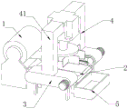
FIG. 1 is a schematic perspective view of the present invention;
FIG. 2 is a partial perspective view of the present invention;
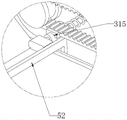
FIG. 3 is an enlarged view taken at A in FIG. 2;
FIG. 4 is an enlarged view at B in FIG. 2;
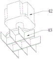
FIG. 5 is a schematic perspective view of a portion of the cutting device of the present invention;
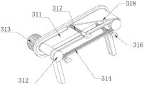
fig. 6 is a partial sectional structural view of the processing apparatus of the present invention.
The reference numbers in the figures are:
the automatic cutting machine comprises a feeding rotary drum 1, a lifting rotary drum 11, a processing table 2, a processing device 3, a spreading assembly 31, a processing shell 311, a processing wheel 312, a driving motor 313, a gear belt 314, a moving frame 315, a pressing block 316, a first spring 317, a bevel edge baffle 318, a synchronizing assembly 32, a synchronizing wheel 321, a synchronizing belt 322, a cutting device 4, a cutting frame 41, a driving cylinder 42, a cutting knife 43, a cutting groove 44, a pushing device 5, a pushing groove 51, a pushing rod 52, a second spring 53 and a collecting box 54.
Detailed Description
In order to make the objects, technical solutions and advantages of the present invention more apparent, the present invention is described in further detail below with reference to the accompanying drawings and embodiments. It should be understood that the specific embodiments described herein are merely illustrative of the invention and are not intended to limit the invention.
In the description of the present invention, it is to be understood that the terms "longitudinal", "lateral", "upper", "lower", "front", "rear", "left", "right", "vertical", "horizontal", "top", "bottom", "inner", "outer", and the like, indicate orientations or positional relationships based on those shown in the drawings, are merely for convenience of description of the present invention, and do not indicate or imply that the referenced devices or elements must have a particular orientation, be constructed and operated in a particular orientation, and thus, are not to be construed as limiting the present invention.
Referring to fig. 1 to 6, the invention provides a wet tissue preprocessing device with a cutting function, which comprises a feeding rotary drum 1, a processing table 2, a processing device 3 and a cutting device 4, wherein the feeding rotary drum 1 is horizontally arranged, the processing table 2 is arranged at one side of the feeding rotary drum 1, the processing device 3 is arranged at two sides of the processing table 2, and the cutting device 4 is arranged above the processing table 2 and connected with the processing device 3, and the invention has the advantages that when the device works, a wet tissue winding drum to be processed is sleeved on the feeding rotary drum 1, the wet tissue can be pulled out and spread on the processing table 2 through the processing device 3, the folded part of the wet tissue is unfolded, the deformity caused by folding the wet tissue after cutting can be prevented, and the wet tissue is cut into a plurality of pieces through the cutting device 4, so as to finish the preprocessing and cutting of the wet tissue.
Specifically, the processing device 3 includes a spreading assembly 31, the spreading assembly 31 includes a processing shell 311, two processing wheels 312, a driving motor 313, a gear belt 314, a moving frame 315 and a pressing block 316, the processing shell 311 is disposed on one side of the processing table 2 and is higher than the processing table 2, a processing groove is disposed on one side of the processing shell 311 close to the processing table 2, two processing wheels 312 are disposed, the two processing wheels 312 are respectively disposed on two ends of the processing groove close to the processing table 2, the gear belt 314 is sleeved on the two processing wheels 312, the driving motor 313 is disposed on the surface of the processing shell 311, an output end of the driving motor 313 is connected with one of the processing wheels 312, the moving frame 315 is disposed on the gear belt 314, the pressing block 316 passes through the moving frame 315 and is movably connected with the moving frame 315, one end of the pressing block 316 is located above a side end of the processing table 2, the movable frame 315 and the pressing blocks 316 are provided with three, the three pressing blocks 316 are equidistantly arranged on the gear belt 314, the spreading assemblies 31 are provided with two, the two spreading assemblies 31 are symmetrically arranged on two sides of the processing table 2, and the functions of the movable frame and the pressing blocks 316 are that the processing wheel 312 is driven to rotate by the driving motor 313, the pressing blocks 316 are driven by the gear belt 314 to circularly move around the two processing wheels 313, when the first pressing block 316 is contacted with the wet tissue, the side end of the wet tissue is pressed on the processing table 2, the processing wheel 312 rotates, the pressing blocks 316 on two sides pull two sides of the wet tissue to synchronously move, when the second pressing block 316 on the gear belt 314 is contacted with the wet tissue, the four sides of the wet tissue are stretched and spread on the processing table 2 by the four pressing blocks 316 in the two processing shells 311, so that the cutting device 4 can cut complete wet tissue conveniently, and the distances between the three pressing blocks 316 are the same, the three press blocks 316 can cyclically stretch and spread the wet tissues.
Specifically, the spreading assembly 31 further comprises a first spring 317 and a bevel edge baffle 318, one end of the first spring 317 is connected with the moving frame 315, the other end of the first spring 317 is connected with one end of the pressing block 316 far away from the processing table 2, one end of the processing shell 311 close to the feeding drum 1 is provided with the bevel edge baffle 318, the bevel edge baffle 318 is arranged at the top end of the processing shell 311, the bevel edge baffle 318 is used for driving the moving frame 315 to move circularly by the gear belt 314, when the moving frame 315 moves to the center of the top end of the processing tank and contacts with the bevel edge baffle 318, the moving frame 315 continues to move, the pressing block 316 is pressed by the bevel edge baffle 318 to move towards the processing table 2 and move to the upper part of the center of the processing table 2, after the belt pressing block 316 contacts with the wet towel, the pressing block 316 leaves the bevel edge baffle 318 and moves from the center of the wet towel to the edge of the wet towel under the pulling of the first spring 317, the folding position at the center of the wet tissue is spread by the two pressing blocks 316, so that the integrity of the wet tissue during cutting is ensured.
Specifically, processingequipment 3 still includes synchronizing assembly 32, synchronizing assembly 32 includes synchronizing wheel 321 and synchronous belt 322, synchronizing wheel 321 is provided with two, two synchronizing wheel 321 sets up the both ends in processing platform 2 one side, synchronous belt 322 cover is established on two synchronizing wheel 321, synchronizing assembly 32 is provided with two and the symmetry sets up the both sides at processing platform 2, and its effect lies in, presses the wet piece of cloth on synchronous belt 322 after pressing piece 316 and wet piece of cloth contact, and pressing piece 316 drives synchronous belt 322 and removes, fixes the wet piece of cloth and stimulates wet piece of cloth and remove through pressing piece 316 and synchronous belt 322.
Specifically, a lifting rotary drum 11 is arranged on one side of the processing table 2 close to the feeding rotary drum 1, the lifting rotary drum 11 is higher than the processing table 2, and the lifting rotary drum 11 has the function of raising the height of the wet tissues and increasing the contact effect of the pressing block 316 and the wet tissues.
Specifically, the cutting device 4 includes a cutting frame 41, a driving cylinder 42 and two cutting knives 43, the cutting frame 41 is provided with two, the bottom ends of the two cutting frames 41 are respectively connected with the two processing shells 311, the driving cylinder 42 is arranged at the top end of the processing table 2 and connected with the two cutting frames 41, the cutting knives 43 are arranged at the output end of the driving cylinder 42, the cutting knives 43 are in a # -shape, the function of the cutting knives is that when the processing device 3 stretches and spreads the wet tissue on the processing table 2, the cutting knives 43 are driven by the driving cylinder 42 to cut the wet tissue into small pieces, and one side of the cutting knives 43 close to the feeding rotary drum 1 is provided with a closed cutter, so that the wet tissue can be conveniently cut off.
Specifically, the cutting device 4 further comprises a cutting groove 44, the cutting groove 44 is formed in the processing table 2, the cutting groove 44 and the cutting knife 43 are identical in structure, the cutting effect of the cutting device can be enhanced through the cutting groove 44, and the problem that the cutting effect is poor when the wet tissue is cut off is solved.
Specifically, the processing table 2 is further provided with a pushing device 5, the pushing device 5 comprises a pushing groove 51, a pushing rod 52, a second spring 53 and a collecting box 54, the pushing groove 51 is formed on both sides of the processing table 2, the pushing rod 52 is arranged above the processing table 2, both ends of the pushing rod 52 are respectively in sliding fit with the pushing grooves 51 on both sides of the processing table 2, one end of the second spring 53 is connected with one end of the pushing rod 52, the other end of the second spring 53 is connected with the processing table 2, the second spring 53 is provided with two ends and symmetrically arranged on both sides of the processing table 2, the collecting box 54 is arranged at one end of the processing table 2 far away from the feeding drum 1, when the cutting device 4 cuts the wet tissues, the pushing rod 52 is driven to move when the pressing block 316 close to the feeding drum 1 moves, the cut wet tissues are pushed to the collecting box 54 by the pushing rod 52, when the pressing block 316 rotates above the processing wheel 312, the pushing rod 52 is pulled by the second spring 53 to return to the initial position.
The working principle of the invention is as follows: when the invention is used, a wet tissue winding drum is arranged on an feeding rotary drum 1, one end of a wet tissue which is drawn out is placed on a processing table 2, three pressing blocks 316 are driven to move by a driving motor 313, when the first pressing block 316 moves, the pressing block 316 is extruded to the central position of the wet tissue by a bevel edge baffle 318, after the pressing block 316 contacts the wet tissue, the pressing block 316 moves to two sides of the wet tissue, the part where the wet tissue is folded together is stretched and unfolded, two ends of the wet tissue are pressed on a synchronous belt 322 by the pressing blocks 316 at two sides, a gear belt 314 continues to rotate, after the other two sides of the wet tissue are stretched and pressed by the second pressing block 316, the wet tissue is completely spread by the four pressing blocks 316, after the wet tissue is cut into complete small pieces by a wet tissue cutting knife 43, the pressing blocks 316 continue to move, a new wet tissue is pulled to be spread on the processing table 2, and a push rod 52 is driven to move in the pulling process, and the cut small pieces of the wet tissues are pushed into a collection box 54, so that the automatic processing and cutting of the wet tissues are realized.
Finally, it should be noted that: the above embodiments are only used to illustrate the technical solution of the present invention, and not to limit the same; while the invention has been described in detail and with reference to the foregoing embodiments, it will be understood by those skilled in the art that: the technical solutions described in the foregoing embodiments may still be modified, or some or all of the technical features may be equivalently replaced; and the modifications or the substitutions do not make the essence of the corresponding technical solutions depart from the scope of the technical solutions of the embodiments of the present invention.