EP0118751B1 - Véhicule ferroviaire à bogie permettant de réduire les usures des boudins de roues - Google Patents
Véhicule ferroviaire à bogie permettant de réduire les usures des boudins de roues Download PDFInfo
- Publication number
- EP0118751B1 EP0118751B1 EP84101221A EP84101221A EP0118751B1 EP 0118751 B1 EP0118751 B1 EP 0118751B1 EP 84101221 A EP84101221 A EP 84101221A EP 84101221 A EP84101221 A EP 84101221A EP 0118751 B1 EP0118751 B1 EP 0118751B1
- Authority
- EP
- European Patent Office
- Prior art keywords
- connecting rod
- bogie
- railway vehicle
- articulation
- vehicle according
- Prior art date
- Legal status (The legal status is an assumption and is not a legal conclusion. Google has not performed a legal analysis and makes no representation as to the accuracy of the status listed.)
- Expired
Links
- 229920001971 elastomer Polymers 0.000 claims description 6
- 239000000806 elastomer Substances 0.000 claims description 6
- 238000013016 damping Methods 0.000 claims description 2
- 238000006243 chemical reaction Methods 0.000 description 6
- 230000006835 compression Effects 0.000 description 5
- 238000007906 compression Methods 0.000 description 5
- 230000003137 locomotive effect Effects 0.000 description 3
- 239000002184 metal Substances 0.000 description 2
- 239000007787 solid Substances 0.000 description 2
- 238000009434 installation Methods 0.000 description 1
- 230000000750 progressive effect Effects 0.000 description 1
- 230000035939 shock Effects 0.000 description 1
Images
Classifications
-
- B—PERFORMING OPERATIONS; TRANSPORTING
- B61—RAILWAYS
- B61F—RAIL VEHICLE SUSPENSIONS, e.g. UNDERFRAMES, BOGIES OR ARRANGEMENTS OF WHEEL AXLES; RAIL VEHICLES FOR USE ON TRACKS OF DIFFERENT WIDTH; PREVENTING DERAILING OF RAIL VEHICLES; WHEEL GUARDS, OBSTRUCTION REMOVERS OR THE LIKE FOR RAIL VEHICLES
- B61F5/00—Constructional details of bogies; Connections between bogies and vehicle underframes; Arrangements or devices for adjusting or allowing self-adjustment of wheel axles or bogies when rounding curves
- B61F5/38—Arrangements or devices for adjusting or allowing self- adjustment of wheel axles or bogies when rounding curves, e.g. sliding axles, swinging axles
- B61F5/44—Adjustment controlled by movements of vehicle body
-
- B—PERFORMING OPERATIONS; TRANSPORTING
- B61—RAILWAYS
- B61F—RAIL VEHICLE SUSPENSIONS, e.g. UNDERFRAMES, BOGIES OR ARRANGEMENTS OF WHEEL AXLES; RAIL VEHICLES FOR USE ON TRACKS OF DIFFERENT WIDTH; PREVENTING DERAILING OF RAIL VEHICLES; WHEEL GUARDS, OBSTRUCTION REMOVERS OR THE LIKE FOR RAIL VEHICLES
- B61F5/00—Constructional details of bogies; Connections between bogies and vehicle underframes; Arrangements or devices for adjusting or allowing self-adjustment of wheel axles or bogies when rounding curves
Definitions
- the present invention relates to a railway vehicle comprising a body and two motor bogies, each of which is connected to the body by a single connecting rod, one of the connecting rods working in compression while the other works in traction, and vice versa, according to the direction of travel.
- Document DE-A-2 604 769 describes a railway vehicle with a motor bogie connected to the body by a single connecting rod of constant cross section, the latter ending on the side of the bogie by an elastic ball joint and on the side of the body with a articulation with elastic discs.
- Document GB-A - 2,055,079 describes a railway vehicle with two motor bogies, each of which is connected to the body by a single connecting rod, one of the connecting rods working in compression and the other in traction, and vice versa, depending on the direction of travel. But each of these connecting rods is articulated between a point on the axis of the bogie distant from the end of the body and a point of the body relatively close to the middle of the latter.
- the object of the present invention is to reduce wear on the flanges of the wheels in the course of curved tracks.
- each of the connecting rods is articulated between a point on the longitudinal axis of the bogie close to the end of the body and a point on the longitudinal axis of the body close to said end .
- the articulation of the connecting rod does not include any play.
- the articulation between the connecting rod and the chassis formed either by the body or by the bogie comprises an axis integral with said chassis and a ball joint integral with the connecting rod cooperating with each other.
- the articulation between the connecting rod and the chassis constituted either by the body or by the bogie comprises elastomer damping elements.
- the connecting rod is full, at least at its ends, and of cross section progressively increasing from its ends.
- it is hollow in the form of a cylindrical tube in the middle.
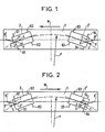
- Figures 1 and 2 show the distribution of forces in a motor vehicle according to the invention traveling a curved track.
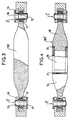
- FIG. 3 represents a schematic side view of a connecting rod according to the invention and of its articulations.
- the rear bogie 2 ' As for the rear bogie 2 ', it pulls the body 1 by means of the connecting rod 4'-6' disposed at the rear of the rear bogie 2 '.
- the force F transmitted by the connecting rod on the body acts this time in traction but the reactions R3, R4 of the track on the axles and balancing the transverse component T are of opposite direction to the reactions S3 and S4 due to the sliding of the axles on the rail and therefore always reduce its value.
- the bogie 2 is the front bogie and it pushes the body 1 by means of the connecting rod 4'-6 '.
- the rod 4'-6 ' is arranged this time at the front of the bogie before 2', and it works in compression.
- the bogie 2 is the rear bogie and it pulls the body 1 by means of the connecting rod 7'-9 '.
- the rod 7'-9 ' is disposed at the rear of the rear bogie 2 and it works in traction.
- connecting rod 100 connecting the points of articulation 7 'and 9' or 4 'and 6'.
- the connecting rod 100 is dimensioned so that it can withstand compression or tensile forces and for this the section of the connecting rod 100, metallic and solid, is greater in the middle of the connecting rod than at the ends, the variation in the section being progressive.
- the connecting rod 100 has at its ends ball joints 11 which cooperate with and are crossed by the axes 12 and 13 arranged in fixed yokes 14 and 15 respectively in the body and bogie chassis. It should be noted that instead of ball joints such as 11, it is possible to envisage orifices in the ends of the connecting rods ensuring an equivalent role which is to transfer the forces from the yoke to the connecting rod or vice versa and to allow rotation of the connecting rod around of the axis.
- the axes 12 and 13 have reverse stop heads 16, 17 in order to facilitate their installation, but heads arranged in the same direction can also be envisaged.
- a connecting rod 100 ′ represents a variant of the connecting rod 100.
- the connecting rod 100 ′ is made up of metal ends 18 and 19 of progressively increasing sections and solid and of a metallic and hollow central portion 20 in the form of a cylindrical tube, for example, welded to the ends 18 and 19 by welds such as 21.
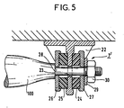
- FIG. 5 we see an articulation such as 7 'remarkable in that it comprises elastomer elements which have the advantage of absorbing shocks.
- a connecting rod 100 (or 100 ') passing through a fixed part 22 secured to the body or bogie chassis.
- the fixed part 22 includes an orifice 23 through which the end of the connecting rod 100 passes.
- On this end of the connecting rod 100 are mounted two elastomer elements 24, 25 held in position by two metal stops 26, 27; one of the stops 26 is supported on a shoulder 28 of the connecting rod 100, the other stop 26 is supported by a washer 29 on a nut 30.
- the elastomer elements 24, 25 provide the transfer forces from the connecting rod 100 to the fixed part 22 or vice versa.
- the applications of the device of the present invention are in the field of fitting out bogies and rail vehicle chassis as well as their connections.
Landscapes
- Engineering & Computer Science (AREA)
- Mechanical Engineering (AREA)
- Shafts, Cranks, Connecting Bars, And Related Bearings (AREA)
- Railway Tracks (AREA)
- Handcart (AREA)
- Vibration Prevention Devices (AREA)
- Vibration Dampers (AREA)
- Vehicle Waterproofing, Decoration, And Sanitation Devices (AREA)
Applications Claiming Priority (2)
| Application Number | Priority Date | Filing Date | Title |
|---|---|---|---|
| FR8301851 | 1983-02-07 | ||
| FR8301851A FR2540451B1 (fr) | 1983-02-07 | 1983-02-07 | Vehicule ferroviaire a bogie permettant de reduire les usures de boudins des roues |
Publications (2)
| Publication Number | Publication Date |
|---|---|
| EP0118751A1 EP0118751A1 (fr) | 1984-09-19 |
| EP0118751B1 true EP0118751B1 (fr) | 1987-02-04 |
Family
ID=9285647
Family Applications (1)
| Application Number | Title | Priority Date | Filing Date |
|---|---|---|---|
| EP84101221A Expired EP0118751B1 (fr) | 1983-02-07 | 1984-02-07 | Véhicule ferroviaire à bogie permettant de réduire les usures des boudins de roues |
Country Status (7)
| Country | Link |
|---|---|
| EP (1) | EP0118751B1 (da) |
| KR (1) | KR920001297B1 (da) |
| DK (1) | DK52384A (da) |
| ES (1) | ES529491A0 (da) |
| FR (1) | FR2540451B1 (da) |
| NO (1) | NO159439C (da) |
| PT (1) | PT78065B (da) |
Families Citing this family (2)
| Publication number | Priority date | Publication date | Assignee | Title |
|---|---|---|---|---|
| RU2180632C2 (ru) * | 1999-07-27 | 2002-03-20 | Акционерное общество закрытого типа "Спецремонт" | Устройство для крепления серповидной подвески к корпусу редуктора электропоезда |
| RU2164876C1 (ru) * | 1999-07-27 | 2001-04-10 | Акционерное общество закрытого типа "Спецремонт" | Корпус редуктора электропоезда с серповидной подвеской |
Family Cites Families (5)
| Publication number | Priority date | Publication date | Assignee | Title |
|---|---|---|---|---|
| DE1803069A1 (de) * | 1968-10-15 | 1970-04-23 | Augsburg Nuernberg Ag Zweignie | Verbindung eines Drehgestelles mit dem Wagenkasten eines Schienenfahrzeuges mittels Lenkern |
| BE788855A (fr) * | 1972-01-17 | 1973-01-02 | Gen Steel Ind Inc | Suspension de locomotive. |
| CH556260A (de) * | 1972-06-30 | 1974-11-29 | Waggon Union Gmbh | Eisenbahngueterwagen mit drehgestellen. |
| DE2604769C3 (de) * | 1976-02-07 | 1981-07-23 | M.A.N. Maschinenfabrik Augsburg-Nürnberg AG, 8500 Nürnberg | Einrichtung zur Führung eines Schienenfahrzeug-Drehgestelles am Untergestell des Wagenkastens |
| CH638731A5 (de) * | 1979-07-11 | 1983-10-14 | Schweizerische Lokomotiv | Schienenfahrzeug. |
-
1983
- 1983-02-07 FR FR8301851A patent/FR2540451B1/fr not_active Expired
-
1984
- 1984-02-06 NO NO840430A patent/NO159439C/no unknown
- 1984-02-06 PT PT78065A patent/PT78065B/pt not_active IP Right Cessation
- 1984-02-06 ES ES529491A patent/ES529491A0/es active Granted
- 1984-02-06 DK DK52384A patent/DK52384A/da not_active Application Discontinuation
- 1984-02-07 EP EP84101221A patent/EP0118751B1/fr not_active Expired
- 1984-02-07 KR KR1019840000568A patent/KR920001297B1/ko not_active Expired
Also Published As
| Publication number | Publication date |
|---|---|
| NO840430L (no) | 1984-08-08 |
| ES8500156A1 (es) | 1984-10-01 |
| FR2540451A1 (fr) | 1984-08-10 |
| DK52384D0 (da) | 1984-02-06 |
| DK52384A (da) | 1984-08-08 |
| FR2540451B1 (fr) | 1985-12-20 |
| EP0118751A1 (fr) | 1984-09-19 |
| NO159439C (no) | 1988-12-28 |
| KR920001297B1 (ko) | 1992-02-10 |
| KR840007543A (ko) | 1984-12-08 |
| ES529491A0 (es) | 1984-10-01 |
| PT78065B (fr) | 1986-09-11 |
| NO159439B (no) | 1988-09-19 |
| PT78065A (fr) | 1984-03-01 |
Similar Documents
| Publication | Publication Date | Title |
|---|---|---|
| CA2121995C (fr) | Dispositif d'amortissement de choc | |
| CA2681344C (fr) | Dispositif de suspension primaire d'un bogie de vehicule ferroviaire | |
| EP0409128B1 (fr) | Bogie articulé pour véhicules ferroviaires | |
| CA1328055C (fr) | Vehicule ferroviaire equipe, au niveau de chaque bogie, d'une barre anti-roulis agissant sur la suspension secondaire | |
| CA2487047A1 (fr) | Dispositif de liaison souple entre un longeron flexible et une boite d'essieu | |
| EP3222485B1 (fr) | Bogie de vehicule ferroviaire comprenant un dispositif de suspension primaire decale | |
| FR2513583A1 (fr) | Bogie a orientation forcee pour vehicule ferroviaire | |
| EP0118751B1 (fr) | Véhicule ferroviaire à bogie permettant de réduire les usures des boudins de roues | |
| EP0177424A1 (fr) | Dispositif d'intercirculation entre deux modules de rame ferroviaire | |
| US2204087A (en) | Tandem axle assembly | |
| EP3222486B1 (fr) | Bogie de véhicule ferroviaire comprenant un châssis abaissé | |
| FR2563487A1 (fr) | Bogie et vehicule ferroviaire ainsi que procede pour realiser une suspension de secours | |
| US2367751A (en) | Wheel mounting | |
| EP0277059B1 (fr) | Véhicule ferroviaire à charge répartie sur les quatre essieux orientables par rapport à la caisse | |
| FR2760420A1 (fr) | Vehicule ferroviaire comprenant une superstructure soutenue par un chassis auquel sont associes les bogies, ce chassis presentant au moins une extremite independante de cette superstructure et deformable de facon controlee | |
| FR2645800A1 (fr) | Train de roues notamment du type mac-pherson a traverse inferieure de filtrage | |
| CA1201019A (fr) | Bogie a essieux orientables | |
| CH423867A (fr) | Attelage automatique à simple traction pour véhicules de chemins de fer | |
| EP0104990A1 (fr) | Dispositif de maintien transversal d'une barre anti-dévers | |
| EP0061944B1 (fr) | Train de roues pour véhicule | |
| EP4074572B1 (fr) | Bogie moteur de véhicule ferroviaire | |
| FR2491850A1 (fr) | Bogie de chemin de fer autodirecteur | |
| FR2490171A1 (fr) | Bogie muni d'une poutre transversale pour l'appui de la caisse d'un vehicule ferroviaire | |
| BE354492A (da) | ||
| FR2711583A1 (fr) | Dispositif de suspension pour train arrière de véhicule automobile. |
Legal Events
| Date | Code | Title | Description |
|---|---|---|---|
| PUAI | Public reference made under article 153(3) epc to a published international application that has entered the european phase |
Free format text: ORIGINAL CODE: 0009012 |
|
| AK | Designated contracting states |
Designated state(s): BE FR NL SE |
|
| 17P | Request for examination filed |
Effective date: 19850312 |
|
| RAP1 | Party data changed (applicant data changed or rights of an application transferred) |
Owner name: ALSTHOM |
|
| GRAA | (expected) grant |
Free format text: ORIGINAL CODE: 0009210 |
|
| AK | Designated contracting states |
Kind code of ref document: B1 Designated state(s): BE FR NL SE |
|
| PLBI | Opposition filed |
Free format text: ORIGINAL CODE: 0009260 |
|
| 26 | Opposition filed |
Opponent name: ASEA AKTIEBOLAG Effective date: 19871022 |
|
| NLR1 | Nl: opposition has been filed with the epo |
Opponent name: ASEA AKTIEBOLAG |
|
| PGFP | Annual fee paid to national office [announced via postgrant information from national office to epo] |
Ref country code: NL Payment date: 19900228 Year of fee payment: 7 |
|
| RDAG | Patent revoked |
Free format text: ORIGINAL CODE: 0009271 |
|
| STAA | Information on the status of an ep patent application or granted ep patent |
Free format text: STATUS: PATENT REVOKED |
|
| 27W | Patent revoked |
Effective date: 19891124 |
|
| NLR2 | Nl: decision of opposition | ||
| PGFP | Annual fee paid to national office [announced via postgrant information from national office to epo] |
Ref country code: SE Payment date: 19910118 Year of fee payment: 8 |
|
| PGFP | Annual fee paid to national office [announced via postgrant information from national office to epo] |
Ref country code: BE Payment date: 19910124 Year of fee payment: 8 |
|
| PGFP | Annual fee paid to national office [announced via postgrant information from national office to epo] |
Ref country code: FR Payment date: 19910131 Year of fee payment: 8 |
|
| BERE | Be: lapsed |
Owner name: ALSTHOM Effective date: 19920228 |
|
| EUG | Se: european patent has lapsed |
Ref document number: 84101221.4 Effective date: 19900718 |