EP0117992B1 - Support for liftable and turnable lying and sitting arrangements - Google Patents
Support for liftable and turnable lying and sitting arrangements Download PDFInfo
- Publication number
- EP0117992B1 EP0117992B1 EP84100653A EP84100653A EP0117992B1 EP 0117992 B1 EP0117992 B1 EP 0117992B1 EP 84100653 A EP84100653 A EP 84100653A EP 84100653 A EP84100653 A EP 84100653A EP 0117992 B1 EP0117992 B1 EP 0117992B1
- Authority
- EP
- European Patent Office
- Prior art keywords
- clamping
- support
- vertical support
- boom
- seat
- Prior art date
- Legal status (The legal status is an assumption and is not a legal conclusion. Google has not performed a legal analysis and makes no representation as to the accuracy of the status listed.)
- Expired
Links
Images

Classifications
-
- A—HUMAN NECESSITIES
- A61—MEDICAL OR VETERINARY SCIENCE; HYGIENE
- A61G—TRANSPORT, PERSONAL CONVEYANCES, OR ACCOMMODATION SPECIALLY ADAPTED FOR PATIENTS OR DISABLED PERSONS; OPERATING TABLES OR CHAIRS; CHAIRS FOR DENTISTRY; FUNERAL DEVICES
- A61G7/00—Beds specially adapted for nursing; Devices for lifting patients or disabled persons
- A61G7/10—Devices for lifting patients or disabled persons, e.g. special adaptations of hoists thereto
- A61G7/1001—Devices for lifting patients or disabled persons, e.g. special adaptations of hoists thereto specially adapted for specific applications
- A61G7/1003—Devices for lifting patients or disabled persons, e.g. special adaptations of hoists thereto specially adapted for specific applications mounted on or in combination with a bath-tub
-
- A—HUMAN NECESSITIES
- A61—MEDICAL OR VETERINARY SCIENCE; HYGIENE
- A61G—TRANSPORT, PERSONAL CONVEYANCES, OR ACCOMMODATION SPECIALLY ADAPTED FOR PATIENTS OR DISABLED PERSONS; OPERATING TABLES OR CHAIRS; CHAIRS FOR DENTISTRY; FUNERAL DEVICES
- A61G7/00—Beds specially adapted for nursing; Devices for lifting patients or disabled persons
- A61G7/10—Devices for lifting patients or disabled persons, e.g. special adaptations of hoists thereto
- A61G7/1013—Lifting of patients by
- A61G7/1019—Vertical extending columns or mechanisms
-
- A—HUMAN NECESSITIES
- A61—MEDICAL OR VETERINARY SCIENCE; HYGIENE
- A61G—TRANSPORT, PERSONAL CONVEYANCES, OR ACCOMMODATION SPECIALLY ADAPTED FOR PATIENTS OR DISABLED PERSONS; OPERATING TABLES OR CHAIRS; CHAIRS FOR DENTISTRY; FUNERAL DEVICES
- A61G7/00—Beds specially adapted for nursing; Devices for lifting patients or disabled persons
- A61G7/10—Devices for lifting patients or disabled persons, e.g. special adaptations of hoists thereto
- A61G7/1049—Attachment, suspending or supporting means for patients
- A61G7/1059—Seats
-
- A—HUMAN NECESSITIES
- A61—MEDICAL OR VETERINARY SCIENCE; HYGIENE
- A61G—TRANSPORT, PERSONAL CONVEYANCES, OR ACCOMMODATION SPECIALLY ADAPTED FOR PATIENTS OR DISABLED PERSONS; OPERATING TABLES OR CHAIRS; CHAIRS FOR DENTISTRY; FUNERAL DEVICES
- A61G7/00—Beds specially adapted for nursing; Devices for lifting patients or disabled persons
- A61G7/10—Devices for lifting patients or disabled persons, e.g. special adaptations of hoists thereto
- A61G7/1073—Parts, details or accessories
- A61G7/1076—Means for rotating around a vertical axis
-
- A—HUMAN NECESSITIES
- A61—MEDICAL OR VETERINARY SCIENCE; HYGIENE
- A61G—TRANSPORT, PERSONAL CONVEYANCES, OR ACCOMMODATION SPECIALLY ADAPTED FOR PATIENTS OR DISABLED PERSONS; OPERATING TABLES OR CHAIRS; CHAIRS FOR DENTISTRY; FUNERAL DEVICES
- A61G7/00—Beds specially adapted for nursing; Devices for lifting patients or disabled persons
- A61G7/10—Devices for lifting patients or disabled persons, e.g. special adaptations of hoists thereto
- A61G7/1073—Parts, details or accessories
- A61G7/1082—Rests specially adapted for
- A61G7/1092—Rests specially adapted for the arms
-
- Y—GENERAL TAGGING OF NEW TECHNOLOGICAL DEVELOPMENTS; GENERAL TAGGING OF CROSS-SECTIONAL TECHNOLOGIES SPANNING OVER SEVERAL SECTIONS OF THE IPC; TECHNICAL SUBJECTS COVERED BY FORMER USPC CROSS-REFERENCE ART COLLECTIONS [XRACs] AND DIGESTS
- Y10—TECHNICAL SUBJECTS COVERED BY FORMER USPC
- Y10T—TECHNICAL SUBJECTS COVERED BY FORMER US CLASSIFICATION
- Y10T403/00—Joints and connections
- Y10T403/32—Articulated members
- Y10T403/32549—Articulated members including limit means
- Y10T403/32557—Articulated members including limit means for pivotal motion
- Y10T403/32581—Pin and slot
-
- Y—GENERAL TAGGING OF NEW TECHNOLOGICAL DEVELOPMENTS; GENERAL TAGGING OF CROSS-SECTIONAL TECHNOLOGIES SPANNING OVER SEVERAL SECTIONS OF THE IPC; TECHNICAL SUBJECTS COVERED BY FORMER USPC CROSS-REFERENCE ART COLLECTIONS [XRACs] AND DIGESTS
- Y10—TECHNICAL SUBJECTS COVERED BY FORMER USPC
- Y10T—TECHNICAL SUBJECTS COVERED BY FORMER US CLASSIFICATION
- Y10T403/00—Joints and connections
- Y10T403/71—Rod side to plate or side
- Y10T403/7129—Laterally spaced rods
- Y10T403/7141—Plural channels in connector
Definitions
- Boom for lifting and rotating seat and lying arrangements such as bath seats and the like, Consisting of a horizontal support arm attached to a lifting and rotating device, which is attached at one end to a piston rod by means of a clamp screw connection, and on which at least two support rails for receiving of support means, such as seat and lying shells, are attached.
- Such lifting and lowering, rotatable about a vertical axis seating and lying arrangements are used for the transport and storage of sick and disabled and are generally used in facilities to facilitate nursing. In bathing facilities, they enable the safe and comfortable transfer of patients into and out of bathtubs, which are adapted to the ergonomic needs of operating and care personnel and therefore cannot be used by disabled people without outside help.
- Such bathtubs have different widths and heights and also differ in the bevelling of their narrow ends on the head side.
- seat transfer devices according to the preamble of claim 1, in which a horizontal support arm is provided which is attached at one end to a lifting and rotating device and to which vertical support rails for receiving support means such as seat and lying shells are attached.
- a seat transfer device with the seat and reclining arrangements such.
- B. a wheelchair can be moved back and forth in a combined vertical and pivoting movement along a helix between two end positions. This applies in particular to the transfer of invalids into and out of bathtubs or - together with the wheelchair - into and out of transport.
- a tubular, horizontal support arm is attached to the vertically extending cylinder of a hydraulic piston-cylinder unit by means of a compression fitting and provided with two support rails for receiving a seat shell or a wheelchair.
- the latter is provided with holding holes in which the support rails are fastened.
- the vertically movable cylinder and the stationary piston extend upwards via a guide slot and a cam guided therein so that their relative movement in the longitudinal direction always results in a mutual rotation about the common longitudinal axis, which results in the aforementioned helical form of movement .
- Such seat transfer devices are complex in construction and contain the known disadvantages of custom-made items.
- a fundamental disadvantage is that the distance between the seat and the piston-cylinder unit cannot be changed by design. This means that when using such a seat transfer device in a washroom, the distance between the piston-cylinder unit and the bathtub must be observed very precisely, both in the longitudinal and transverse directions of the bathtub. A detailed measurement is therefore required for each system, which requires qualified personnel who are familiar with the system. Despite this considerable effort, the mutual coordination of seat transfer device and bathtub can often not be guaranteed to a sufficient extent. On the one hand, inaccuracies in the measurement are to be expected, which cannot be corrected later, since each seat transfer device forms a rigid and non-detachable unit.
- the invention seeks to remedy this.
- the invention as characterized in the claims, solves the problem of creating a boom for lifting and rotating seating and lying arrangements, such as bathtub seats, which can be adjusted to the dimensions of different apparatus and structural conditions during assembly. This is to make previous measurements largely superfluous and thereby Make order processing easier.
- the innovation also aims to create a cantilever that can be built from a few standard parts that are manufactured in large series and that simplifies warehousing and makes production cheaper. This object is achieved according to the invention with the means as characterized in the version of the independent claim. Advantageous further developments are specified in the dependent claims.
- the boom can be easily and quickly adapted to changing conditions, such as those resulting from changes in equipment and construction, changed care and treatment methods, and changing ergonomic requirements for care and operating personnel.
- a boom designed in this way has flexibility in use that cannot be achieved with welded, tailor-made constructions.
- the essential elements of the construction concept according to the invention namely the horizontal support arm, the connecting pieces and the compression fittings are function-related and not system-related, that is, they can be used again and again regardless of a system in the same design.
- the alignment of a boom to the individual application is done by dimensional adjustment during assembly.
- the construction elements such as the connection technology, one can therefore speak of a modular structure.
- the same individual parts that are standardly produced in standard sizes can be used. This results in the advantage of simple production and an uncomplicated disposition of the material requirements.
- the modular parts according to the invention are designed so that they are easy to assemble on site and also easy to dismantle and have a relatively low weight.
- the boom according to the invention is therefore excellently suitable for assembly on the spot where work often has to be carried out under difficult conditions due to structural or other difficulties. Any shortcomings in the execution of the work can be easily corrected later.
- the improvements achieved with the invention such as easy adaptability after assembly, modular structure, and posture, also offer economic advantages: the manufacture of the brackets is cheaper, the costs for their assembly and maintenance are noticeably reduced, and in general a cost-effective solution achieved.
- the invention is described below in its application as a supporting structure for a bathtub seat, but the principle on which it is based can also be used correspondingly for other seating and lying arrangements.
- Fig. 1, 1 denotes a tub body for installation arrangement, in which a bathtub seat 3 held by the extension arm 2 is in the bathing or care position 4.
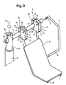
- the boom 2 which will be explained in detail later with reference to FIG. 3, consists of the horizontal support arm 6, the vertical support rails 7, 8 for receiving the bath seat 3, the connecting blocks 9, 10 between the horizontal support arm 6 and vertical support rails 7, 8 as well as a rotatable and foldable handle 11.
- the horizontal support arm 6 is detachably fastened at one end to the piston rod 13 via the clamp screw connection 12, whereby the boom 2 can be raised and lowered and rotated about the cylinder axis 14 in the hydraulic cylinder 15.
- a rotatable and foldable handle 11 is articulated on the horizontal support arm 6, with a handpiece 16 and a guide groove 17 for limiting the rotation.
- a bathtub body 1 can also be used for free-standing installation, and instead of the bathtub seat 3, a lying arrangement can be mounted on the vertical support rails 7, 8.
- the hydraulic unit 18 provided for operating the hydraulic lifting device contains an electric motor 19 and a vane pump 20 and is connected to the hydraulic cylinder 15 via a hydraulic line 21. 2 shows the bathtub seat 3 in the bathing position 4 inside the tub body 1 or in the receiving position 5 outside the tub body 1 with a broken and broken line.
- Each connecting block 9, 10 is divided into two clamping jaws 32, 33 by an incision 31 running parallel with a pair of opposing cuboid boundary surfaces 25, 26, 27, 28, 29, 30 in such a way that the recess 31 intersects at least three cuboid boundary surfaces, two of which are A. and B run parallel to each other.
- the jaws 32, 33 are held together at their free ends 36 via the compression fitting 46 and rigidly connected to one another at their fixed ends 37 by the web 38.
- the clamping jaws 32, 33 can also be connected by a hinge that can be swung out against one another.
- the inner surfaces 39, 40 of the clamping jaws 32, 33 together enclose a clamping bore 41 whose axis 42 lies in the incision plane 43 and stands at right angles on the cuboid boundary surfaces 25, 26, which are labeled A and B for better differentiation.
- the clamping screw connection 46 is tightened, the inner surfaces 39, 40 are pressed against the horizontal support arm 6 on all sides, and this is thereby connected to the connecting blocks 9, 10 in a force-fitting manner.
- the support rails 7, 8 are guided in holding bores 44 running at right angles to the clamping bore 41 and parallel to the incision plane 43, secured therein with locking pins 45 and thereby connected in a form-fitting manner to the connecting blocks 9, 10.
- connection can also be made non-positively by means of a compression fitting.
- the horizontal support arm 6 is by means of the clamping screw connection 12 at the upper end of the Piston rod 13 attached and thus raised and lowered along the cylinder axis 14 and rotatable about the same in the hydraulic cylinder 15.
- a rotatable and foldable handle 11 is attached with a handpiece 16 and guide groove 17 as a stop to limit the angle of rotation.
- FIGS. 1, 2 and 3 To explain the functioning of the boom 2 according to the invention, reference is made to FIGS. 1, 2 and 3, and it is assumed here that the boom 2 must be adapted to a newly installed, narrower tub body 1 and the treatment or care position should be set higher for ergonomic reasons be.
- a narrower seat shell 48 is initially to be mounted on the vertical support rails 7, 8.
- the clamping screw connections 46 are loosened and the cuboid connecting blocks 9, 10 are displaced relative to one another until the vertical support rails 7, 8 have come so close that the narrower seat shell 48 can be mounted thereon.
- the bathtub seat 3 is transferred to the bathtub 47 and the parallelepiped-shaped connecting blocks 9, 10, which are held at a fixed mutual distance, are moved in synchronism on the horizontal support arm 6 until the seat shell 48 assumes the desired position between the long sides of the bathtub in the transverse direction of the bathtub.
- the horizontal support arm 6 in the piston rod 13 can be displaced horizontally by loosening the clamping screw connection 12, resulting in an additional possibility of variation in the transverse direction of the tub.
- a first coarse adjustment is carried out by means of differently shaped vertical support rails 7, 8.
- a second fine adjustment is achieved in that the vertical support rails 7, 8 in the holding holes 44 of the front or rear clamping jaws 32 or 33 of the connecting blocks 9, 10 are guided.
- the inclination of the seat shell 48 with respect to the vertical can be changed such that the seat back with the associated narrow side of the bathtub runs approximately parallel.
- these settings are fixed by tightening the compression fittings 12 and 46.
- the nursing staff When treating patients, the nursing staff must be given the opportunity to take an ergonomically optimal working position.
- its height adjustment is also important. This is ensured in two ways in the boom 2 according to the invention.
- the bath seat 3 can be moved by moving the vertical support rails 7, 8 in the Holding holes 44 can also be adjusted in height relative to the boom.
- the bathtub seat 3 In order to transfer a patient into the bathtub 47, the bathtub seat 3 is brought into the receiving position 5 outside the bathtub body 1, where the patient can be placed on the seat shell 48 safely and comfortably. The seat and patient can then be raised by means of the hydraulics so far over the edge flange 49 of the tub body 1 until an unimpeded pivoting into the area above the bathtub 47 is possible.
- the bath seat 3 automatically lowers into the lower end position in the bath body 1, which, due to the height adjustment of the vertical support rails 7, 8 in the holding bores 44, also represents the therapeutically and ergonomically correct bathing position 4.
- the return from the bathing position 4 to the receiving position 5 takes place in an analogous manner. Both displacements take place safely since the patient is secured against falling in particular by the handle 11.
Landscapes
- Health & Medical Sciences (AREA)
- Nursing (AREA)
- Life Sciences & Earth Sciences (AREA)
- Animal Behavior & Ethology (AREA)
- General Health & Medical Sciences (AREA)
- Public Health (AREA)
- Veterinary Medicine (AREA)
- Devices For Medical Bathing And Washing (AREA)
- Invalid Beds And Related Equipment (AREA)
- Motorcycle And Bicycle Frame (AREA)
Abstract
Description
Ausleger für heb- und drehbare Sitz- und Liegeanordnungen, wie Badewannensitze und dergleichen,.bestehend aus einem, an einer Hebe- und Drehvorrichtung befestigten horizontalen Tragarm, der einerends mittels einer Klemmverschraubung an einer Kolbenstange befestigt is, und an dem mindestens zwei Stützschienen zur Aufnahme von Stützmitteln, wie Sitz- und Liegeschalen befestigt sind.Boom for lifting and rotating seat and lying arrangements, such as bath seats and the like,. Consisting of a horizontal support arm attached to a lifting and rotating device, which is attached at one end to a piston rod by means of a clamp screw connection, and on which at least two support rails for receiving of support means, such as seat and lying shells, are attached.
Solche heb- und senkbare, um eine vertikale Achse drehbare Sitz- und Liegeanordnungen dienen dem Transport und der Lagerung von Kranken und Invaliden und werden allgemein in Einrichtungen zur Erleichterung der Krankenpflege eingesetzt. Bei Badeeinrichtungen ermöglichen sie das sichere und bequeme Überführen von Patienten in und aus Badewannen, welche an die ergonomischen Bedürfnisse des Bedienungs- und Pflegepersonals angepasst sind und deshalb von behinderten Personen nicht ohne fremde Hilfe benützt werden können. Solche Badewannen weisen unterschiedliche Breiten und Höhen auf und unterscheiden sich zudem in der Anschrägung ihrer kopfseitigen Schmalseiten.Such lifting and lowering, rotatable about a vertical axis seating and lying arrangements are used for the transport and storage of sick and disabled and are generally used in facilities to facilitate nursing. In bathing facilities, they enable the safe and comfortable transfer of patients into and out of bathtubs, which are adapted to the ergonomic needs of operating and care personnel and therefore cannot be used by disabled people without outside help. Such bathtubs have different widths and heights and also differ in the bevelling of their narrow ends on the head side.
Es sind bereits Sitz-Überführungseinrichtungen gemäss dem Oberbegriff des Patentanspruches 1 bekannt, bei denen ein horizontaler Tragarm vorgesehen ist, der einerends an einer Hebe- und Drehvorrichtung befestigt ist und an dem vertikale Stützschienen zur Aufnahme von Stützmitteln wie Sitz- und Liegeschalen befestigt sind.There are already known seat transfer devices according to the preamble of
So ist z. B. in der US-A-4 075 719 eine Sitz- Überführungseinrichtung beschrieben, mit der Sitz- und Liegeanordnungen wie z. B. ein Rollstuhl, in einer kombinierten Vertikal- und Schwenkbewegung entlang einer Schraubenlinie zwischen zwei Endstellungen hin und her bewegt werden können. Es betrifft dies insbesondere die Überführung von Invaliden in und aus Badewannen oder - mitsamt dem Rollstuhl - in und aus Verkehrsmitteln. Hiezu ist ein rohrförmiger horizontaler Tragarm mittels einer Klemmverschraubung am vertikal ausfahrenden Zylinder einer hydraulischen Kolben-Zylinder-Einheit befestigt und mit zwei Stützschienen zur Aufnahme einer Sitzschale oder eines Rollstuhles versehen. Zur Verbindung der Stützschienen mit dem horizontalen Tragarm ist letzterer mit Haltebohrungen versehen, in welchen die Stützschienen befestigt sind. Im weitem sind der nach oben ausfahrende vertikal bewegliche Zylinder und der stationäre Kolben über einen Führungsschlitz und einen darin geführten Nocken so untereinander zwanggeführt, dass bei deren Relativbewegung in Längsrichtung immer auch eine gegenseitige Verdrehung um die gemeinsame Längsachse erfolgt, woraus sich die vorgenannte schraubenförmige Bewegungsform ergibt.So z. B. in US-A-4 075 719 describes a seat transfer device with the seat and reclining arrangements such. B. a wheelchair, can be moved back and forth in a combined vertical and pivoting movement along a helix between two end positions. This applies in particular to the transfer of invalids into and out of bathtubs or - together with the wheelchair - into and out of transport. For this purpose, a tubular, horizontal support arm is attached to the vertically extending cylinder of a hydraulic piston-cylinder unit by means of a compression fitting and provided with two support rails for receiving a seat shell or a wheelchair. To connect the support rails to the horizontal support arm, the latter is provided with holding holes in which the support rails are fastened. In addition, the vertically movable cylinder and the stationary piston extend upwards via a guide slot and a cam guided therein so that their relative movement in the longitudinal direction always results in a mutual rotation about the common longitudinal axis, which results in the aforementioned helical form of movement .
Solche Sitz-Überführungseinrichtungen sind aufwendig im Aufbau und beinhalten die bekannten Nachteile massgeschneiderter Einzelanfertigungen. Ein grundsätzlicher Nachteil besteht darin, dass der Abstand des Sitzes zur Kolben-Zylinder-Einheit, konstruktionsbedingt, unveränderlich ist. Dies führt dazu, dass beim Einsatz einer solchen Sitz- Überführungseinrichtung in einem Waschraum der Abstand zwischen der Kolben-Zylinder-Einheit und der Badewanne sowohl in Badewannenlängs- wie in Badewannenquerrichtung sehr genau eingehalten werden muss. Für jede Anlage ist deshalb eine detaillierte Massaufnahme notwendig, wozu qualifiziertes, mit der Anlage vertrautes Personal erforderlich ist. Trotz dieses beträchtlichen Aufwandes lässt sich aber die gegenseitige Abstimmung von Sitz-Uberführungseinrichtung und Badewanne oft nicht in ausreichendem Masse gewährleisten. Zum einen ist mit Ungenauigkeiten bei der Massaufnahme zu rechnen, die später nicht korrigiert werden können, da jede Sitz- Überführungseinrichtung eine starre und unlösbare Einheit bildet. Aber auch bei einwandfreier Massaufnahme hat sich ein genaues Einhalten der Abstände in der Praxis als schwierig erwiesen. Dies deshalb, weil mit gebräulichen Verankerungsmassnahmen, wie eingiessen von Bolzen in Beton, nur eine grobe gegenseitige Ausrichtung zwischen horizontalem Tragarm und Badewanne erzielt werden kann. Bei der bekannten Vorrichtung nach US-A-4 075 719 ist deshalb die Positionierung des Sitzes relativ zur Badewanne zumindest seitlich, meist aber auch in Längsrichtung, oft nicht korrekt. Es bleibt dann nichts anderes übrig, als den horizontalen Tragarm und meist auch die Kolben-Zylinder-Einheit durch eine Neukonstruktion zu ersetzen. Ein zusätzlicher Nachteil muss darin gesehen werden, dass anlagebezogene Konstruktionselemente verschiedenster Abmessungen verwendet werden. Der Einsatz von in grossen Serien gefertigten Einzelteilen, die für einen weiten Bereich von Anlagen in Form von gleichartigen Normteilen eingesetzt werden können, ist allgemein nicht möglich. Dies erschwert die Ersatzteilhaltung. Weiter hat sich bei solchen Sitz-Überführungseinrichtungen als nachteilig erwiesen, dass sie hinsichtlich einer bestimmten Badewanne massgeschneidert sind, d.h. auf deren Höhe, Breite und Anordnung im Waschraum abgestimmt sind. Es ist deshalb nicht möglich, sie beim Auswechseln von Badewannen oder bei sonstigen baulichen Veränderungen an die neuen Gegebenheiten anzupassen.Such seat transfer devices are complex in construction and contain the known disadvantages of custom-made items. A fundamental disadvantage is that the distance between the seat and the piston-cylinder unit cannot be changed by design. This means that when using such a seat transfer device in a washroom, the distance between the piston-cylinder unit and the bathtub must be observed very precisely, both in the longitudinal and transverse directions of the bathtub. A detailed measurement is therefore required for each system, which requires qualified personnel who are familiar with the system. Despite this considerable effort, the mutual coordination of seat transfer device and bathtub can often not be guaranteed to a sufficient extent. On the one hand, inaccuracies in the measurement are to be expected, which cannot be corrected later, since each seat transfer device forms a rigid and non-detachable unit. But even with perfect measurements, keeping the distances exactly in practice has proven difficult. This is because with common anchoring measures, such as pouring bolts into concrete, only a rough mutual alignment between the horizontal support arm and the bathtub can be achieved. In the known device according to US-A-4 075 719, the positioning of the seat relative to the bathtub is therefore often incorrect, at least laterally, but usually also in the longitudinal direction. Then there is nothing left but to replace the horizontal support arm and usually also the piston-cylinder unit with a new design. An additional disadvantage must be seen in the fact that system-related construction elements of various dimensions are used. The use of individual parts manufactured in large series, which can be used for a wide range of systems in the form of similar standard parts, is generally not possible. This makes it difficult to keep spare parts. Furthermore, such seat transfer devices have proven disadvantageous in that they are tailor-made with regard to a specific bathtub, i.e. to their height, width and arrangement in the washroom. It is therefore not possible to adapt them to the new conditions when changing bathtubs or other structural changes.
Hier will die Erfindung Abhilfe schaffen. Die Erfindung, wie sie in den Ansprüchen gekennzeichnet ist, löst die Aufgabe, einen Ausleger für heb- und drehbare Sitz- und Liegeanordnungen, wie Badewannensitze, zu schaffen, der sich bei der Montage auf die Abmessungen unterschiedlicher apparativer und baulicher Gegebenheiten einstellen lässt. Dies soll vorgängige Massaufnahmen weitgehend überflüssig machen und dadurch die Auftragsbearbeitung erleichtern. Die Neuerung bezweckt ferner die Schaffung eines Auslegers, der aus wenigen in grossen Serien gefertigten Normteilen aufgebaut werden kann und bei dem die Lagerhaltung vereinfacht sowie die Herstellung verbilligt ist. Diese Aufgabe wird erfindungsgemäss mit den Mitteln gelöst, wie sie in der Fassung des unabhängigen Anspruches gekennzeichnet sind. Vorteilhafte Weiterbildungen sind in den abhängigen Ansprüchen angegeben.The invention seeks to remedy this. The invention, as characterized in the claims, solves the problem of creating a boom for lifting and rotating seating and lying arrangements, such as bathtub seats, which can be adjusted to the dimensions of different apparatus and structural conditions during assembly. This is to make previous measurements largely superfluous and thereby Make order processing easier. The innovation also aims to create a cantilever that can be built from a few standard parts that are manufactured in large series and that simplifies warehousing and makes production cheaper. This object is achieved according to the invention with the means as characterized in the version of the independent claim. Advantageous further developments are specified in the dependent claims.
Durch diese Mittel ist nicht nur die der Erfindung zugrunde liegende Aufgabe vorteilhaft gelöst, sondern es wird darüber hinaus ein Ausleger geschaffen, der folgende Vorteile bietet:These means not only advantageously achieve the object on which the invention is based, but also create an extension arm which offers the following advantages:
Da eine lösbare und einstellbare Konstruktion vorliegt, kann der Ausleger auch nach der Montage sehr einfach und rasch geänderten Verhältnissen angepasst werden, wie sie sich aus apparativen und baulichen Umstellungen, geänderten Pflege- und Behandlungsmethoden sowie wechselnden ergonomischen Anforderungen des Pflege- und Bedienungspersonales ergeben. Ein derart ausgebildeter Ausleger besitzt eine Flexibilität in der Anwendung, wie sie mit geschweissten, massgeschneiderten Konstruktionen nicht erreicht werden kann.Since there is a detachable and adjustable construction, the boom can be easily and quickly adapted to changing conditions, such as those resulting from changes in equipment and construction, changed care and treatment methods, and changing ergonomic requirements for care and operating personnel. A boom designed in this way has flexibility in use that cannot be achieved with welded, tailor-made constructions.
Im weitern sind die wesentlichen Elemente des erfindungsgemässen Aufbaukonzeptes, nämlich der horizontale Tragarm, die Verbindungsstücke sowie die Klemmverschraubungen funktions- und nicht anlagebezogen, also unabhängig von einer Anlage in der gleichen Ausführung immer wieder einsetzbar. Die Ausrichtung eines Auslegers, auf den einzelnen Anwendungsfall erfolgt durch dimensionsmässiges Einstellen während der Montage. Hinsichtlich der Konstruktionselemente wie der Verbindungstechnik kann deshalb von einem bausteinartigen Aufbau gesprochen werden. Für eine grosse Variantenzahl von Anlagen können die gleichen in Normgrössen serienmässig hergestellten Einzelteile verwendet werden. Daraus ergibt sich der Vorteil einer einfachen Fertigung sowie einer unkomplizierten Disposition des Materialbedarfs. Auch sind die bausteinartigen Einzelteile nach der Erfindung so ausgebildet, dass sie sich an Ort und Stelle leicht montieren und auch wieder leicht demontieren lassen und ein verhältnismässig geringes Gewicht aufweisen. Der erfindungsgemässe Ausleger eignet sich deshalb vortrefflich zum Zusammenbau an Ort und Stelle, wo wegen baulicher oder anderer Erschwernisse oft unter schwierigen Bedingungen gearbeitet werden muss. Allfällige Unzulänglichkeiten in der Arbeitsausführung können später leicht korrigiert werden. Darüber hinaus hat sich als vorteilhaft erwiesen, dass wegen der leichten Auswechselbarkeit der Einzelteile die Instandhaltung des Auslegers sowie die entsprechende Instruktion des Wartungspersonals stark vereinfacht ist. Es ist offensichtlich, dass die mit der Erfindung erzielten Verbesserungen, wie leichte Anpassbarkeit nach der Montage, bausteinartiger Aufbau, haltung auch wirtschaftliche Vorteile bieten: die Herstellung der Ausleger wird verbilligt, die Kosten für deren Montage und Unterhalt merklich gesenkt und so allgemein eine kostengünstige Lösung erzielt.Furthermore, the essential elements of the construction concept according to the invention, namely the horizontal support arm, the connecting pieces and the compression fittings are function-related and not system-related, that is, they can be used again and again regardless of a system in the same design. The alignment of a boom to the individual application is done by dimensional adjustment during assembly. With regard to the construction elements such as the connection technology, one can therefore speak of a modular structure. For a large number of variants of systems, the same individual parts that are standardly produced in standard sizes can be used. This results in the advantage of simple production and an uncomplicated disposition of the material requirements. The modular parts according to the invention are designed so that they are easy to assemble on site and also easy to dismantle and have a relatively low weight. The boom according to the invention is therefore excellently suitable for assembly on the spot where work often has to be carried out under difficult conditions due to structural or other difficulties. Any shortcomings in the execution of the work can be easily corrected later. In addition, it has proven to be advantageous that because of the easy interchangeability of the individual parts, the maintenance of the boom and the corresponding instructions for the maintenance personnel are greatly simplified. It is obvious that the improvements achieved with the invention, such as easy adaptability after assembly, modular structure, and posture, also offer economic advantages: the manufacture of the brackets is cheaper, the costs for their assembly and maintenance are noticeably reduced, and in general a cost-effective solution achieved.
Die Erfindung wird nachstehend in ihrer Anwendung als Tragkonstruktion für einen Badewannensitz beschrieben, jedoch ist das hier zugrunde liegende Prinzip entsprechend auch für andere Sitz- und Liegeanordnungen verwendbar.The invention is described below in its application as a supporting structure for a bathtub seat, but the principle on which it is based can also be used correspondingly for other seating and lying arrangements.
In der, lediglich einen Ausführungsweg darstellenden, Zeichnung zeigt:
- Fig. 1 in perspektivischer Sicht eine Badeeinrichtung mit dem erfindungsgemässen Ausleger, wobei die Sitzanordnung in Bade- bzw. Pflegeposition dargestellt ist.
- Fig. 2 im Grundriss eine Badeeinrichtung mit dem erfindungsgemässen Ausleger, wobei die Sitzanordnung sowohl in Aufnahme wie in Bade- bzw. Pflegeposition dargestellt ist,
- Fig. 3 in perspektivischer Sicht den erfindungsgemässen Ausleger im Zusammenbau mit der zugehörigen hydraulischen Hebe- und Schwenkvorrichtung.
- Fig. 1 in perspective view of a bathing device with the arm according to the invention, the seating arrangement being shown in the bathing or care position.
- 2 is a floor plan of a bathing facility with the arm according to the invention, the seating arrangement being shown both in the receptacle and in the bathing or care position,
- Fig. 3 in perspective view of the boom according to the invention in the assembly with the associated hydraulic lifting and pivoting device.
In Fig. 1 ist mit 1 ein Wannenkörper für Einbauanordnung bezeichnet, in dem sich ein vom Ausleger 2 gehaltener Badewannensitz 3 in Bade- bzw. Pflegestellung 4 befindet. Der Ausleger 2, der mit Bezug auf Fig. 3 später eingehend erläutert wird, besteht aus dem horizontalen Tragarm 6, den vertikalen Stützschienen 7, 8 zur Aufnahme des Badewannensitzes 3, den Verbindungsblöcken 9, 10 zwischen horizontalem Tragarm 6 und vertikalen Stützschienen 7, 8 sowie einem dreh-und wegklappbaren Haltegriff 11. Über die Klemmverschraubung 12 ist der horizontale Tragarm 6 einerends lösbar an der Kolbenstange 13 befestigt, wodurch der Ausleger 2 heb- und senkbar sowie um die Zylinderachse 14 drehbar im Hydraulikzylinder 15 gelagert ist. Anderends ist am horizontalen Tragarm 6 ein dreh- und wegklappbarer Haltegriff 11 angelenkt, mit Handstück 16 und Führungsnut 17 zur Begrenzung der Ausdrehung. Selbstverständlich kann auch ein Wannenkörper 1 für Freiaufstellung verwendet werden, und anstelle des Badewannensitzes 3 eine Liegeanordnung auf den vertikalen Stützschienen 7, 8 montiert sein. Das zum Betrieb der hydraulischen Hebevorrichtung vorgesehene hydraulische Aggregat 18 enthält einen Elektromotor 19 sowie eine Flügelpumpe 20 und ist über eine Hydraulikleitung 21 mit dem Hydraulikzylinder 15 verbunden. Fig. 2 zeigt mit ausgezogenem und unterbrochenem Strich den Badewannensitz 3 in Badestellung 4 innerhalb des Wannenkörpers 1 bzw. in Aufnahmestellung 5 ausserhalb des Wannenkörpers 1. Im Rahmen der baulichen Gegebenheiten sind aber auch alle anderen Positionen des Badewannensitzes 3 möglich, die sich auf einer durch den Kreisbogen 23 um die Zylinderachse 14 und den Kolbenhub 24 bestimmten Zylinderfläche befinden. Und weil der Badewannensitz 3 über die quaderförmigen Verbindungsblöcke 9,10 verschiebbar am horizontalen Tragarm 6 befestigt ist, gilt dies noch zusätzlich für alle Positionen innerhalb dieser Zylinderfläche. Die konstruktive Ausgestaltung sowie das Aufbaukonzept, beides wesentliche Merkmale der vorliegenden Erfindung, werden im folgenden anhand der Fig. 3 näher erläutert: Die beiden die Sitzschale 48 tragenden vertikalen Stützschienen 7, 8 sind mittels quaderförmiger Verbindungsblöcke 9, 10 lösbar und einstellbar mit dem horizontalen Tragarm 6 verbunden. Dabei ist jeder Verbindungsblock 9, 10 durch einen mit einem Paar gegenüberliegender Quaderbegrenzungsflächen 25, 26, 27, 28, 29, 30 parallel verlaufenden Einschnitt 31 in zwei Klemmbacken 32, 33 so aufgeteilt, dass der Einschnitt 31 mindestens drei Quaderbegrenzungsflächen schneidet, wovon zwei A und B parallel zueinander verlaufen. Die Klemmbacken 32,33 sind an ihren freien Enden 36 über die Klemmverschraubung 46 zusammengehalten und an ihren festen Enden 37 durch den Steg 38 starr miteinander verbunden. Anstelle des Steges 38 können die Klemmbacken 32, 33 auch durch ein Scharnier, gegeneinander ausschwenkbar, verbunden sein. Die Innenflächen 39, 40 der Klemmbacken 32, 33 umschliessen zusammen eine Klemmbohrung 41 deren Achse 42 in der Einschnittebene 43 liegt und rechtwinklig auf den Quaderbegrenzungsflächen 25, 26 steht, die zur besseren Unterscheidung mit A bzw. B bezeichnet sind. Bei Anziehen der Klemmverschraubung 46 werden die Innenflächen 39, 40 allseitig gegen den horizontalen Tragarm 6 gepresst und dieser dadurch kraftschlüssig mit den Verbindungsblöcken 9, 10 verbunden. Die Stützschienen 7, 8 sind in rechtwinklig zur Klemmbohrung 41 und parallel zur Einschnittebene 43 verlaufenden Haltebohrungen 44 geführt, darin mit Arretierstiften 45 gesichert und dadurch formschlüssig mit den Verbindungsblöcken 9, 10 verbunden. Selbstverständlich kann auch hier die Verbindung kraftschlüssig durch eine Klemmverschraubung erfolgen. Als weitere Variante ist es möglich, alternativ oder zusätzlich auch in den Klemmbacken 33 der Verbindungsblöcke 9,10 je eine Haltebohrung 44 vorzusehen, zur Aufnahme der gleichen oder zusätzlicher Stützschienen 7, 8. Der horizontale Tragarm 6 ist mittels der Klemmverschraubung 12 am oberen Ende der Kolbenstange 13 befestigt und damit entlang der Zylinderachse 14 heb- und senkbar und um dieselbe drehbar im Hyraulikzylinder 15 gelagert. Am anderen Ende des horizontalen Tragarmes 6 ist ein dreh- und wegklappbarer Haltegriff 11 angebracht mit Handstück 16 und Führungsnut 17 als Anschlag zur Begrenzung des Ausdrehwinkels.In Fig. 1, 1 denotes a tub body for installation arrangement, in which a
Zur Erläuterung der Funktionsweise des erfindungsgemässen Auslegers 2 sei auf die Figuren 1, 2 und 3 verwiesen, und dabei angenommen, dass der Ausleger 2 an einen neu aufgestellten, schmäleren Wannenkörper 1 angepasst werden müsse und die Behandlungs- bzw. Pflegestellung aus ergonomischen Gründen höher einzustellen sei.To explain the functioning of the
Wegen des schmäleren Wannenkörpers 1 ist vorerst eine schmälere Sitzschale 48 auf den vertikalen Stützschienen 7, 8 zu montieren. Hiezu werden die Klemmverschraubungen 46 gelöst und die quaderförmigen Verbindungsblöcke 9, 10 gegeneinander verschoben, bis sich die vertikalen Stützschienen 7, 8 so weit angenähert haben, dass darauf die schmälere Sitzschale 48 montiert werden kann. Als nächstes wird der Badewannensitz 3 in die Badewanne 47 überführt und die in festem gegenseitigen Abstand gehaltenen quaderförmigen Verbindungsblöcke 9, 10 im Gleichlauf so auf dem horizontalen Tragarm 6 verschoben, bis die Sitzschale 48 in Badewannenquerrichtung die gewünschte Lage zwischen den Badewannenlängsseiten einnimmt. Sollte die Verschiebung der Verbindungblöcke 9, 10 entlang dem horizontalen Tragarm 6 nicht ausreichen, um die Sitzschale 48 quer im Wannenkörper 1 zu positionieren, kann durch Lösen der Klemmverschraubung 12 der horizontale Tragarm 6 in der Kolbenstange 13 horizontal verschoben werden, woraus sich eine zusätzliche Variationsmöglichkeit in Wannenquerrichtung ergibt. Für die Positionierung der Sitzschale 48 in Badewannenlängsrichtung erfolgt ein erster grobstufiger Abgleich durch verschieden geformte vertikale Stützschienen 7, 8. Ein zweiter feinstufiger Abgleich wird dadurch erzielt, dass die vertikalen Stützschienen 7, 8 in den Haltebohrungen 44 der vorderen oder der hinteren Klemmbacken 32 bzw. 33 der Verbindungsblöcke 9,10 geführt sind. Im weitern kann durch Drehen der quaderförmigen Verbindungsblöcke 9, 10 um den horizontalen Tragarm 6 die Neigung der Sitzschale 48 gegenüber der Vertikalen so geändert werden, dass die Sitzrücklehne mit der zugehörigen Badewannenschmalseite in etwa parallel verläuft. Nachdem die Sitzschale 48 in Quer- und in Längsrichtung sowie hinsichtlich ihrer Neigung an den neuen Wannenkörper 1 angepasst ist, werden diese Einstellungen durch Anziehen der Klemmverschraubungen 12 und 46 fixiert. Bei der Behandlung von Patienten muss dem Pflegepersonal die Möglichkeit gegeben werden, eine ergonomisch optimale Arbeitsstellung einzunehmen. In diesem Zusammenhang ist neben der vorgenannten Verschiebbarkeit des Badewannensitzes 3 quer, längs und schräg zur Badewanne 47 auch dessen Höhenverstellung von Bedeutung. Dies ist beim erfindungsgemässen Ausleger 2 in zweifacher Weise gewährleistet. Neben der hydraulischen Höhenverstellung des Auslegers 2 kann der Badewannensitz 3 durch Verschieben der vertikalen Stützschienen 7, 8 in den Haltebohrungen 44 auch relativ zum Ausleger in der Höhe verstellt werden. Zur Überführung eines Patienten in die Badewanne 47 wird der Badewannensitz 3 in die Aufnahmestellung 5 ausserhalb des Wannenkörpers 1 gebracht, wo der Patient sicher und bequem auf der Sitzschale 48 plaziert werden kann. Sitz und Patient können alsdann mittels der Hydraulik so weit über den Randflansch 49 des Wannenkörpers 1 angehoben werden, bis ein ungehindertes Einschwenken in den Bereich über der Badewanne 47 möglich ist. Bei Entlastung der Hydraulik senkt sich der Badewannensitz 3 automatisch in die untere Endstellung im Wannenkörper 1, die aufgrund der Höheneinstellung der vertikalen Stützschienen 7, 8 in den Haltebohrungen 44 auch die therapeutisch und ergonomisch richtige Badestellung 4 darstellt. Die Rückführung von der Badestellung 4 in die Aufnahmestellung 5 wickelt sich in analoger Weise ab. Beide Verschiebungen erfolgen gefahrlos, da der Patient durch den Haltegriff 11 insbesondere gegen Herabfallen gesichert ist.Because of the
Claims (4)
Priority Applications (1)
| Application Number | Priority Date | Filing Date | Title |
|---|---|---|---|
| AT84100653T ATE32557T1 (en) | 1983-03-03 | 1984-01-23 | EXTENSIONS FOR LIFTING AND ROTATING SEATING AND LYING ARRANGEMENTS. |
Applications Claiming Priority (2)
| Application Number | Priority Date | Filing Date | Title |
|---|---|---|---|
| CH1154/83 | 1983-03-03 | ||
| CH1154/83A CH659575A5 (en) | 1983-03-03 | 1983-03-03 | CARRYING DEVICE FOR A LIFTING AND ROTATING SEAT OR LAYER ARRANGEMENT. |
Publications (2)
| Publication Number | Publication Date |
|---|---|
| EP0117992A1 EP0117992A1 (en) | 1984-09-12 |
| EP0117992B1 true EP0117992B1 (en) | 1988-02-24 |
Family
ID=4203739
Family Applications (1)
| Application Number | Title | Priority Date | Filing Date |
|---|---|---|---|
| EP84100653A Expired EP0117992B1 (en) | 1983-03-03 | 1984-01-23 | Support for liftable and turnable lying and sitting arrangements |
Country Status (5)
| Country | Link |
|---|---|
| US (1) | US4569091A (en) |
| EP (1) | EP0117992B1 (en) |
| AT (1) | ATE32557T1 (en) |
| CH (1) | CH659575A5 (en) |
| DE (1) | DE3469406D1 (en) |
Families Citing this family (14)
| Publication number | Priority date | Publication date | Assignee | Title |
|---|---|---|---|---|
| GB2196247B (en) * | 1986-10-17 | 1990-05-16 | Impro Ltd | Bathing device |
| DE3821192A1 (en) * | 1988-06-23 | 1989-12-28 | Peter Schmidt | BACKREST FOR SEAT OR LYING PANELS |
| CH686658A5 (en) * | 1992-11-20 | 1996-05-31 | Kurt Brandenberger | Transport means for the bath and shower operation, in particular Disabled people. |
| US5329651A (en) * | 1993-04-23 | 1994-07-19 | Fiat Products Ltd. | Bathing apparatus for the infirm |
| US5367721A (en) * | 1993-10-12 | 1994-11-29 | Biocare Laboratories, Inc. | Lift apparatus and method for transporting a passenger into and out of a swimming pool |
| US5960488A (en) * | 1995-01-19 | 1999-10-05 | Morris; Edward J. | Lift chair for a mechanical lift |
| DE29518469U1 (en) * | 1995-11-21 | 1997-03-20 | Wöhler, Horst, 51491 Overath | Bath and shower device |
| US20040231043A1 (en) * | 2000-04-14 | 2004-11-25 | Pop-In Pop-Out, Inc. | Bath lifting system |
| US20040098801A1 (en) * | 2000-04-14 | 2004-05-27 | Pop-In Pop-Out, Inc | Bath lifting system |
| US6643861B2 (en) | 2000-04-14 | 2003-11-11 | Freedom Bath, Inc. | Bath lifting system |
| US6397409B1 (en) | 2000-04-14 | 2002-06-04 | Freedom Bath, Inc. | Bath lifting system |
| US6351860B1 (en) * | 2001-03-27 | 2002-03-05 | Richard C. Schaffer | Bathtub chair lift |
| KR101755579B1 (en) | 2017-04-27 | 2017-07-10 | 강익하 | Sink with bath articles for baby |
| US11318058B2 (en) * | 2019-04-10 | 2022-05-03 | Malcolm Berg | Lift for water entry/exit and methods of manufacture and use thereof |
Family Cites Families (12)
| Publication number | Priority date | Publication date | Assignee | Title |
|---|---|---|---|---|
| US870910A (en) * | 1907-03-08 | 1907-11-12 | William Splittgerber | Handle. |
| GB191322962A (en) * | 1913-09-11 | 1914-08-13 | Frank Hornby | Improvements in Couplings or the like Devices for Shafts, Rods, Axles, or the like. |
| FR1068083A (en) * | 1952-09-29 | 1954-06-22 | Constructions Aeronautiques Sudest | Device for the materialization of the precise position of a point in space according to its coordinates and its applications. |
| US2788055A (en) * | 1953-08-13 | 1957-04-09 | Tumas John | Baby bath tub safety device |
| US3371357A (en) * | 1965-05-10 | 1968-03-05 | Centnry Mfg Co | Bath lift |
| US3574364A (en) * | 1969-03-13 | 1971-04-13 | Gilbert Hyde Chick Co | Frame joint |
| US3612042A (en) * | 1970-01-13 | 1971-10-12 | Louis R Fry | Hip exerciser |
| US3945291A (en) * | 1974-10-02 | 1976-03-23 | Zickos William T | Drum construction |
| US4003479A (en) * | 1975-06-04 | 1977-01-18 | Reyer William J | Hoist and transporting apparatus |
| US4075719A (en) * | 1976-09-01 | 1978-02-28 | Sullivan Lawrence J | Chair lift apparatus |
| US4437791A (en) * | 1982-04-02 | 1984-03-20 | Reynolds Graeme E | Clamp for hydraulic hose bundles |
| GB2123285A (en) * | 1982-07-13 | 1984-02-01 | Frederick Alan Fearn | Lifting apparatus |
-
1983
- 1983-03-03 CH CH1154/83A patent/CH659575A5/en not_active IP Right Cessation
-
1984
- 1984-01-23 AT AT84100653T patent/ATE32557T1/en not_active IP Right Cessation
- 1984-01-23 EP EP84100653A patent/EP0117992B1/en not_active Expired
- 1984-01-23 DE DE8484100653T patent/DE3469406D1/en not_active Expired
- 1984-02-21 US US06/581,781 patent/US4569091A/en not_active Expired - Lifetime
Non-Patent Citations (1)
| Title |
|---|
| MECHANISM LINKAGES AND MECHANICAL CONTROLS, By N.P.CHIRONIS, pages 342+345 * |
Also Published As
| Publication number | Publication date |
|---|---|
| CH659575A5 (en) | 1987-02-13 |
| ATE32557T1 (en) | 1988-03-15 |
| US4569091A (en) | 1986-02-11 |
| DE3469406D1 (en) | 1988-03-31 |
| EP0117992A1 (en) | 1984-09-12 |
Similar Documents
| Publication | Publication Date | Title |
|---|---|---|
| EP0117992B1 (en) | Support for liftable and turnable lying and sitting arrangements | |
| DE2625047C3 (en) | ||
| EP0058411A1 (en) | Obstetric examining and delivery chair | |
| DE2512534C2 (en) | ||
| DE3218328A1 (en) | OPERATING TABLE | |
| DE2348349A1 (en) | BATHTUB | |
| DE3112679A1 (en) | Bath tub insert | |
| EP0380621B1 (en) | Bathing aid | |
| DE1261625B (en) | Chair, especially dental chair | |
| DE1263986B (en) | Bathtub combined with a transport device for moving patients and a lifting device | |
| EP2515999A1 (en) | Treatment device using magnetic fields | |
| DE2521362C3 (en) | Auxiliary device for a toilet | |
| EP0400664B1 (en) | Lifting and transporting device for patients | |
| DE4319684C2 (en) | Delivery bed | |
| DE3500313C2 (en) | ||
| DE69113477T2 (en) | SUPPORT DEVICE. | |
| WO2011003808A1 (en) | Bed frame having a virtual back joint | |
| DE2010121A1 (en) | Sickbed | |
| DE2947327A1 (en) | SICK AND PROPERTY CHAIR | |
| DE4009283C2 (en) | ||
| DE1616167B1 (en) | wheelchair | |
| DE4037015C2 (en) | ||
| DE1275725B (en) | Operating table | |
| DE3839742C2 (en) | ||
| DE1566460A1 (en) | Stand device movable on a level floor surface |
Legal Events
| Date | Code | Title | Description |
|---|---|---|---|
| PUAI | Public reference made under article 153(3) epc to a published international application that has entered the european phase |
Free format text: ORIGINAL CODE: 0009012 |
|
| AK | Designated contracting states |
Designated state(s): AT BE DE FR GB IT LU NL SE |
|
| 17P | Request for examination filed |
Effective date: 19841217 |
|
| GRAA | (expected) grant |
Free format text: ORIGINAL CODE: 0009210 |
|
| AK | Designated contracting states |
Kind code of ref document: B1 Designated state(s): AT BE DE FR GB IT LU NL SE |
|
| PG25 | Lapsed in a contracting state [announced via postgrant information from national office to epo] |
Ref country code: IT Free format text: LAPSE BECAUSE OF FAILURE TO SUBMIT A TRANSLATION OF THE DESCRIPTION OR TO PAY THE FEE WITHIN THE PRESCRIBED TIME-LIMIT;WARNING: LAPSES OF ITALIAN PATENTS WITH EFFECTIVE DATE BEFORE 2007 MAY HAVE OCCURRED AT ANY TIME BEFORE 2007. THE CORRECT EFFECTIVE DATE MAY BE DIFFERENT FROM THE ONE RECORDED. Effective date: 19880224 Ref country code: NL Effective date: 19880224 |
|
| REF | Corresponds to: |
Ref document number: 32557 Country of ref document: AT Date of ref document: 19880315 Kind code of ref document: T |
|
| REF | Corresponds to: |
Ref document number: 3469406 Country of ref document: DE Date of ref document: 19880331 |
|
| ET | Fr: translation filed | ||
| NLV1 | Nl: lapsed or annulled due to failure to fulfill the requirements of art. 29p and 29m of the patents act | ||
| GBV | Gb: ep patent (uk) treated as always having been void in accordance with gb section 77(7)/1977 [no translation filed] | ||
| PG25 | Lapsed in a contracting state [announced via postgrant information from national office to epo] |
Ref country code: GB Free format text: LAPSE BECAUSE OF NON-PAYMENT OF DUE FEES Effective date: 19881122 |
|
| PLBE | No opposition filed within time limit |
Free format text: ORIGINAL CODE: 0009261 |
|
| STAA | Information on the status of an ep patent application or granted ep patent |
Free format text: STATUS: NO OPPOSITION FILED WITHIN TIME LIMIT |
|
| 26N | No opposition filed | ||
| EPTA | Lu: last paid annual fee | ||
| EAL | Se: european patent in force in sweden |
Ref document number: 84100653.9 |
|
| PGFP | Annual fee paid to national office [announced via postgrant information from national office to epo] |
Ref country code: SE Payment date: 19971204 Year of fee payment: 15 |
|
| PGFP | Annual fee paid to national office [announced via postgrant information from national office to epo] |
Ref country code: BE Payment date: 19971212 Year of fee payment: 15 |
|
| PGFP | Annual fee paid to national office [announced via postgrant information from national office to epo] |
Ref country code: DE Payment date: 19971219 Year of fee payment: 15 |
|
| PGFP | Annual fee paid to national office [announced via postgrant information from national office to epo] |
Ref country code: AT Payment date: 19971222 Year of fee payment: 15 |
|
| PGFP | Annual fee paid to national office [announced via postgrant information from national office to epo] |
Ref country code: FR Payment date: 19971226 Year of fee payment: 15 |
|
| PGFP | Annual fee paid to national office [announced via postgrant information from national office to epo] |
Ref country code: LU Payment date: 19980128 Year of fee payment: 15 |
|
| PG25 | Lapsed in a contracting state [announced via postgrant information from national office to epo] |
Ref country code: LU Free format text: LAPSE BECAUSE OF NON-PAYMENT OF DUE FEES Effective date: 19990123 Ref country code: AT Free format text: LAPSE BECAUSE OF NON-PAYMENT OF DUE FEES Effective date: 19990123 |
|
| PG25 | Lapsed in a contracting state [announced via postgrant information from national office to epo] |
Ref country code: SE Free format text: LAPSE BECAUSE OF NON-PAYMENT OF DUE FEES Effective date: 19990124 |
|
| PG25 | Lapsed in a contracting state [announced via postgrant information from national office to epo] |
Ref country code: BE Free format text: LAPSE BECAUSE OF NON-PAYMENT OF DUE FEES Effective date: 19990131 |
|
| BERE | Be: lapsed |
Owner name: BRANDENBERGER KURT Effective date: 19990131 |
|
| PG25 | Lapsed in a contracting state [announced via postgrant information from national office to epo] |
Ref country code: FR Free format text: LAPSE BECAUSE OF NON-PAYMENT OF DUE FEES Effective date: 19990930 |
|
| PG25 | Lapsed in a contracting state [announced via postgrant information from national office to epo] |
Ref country code: DE Free format text: LAPSE BECAUSE OF NON-PAYMENT OF DUE FEES Effective date: 19991103 |
|
| REG | Reference to a national code |
Ref country code: FR Ref legal event code: ST |