EP0117985A2 - Method of producing moulds for injection moulding, particularly tools for the injection moulding of plastic materials - Google Patents
Method of producing moulds for injection moulding, particularly tools for the injection moulding of plastic materials Download PDFInfo
- Publication number
- EP0117985A2 EP0117985A2 EP84100577A EP84100577A EP0117985A2 EP 0117985 A2 EP0117985 A2 EP 0117985A2 EP 84100577 A EP84100577 A EP 84100577A EP 84100577 A EP84100577 A EP 84100577A EP 0117985 A2 EP0117985 A2 EP 0117985A2
- Authority
- EP
- European Patent Office
- Prior art keywords
- backfill
- metal
- stainless steel
- layer
- shell
- Prior art date
- Legal status (The legal status is an assumption and is not a legal conclusion. Google has not performed a legal analysis and makes no representation as to the accuracy of the status listed.)
- Granted
Links
Images


Classifications
-
- B—PERFORMING OPERATIONS; TRANSPORTING
- B29—WORKING OF PLASTICS; WORKING OF SUBSTANCES IN A PLASTIC STATE IN GENERAL
- B29C—SHAPING OR JOINING OF PLASTICS; SHAPING OF MATERIAL IN A PLASTIC STATE, NOT OTHERWISE PROVIDED FOR; AFTER-TREATMENT OF THE SHAPED PRODUCTS, e.g. REPAIRING
- B29C33/00—Moulds or cores; Details thereof or accessories therefor
- B29C33/38—Moulds or cores; Details thereof or accessories therefor characterised by the material or the manufacturing process
-
- B—PERFORMING OPERATIONS; TRANSPORTING
- B29—WORKING OF PLASTICS; WORKING OF SUBSTANCES IN A PLASTIC STATE IN GENERAL
- B29C—SHAPING OR JOINING OF PLASTICS; SHAPING OF MATERIAL IN A PLASTIC STATE, NOT OTHERWISE PROVIDED FOR; AFTER-TREATMENT OF THE SHAPED PRODUCTS, e.g. REPAIRING
- B29C33/00—Moulds or cores; Details thereof or accessories therefor
- B29C33/56—Coatings, e.g. enameled or galvanised; Releasing, lubricating or separating agents
- B29C33/565—Consisting of shell-like structures supported by backing material
-
- B—PERFORMING OPERATIONS; TRANSPORTING
- B29—WORKING OF PLASTICS; WORKING OF SUBSTANCES IN A PLASTIC STATE IN GENERAL
- B29C—SHAPING OR JOINING OF PLASTICS; SHAPING OF MATERIAL IN A PLASTIC STATE, NOT OTHERWISE PROVIDED FOR; AFTER-TREATMENT OF THE SHAPED PRODUCTS, e.g. REPAIRING
- B29C33/00—Moulds or cores; Details thereof or accessories therefor
- B29C33/56—Coatings, e.g. enameled or galvanised; Releasing, lubricating or separating agents
- B29C33/60—Releasing, lubricating or separating agents
-
- B—PERFORMING OPERATIONS; TRANSPORTING
- B29—WORKING OF PLASTICS; WORKING OF SUBSTANCES IN A PLASTIC STATE IN GENERAL
- B29C—SHAPING OR JOINING OF PLASTICS; SHAPING OF MATERIAL IN A PLASTIC STATE, NOT OTHERWISE PROVIDED FOR; AFTER-TREATMENT OF THE SHAPED PRODUCTS, e.g. REPAIRING
- B29C45/00—Injection moulding, i.e. forcing the required volume of moulding material through a nozzle into a closed mould; Apparatus therefor
- B29C45/17—Component parts, details or accessories; Auxiliary operations
- B29C45/26—Moulds
- B29C45/37—Mould cavity walls, i.e. the inner surface forming the mould cavity, e.g. linings
Landscapes
- Engineering & Computer Science (AREA)
- Mechanical Engineering (AREA)
- Manufacturing & Machinery (AREA)
- Moulds For Moulding Plastics Or The Like (AREA)
- Processing And Handling Of Plastics And Other Materials For Molding In General (AREA)
- Mechanical Treatment Of Semiconductor (AREA)
- Processing Of Stones Or Stones Resemblance Materials (AREA)
- Crystals, And After-Treatments Of Crystals (AREA)
- Coating By Spraying Or Casting (AREA)
- Molds, Cores, And Manufacturing Methods Thereof (AREA)
Abstract
Description
Die vorliegende Erfindung betrifft ein Verfahren zur Erstellung von Formen für das Spritzgießen, insbesonders von Werkzeugen für das Spritzgießen von Kunststoff. Bisher mußten hochwertige Werkzeuge spanabhebend aus Edelstahlblocken herausgearbeitet werden; die Qualität und Maßgenauigkeit des gespritzten Werkstücks hingen und hängen immer noch vorrangig von der Härte des Werkzeugmaterials ab. Die spanabhebende Verarbeitung ist entsprechend langwierig und kostspielig, so daß bei komplizierteren Formen die Herstellung der Werkzeuge jedesmal eine hohe Investition erfordert, die sich nur bei.sehr hohen Stückzahlen lohnt.The present invention relates to a method for creating molds for injection molding, in particular tools for injection molding plastic. Until now, high-quality tools had to be machined from stainless steel blocks; the quality and dimensional accuracy of the sprayed workpiece depended and still depend primarily on the hardness of the tool material. The machining is correspondingly lengthy and costly, so that in the case of more complicated shapes, the production of the tools always requires a high investment, which is only worthwhile for very high quantities.
Wenn man zu der Erstellung von solchen Werkzeugen schreitet, muß man vorher möglichst sicher sein, daß das zu produzierende Werkstück die endgültige, für den Vertrieb und den Gebrauch optimale Gestalt aufweist. Änderungen an den Werkzeugen sind entweder gar nicht oder nur in kleinem Umfang, z.B. mittels Elektrofunkenerosion, durchführbar, eines langwierigen und recht kostenaufwendigen Vorganges. Änderungen größeren Ausmaßes können nur durch Anfertigung neuer Werkzeuge zustande gebracht werden.When proceeding to the creation of such tools, one must first be as sure as possible that the workpiece to be produced has the final shape that is optimal for distribution and use. Changes to the tools are either not at all or only to a small extent, e.g. by means of electrical spark erosion, feasible, a lengthy and quite costly process. Major changes can only be brought about by making new tools.
Ein Werkzeug aus weniger hartem Material ist zwar billiger herzustellen, hält aber viel weniger "Schuß" aus und erzeugt Werkstücke geringerer Genauigkeit. Kostenmäßig lohnen sich solche billigeren Werkzeuge nur bei Gegenständen, die nicht genaue Maße aufzuweisen haben, und deren Stückzahlen relativ gering sind, wie z.B. bei Spielzeugen. Derartige einfache Werkzeuge für entsprechend einfache Werkstücke werden beispielsweise aus Zinklegierungen gegossen; sie werden aber auch als Hartnickel-Formsätze galvanoplastisch von einem Primärformkern abgeformt. Die auf Zinkbasis hergestellten gegossenen Werkzeuge weisen zudem den Nachteil auf, daß Zink zur Lunkerbildung neigt.A tool made from less hard material is cheaper to manufacture, but can withstand much less "weft" and produces workpieces of lower accuracy. In terms of cost, such cheaper tools are only worthwhile for objects that do not have exact dimensions and whose quantities are relatively small are like toys. Such simple tools for correspondingly simple workpieces are cast, for example, from zinc alloys; however, they are also molded as hard nickel mold sets from a primary mold core. The cast tools produced on the basis of zinc also have the disadvantage that zinc tends to form voids.
Diese einfachen Werkzeuge halten bestenfalls 5000 bis 10000 Fertigungsvorgängen stand, während Edelstahlwerkzeuge aus hochwertigem legiertem glashartem Stahl ohne weiteres eine Million "Schuß" vertragen.These simple tools can withstand 5,000 to 10,000 manufacturing processes at best, while stainless steel tools made from high-quality alloyed glass-hard steel can easily handle a million "shots".
Wollte man vor Erstellung von hochwertigen Werkzeugen die Werkstücke dadurch testen, daß man sie zunächst probeweise mit einfacheren Werkzeugen herstellt, müßte man erstens die immer noch relativ hohen Kosten der Probewerkzeuge tragen und zum anderen das Risiko laufen, daß die Testversuche wegen der ungenügenden und unsicheren Genauigkeit mehr oder weniger wertlos sein könnten.If you wanted to test the workpieces before creating high-quality tools by first producing them on a trial basis with simpler tools, you would first have to bear the still relatively high costs of the test tools and secondly run the risk that the test attempts would be due to the insufficient and uncertain accuracy could be more or less worthless.
Die hohen Kosten der Erstellung von hochwertigen Spritzwerkzeugen nach dem bisherigen Verfahren blockieren die Beweglichkeit der Spritzgießtechnik ganz erheblich. Jede Herstellung neuer Modelle istein großes Investitionsrisiko. Dort wo ein Modell auf dem Markt "eingefahren"ist, spielen die hohen Werkzeugkosten zwar eine nachrangige Rolle. Sobald aber der Markt Änderungen verlangt, erscheint der Zwang zur Neuinvestition.The high costs of producing high-quality injection molds using the previous method block the mobility of the injection molding technology considerably. Every production of new models is a big investment risk. Wherever a model "breaks in" on the market, the high tool costs play a subordinate role. However, as soon as the market demands changes, the need for new investments appears.
Diese Verhältnisse sind sowohl für die Kunststoffindustrie allgemein als insbesondere für die Reifenindustrie typisch, die sich z. Zt. in einer Phase dauernder Innovation befindet, weil sie immer noch nach besseren Profilen für die Winterreifen sucht, als Ersatz für die Spikes-Reifen. Bei Testversuchen werden die Profile oft aus glatten Projektoren herausgeschnitten, denn die Erstellung von Kleinstserien im Spritzgußverfahren ist zu teuer, zumal für einen einzigen Reifen sechs und mehr segmentenförmige Werkzeuge erforderlich sind, die dann zu einem Gesamtwerkzeug zusammengesetzt werden. Formbedingte Änderungen an Spezialreifen wie Reifen für den Straßen- und Erdbau, für Ackerschlepper und für geländegängige Fahrzeuge, bringen im Verhältnis zu den Stückzahlen viel zu hohe Kosten.These ratios are typical both for the plastics industry in general and in particular for the tire industry, which, for. Currently in a phase of constant innovation because it is still looking for better tread patterns for the winter tires as a replacement for the spike tires. In test trials, the profiles are often cut out of smooth projectors, because the production of small series by injection molding is too expensive, especially since six and more segment-shaped tools are required for a single tire, which are then put together to form a complete tool. Shape-related changes to special tires, such as tires for road and earthworks, for agricultural tractors and for off-road vehicles, cost far too high in relation to the number of pieces.
Ähnliche Kostenschwierigkeiten treten auch beim Spritzgießen von Metall zu Tage, obwohl hier die Werkzeuge nicht ganz so kostspielig sind, allerdings auch nicht so haltbar.Similar cost difficulties also emerge when metal is injection-molded, although the tools here are not that expensive, but they are also not as durable.
Die vorliegende Erfindung hat zur Aufgabe, die soeben beschriebenen Erschwernisse zu beseitigen und ein Verfahren zur Erstellung von Formen für das Spritzgießen zu schaffen, die einerseits wesentlich schneller und sehr viel kostengünstiger herstellbar und zum anderen ebenso hochwertig sind und ebenso harte Formflächen aufweisen wie die qualitativ besten aus Edel-- stahlblöcken spanabhebend herausgearbeiteten Werkzeuge.The present invention has for its object to eliminate the difficulties just described and to provide a method for creating molds for injection molding, which on the one hand are much faster and much cheaper to manufacture and on the other hand are just as high quality and have hard mold surfaces as the best quality tools machined from blocks of stainless steel.
Diese Erfindungsaufgabe wird mit den in den Patentansprüchen beschriebenen technischen Lösungsmitteln gelöst.This object of the invention is achieved with the technical solvents described in the claims.
AusführungsbeispielEmbodiment
Das in der Folge beschriebene Ausführungsbeispiel ist auf die erfindungsgemäße Erstellung von Formen (Werkzeugen) für das Spritzgießen von Kunststoffwerkstücken bezogen.The exemplary embodiment described below relates to the creation of molds (tools) according to the invention for the injection molding of plastic workpieces.
Es zeigen :
Figur 1 die Frontansicht einer mit einem solchen Werkzeug zu erstellenden Kunststoffschale (Prototyp) in perspektivischer Sicht,- Figur 2 die Kunststoffschale Fig. 1 in einer Rückansicht,
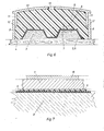
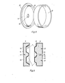
Figur 3 den extruderfernen Teil des Werkzeugs, teilweise im Schnitt X-X der Fig. 1, bestehend aus einer erfindungsgemäßen, der Oberflächengestalt der Kunststoffschale Fig. 1 entsprechenden Edelstahl-Formschale mit einer Epoxydharz-Quarzsand-Hinterfüllung und in einem Stahlgehäuse mit Stahldeckel gebettet,Figur 4 den extrudernahen Teil des Werkzeugs, teilweise im Schnitt X-X der Fig. 2, bestehend aus einer erfindungsgemäßen, der Oberflächengestalt der Kunststoffschale Fig. 2 entsprechenden Edelstahl-Formschale mit einer Epoxydharz-Quarzsand-Hinterfüllung, gebettet in einem Stahlgehäuse,Figur 5 das aus den Werkzeugteilen Fig. 3 und Fig. 4 zusammengesetzte Werkzeug am Extruder, im Schnitt X-X derFiguren 3 und 4 (der Spritzeinheit des Extruders teilweise im Schnitt),Figur 6 den extruderfernen Werkzeugteil Fig. 3, hergestellt an einem der Oberfläche der Schale Fig. 1 entsprechend gestalteten Primärformkern aus Gips, umgeben von einem Stahlgehäuse mit Deckel, das die aus Epoxydharz und Quarzsand bestehende Hinterfüllung aufnimmt,Figur 7 eine stark vergrößerte Darstellung des Ausschnittes "A" der Fig. 6, jedoch ohne das Symbol der Hinterfüllung,Figur 8 das Stahlgehäuse mit Deckel, beide in perspektivischer Sicht undFigur 9 die beiden Werkzeuge mit Hinterfüllung aus Metallguß und mit entsprechend vereinfachtem Gehäusedeckel.
- FIG. 1 shows the front view of a plastic shell (prototype) to be created with such a tool, in a perspective view,
- 2 shows the plastic shell FIG. 1 in a rear view,
- 3 shows the part of the tool remote from the extruder, partly in section XX of FIG. 1, consisting of a stainless steel molded shell according to the invention, corresponding to the surface shape of the plastic shell FIG. 1, with an epoxy resin quartz sand backfill and embedded in a steel housing with a steel cover,
- 4 shows the part of the tool near the extruder, partly in section XX of FIG. 2, consisting of a stainless steel molded shell according to the invention, corresponding to the surface shape of the plastic shell FIG. 2, with an epoxy resin quartz sand backfill, embedded in a steel housing,
- 5 shows the tool on the extruder assembled from the tool parts of FIGS. 3 and 4, in section XX of FIGS. 3 and 4 (the injection unit of the extruder partly in section),
- 6 shows the extruded tool part FIG. 3, produced on a primary mold core made of gypsum corresponding to the surface of the shell FIG. 1, surrounded by a steel housing with a cover which accommodates the backfilling consisting of epoxy resin and quartz sand,
- FIG. 7 shows a greatly enlarged illustration of the detail “A” from FIG. 6, but without the symbol of the backfill,
- Figure 8 shows the steel housing with cover, both in perspective and
- Figure 9 shows the two tools with backfill made of cast metal and with a correspondingly simplified housing cover.
Die auf den Figuren angebrachten Bezugsziffern' zeigen an :
- 1, 2 Prototypen des zu erstellenden Werkstücks
- 3 Primärformkern
- 4 Unterlage für den
Primärformkern 3 - 5 wasserfeste Deckschicht auf dem
Primärformkern 3 - 6 wasserlösliche Trennschicht
- 7 Edelstahlschicht
- 8 Gehäuse um die
Edelstahlschicht 7 - 9 Hinterfüllung an der
Edelstahlschicht 7 - 10 Deckel des
Gehäuses 8 - 11 Deckelrand
- 12 kegelmantelförmige Schräge des
Deckelrandes 11 - 13 Öffnung in der Deckelmitte
- 14 extruderfernen Werkzeugteil
- 15 extrudernahen Werkzeugteil
- 16 metallische Hinterfüllung
- 17 Schrauben zur Befestigung des
randlosen Deckels 10 - 18 Kupferschicht auf der.Edelstahlschicht 7
- A Ausschnitt aus Fig.6 (Fig.7)
- B Angußbohrung im
Werkzeugteil 15 - E Spritzteil des Extruders
- 1, 2 prototypes of the workpiece to be created
- 3 primary mold core
- 4 base for the
primary mold core 3 - 5 waterproof cover layer on the
primary mold core 3 - 6 water-soluble separating layer
- 7 stainless steel layer
- 8 housing around the
stainless steel layer 7 - 9 Backfilling on the
stainless steel layer 7 - 10 cover of
housing 8 - 11 lid edge
- 12 tapered bevel of the
lid edge 11 - 13 Opening in the middle of the lid
- 14 extruder-remote tool part
- 15 die part close to the extruder
- 16 metallic backfill
- 17 screws for fastening the
rimless cover 10 - 18 copper layer on the
stainless steel layer 7- A section from Fig. 6 (Fig. 7)
- B sprue hole in
tool part 15 - E extrusion molded part
Zunächst wird anhand von Prototypen 1,2 (Figuren 1 und 2) Primärformkerne 3 (Fig. 6) aus Gips erstellt. Der auf Fig. 6 gezeigte Primärformkern 3 entspricht der Oberflächengestalt des Prototyps 1. Der dem Prototyp 2 (Fig. 2) entsprechende Primärformkern (nicht gezeichnet) ist in analoger Weise aus Gips gegossen. Für die Primärformkerne können jedoch auch andere Materialien verwendet werden, sofern sie ohne sich zu verformen, Temperaturen um 100°C aufweisen, also z.B. Holz, Kunststoff u.ä. Der Primärformkern 3 muß wasserfest abisoliert, fettfrei und griffig sein.First,
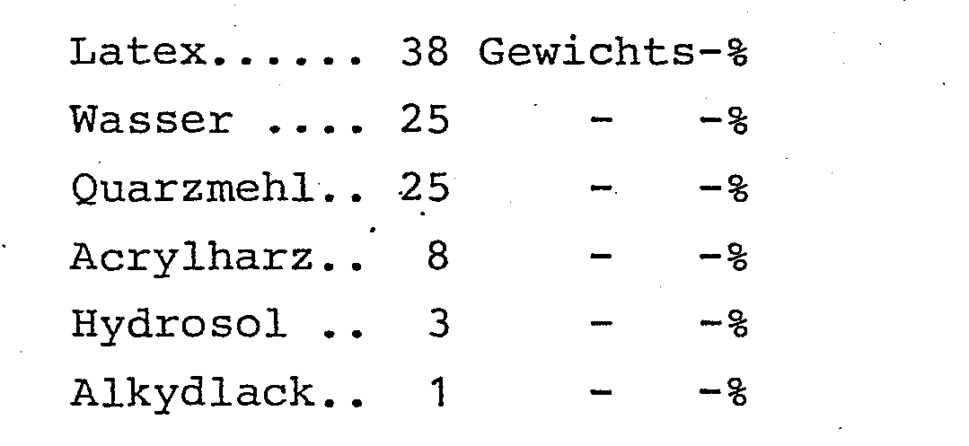
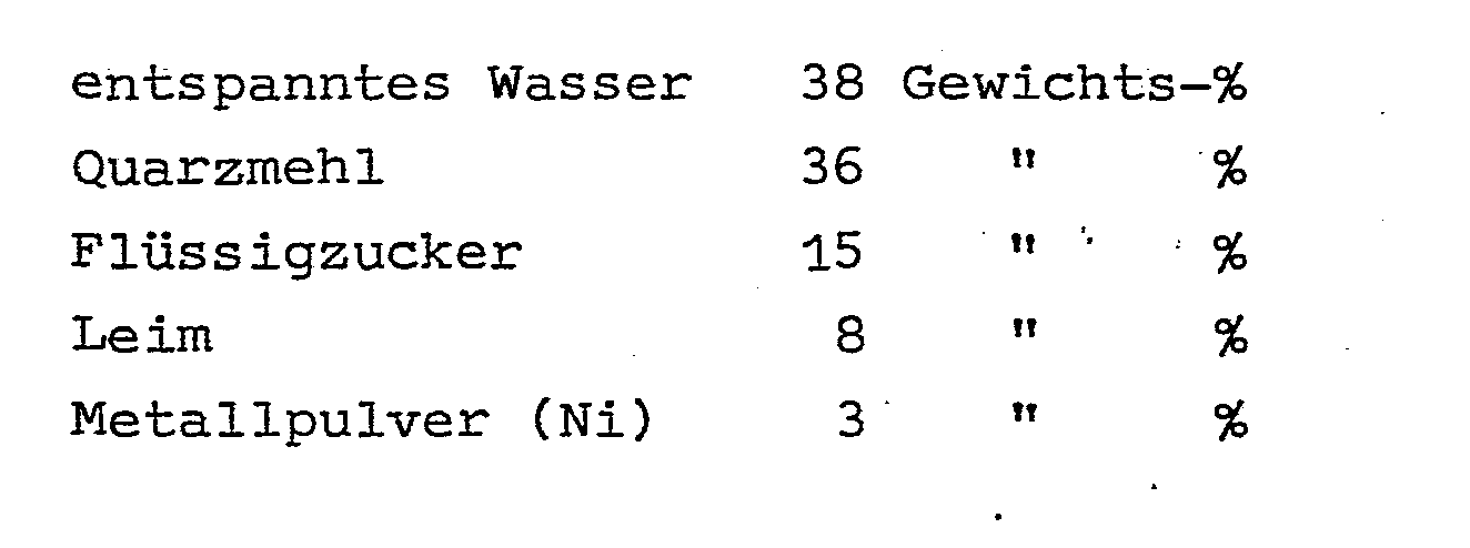
Jeder Primärformkern 3 wird auf je eine geometrisch ebene Unterlage 4 gestellt und die im Anspruch 2 angegebene wasserfeste Deckschicht 5 mit einer handelsüblichen Farbspritzpistole bis zu einer Schichtstärke 15 bis 30 my aufgetragen. Nach Austrocknen der Deckschicht 5 wird die im Anspruch 3 beschriebene wasserlösliche Trennschicht 6 aufgespritzt, und zwar bis etwa die gleiche Schichtstärke wie bei der Deckschicht 5. In den meisten Fällen reicht eine Gesamtschichtstärke 30 my für die beiden Schichten.Each
Zu der Natur der in den Ansprüchen 2 und 3 spezifizierten Lösungen ist zu sagen, daß die wasserfeste .Lösung 5 den Zweck hat, einen wasserfesten Film auf der Oberfläche des Primärformkerns 3 zu schaffen, der auch temperaturfest ist. Die wasserlösliche Lösung 6 bildet auf der wasserfesten Schicht 5 einen wasserlöslichen Filn, der derart zusammengesetzt ist, daß er selbst unter dem Aufprall und der Wärmewirkung des Metallspritzstrahls keine Verbindung mit der wasserfesten Schicht 5 eingeht, also von diesem chemisch und mechanisch betrennt bleibt.'Bei Primärformkernen 3 aus Gips, Holz, Kunststoff u.ä., an denen keine Temperaturen über rd. 100°C entstehen, kann die gleiche wasserfeste Schicht 5 für das Aufspritzen von vielen Edelstahlformen verwendet werden.Regarding the nature of the solutions specified in
Die in den Ansprüchen 2 und 3 angegebenen Rezepturen sind als optimale Beispiele zu werten. Innerhalb des in Anspruch 1 angegebenen Rahmen (ohne spezifische Mengenangabe) können mehrere brauchbare Rezepturen zusammengestellt werden..The recipes given in
Das Austrocknen der Schichten 5, 6 kann, wenn gewünscht, durch Wärme beschleunigt werden. Zum Zwecke einer besonders glatten Oberfläche des Primärformkerns kann man den Formkern vorsichtig abschleifen, muß dabei aber beachten, daß die Trennschicht 6 nicht durchgeschliffen wird.The drying of the
Dann trägt man mit der Metallspritzpistole geschmolzenes Edelstahl auf die beiden Primärformkerne 3 auf. Beim Aufspritzen ist darauf zu achten, daß keine Überhitzung der Edelstahlschicht 7 eintritt. Der Spritzabstand Spritzpistole-Primärformkern sollte mindestens etwa 30 bis 50 cm betragen, und das Aufspritzen erfolgt in mehreren Abschnitten, so daß nach jedem Spritz- .abschnitt eine kurze Pause eingelegt wird, damit das gespritzte Edelstahl sich jeweils abkühlen kann.Then molten stainless steel is applied to the two
Bei Temperaturen über etwa 130°C gibt die Trennschicht 6 die Edelstahlschicht 7 frei und läßt Druckluft bzw. Druckgas zwischen Primärformkern und Edelstahlschicht eindringen. Die Edelstahlschicht hebt von dem Primärformkern ab und ist danach unbrauchbar.At temperatures above about 130 ° C., the
Hier wirkt der hohe Gehalt an Kohlehydraten (Flüssigzucker, Anspruch 3) als Warnsignal : bereits bei 100°C verbrennt der Flüssigzucker unter Rauchentwicklung. Der Bediener der Spritzpistole weiß dann, daß er eine kurze Pause einlegen muß, damit die Edelstahlschicht abkühlen kann.Here the high content of carbohydrates (liquid sugar, claim 3) acts as a warning signal: even at 100 ° C, the liquid sugar burns with smoke. The operator of the spray gun then knows that he must take a short break so that the stainless steel layer can cool down.
Um eine Stärke der Edelstahlschicht 7"auf etwa 1 mm zu erreichen, bedarf es 15 bis 20 Einzelschichten. Für die Verwendung der Edelstahlschalen 7 als Formteile eines Werkzeugs zum Kunststoff-Spritzgießen braucht man jedoch derart dicke Schalen nicht, sondern kann sich mit wesentlich geringeren Stärken begnügen, etwa zwischen 0,1 und 0,5 mm, denn im Verbund des Werkzeugs hat die Edelstahlschale 7 keinerlei tragende Funktion, wie.weiter unten ausgeführt werden soll. Entscheidend für die Verwendung der Edelstahl-Formschale 7 als Spritzgußform ist in erster Linie die Härte des Materials. Im Gegensatz zu jedem anderen Verformungsprinzip spielt in dem vorliegenden Verfahren die Materialhärte keine Rolle : selbst die härtesten Chromstähle lassen sich ohne jede Schwierigkeit flammspritzen.In order to achieve a thickness of the
Falls das Auftragen des Edelstahls in einer sauerstoffreien Spritzkabine nach DE-GM 82 25 728 (später OS 32 33 925) stattfindet, werden die an den Primär-formkernen 3 ausgebildeten Edelstahl-Formschalen 7 sinterfrei sein und eine ähnliche Struktur aufweisen wie gegossene oder mittels Spanabhebung erstellte Werkstücke. Sie lassen sich dann auch dementsprechend polieren. Beim Aufspritzen von Edelstahl, insbesondere von Cr-V-Stahl oder Mo-A1-Stahl, in einer mit Stickstoff "gefüllten Spritzkabine erfolgt automatisch eine zusätzliche Nitrohärtung.If the application of the stainless steel takes place in an oxygen-free spray booth according to DE-GM 82 25 728 (later OS 32 33 925), the stainless steel molded
Nach Auskühlen der auf den Primär-Formkernen 3 aufliegenden Edelstahl-Formschalen 7 wird um jede Formschale 7 je ein nach oben und unten hin offenes Gehäuse 8 aufgestellt und bis zum Rand mit einer Mischung von Epoxydharz und Quarzsand, der Hinterfüllung 9, gefüllt. Auf das Gehäuse 8 wird ein Deckel 10 gelegt, der mit einem Deckelrand 11 in das Gehäuse 8 hineinragt. Der Deckelrand 11 weist eine kegelmantelförmige Schräge 12 auf. Der Deckel 10 besitzt in seiner Mitte eine Öffnung 13. Der Deckel 10 wird derart an das Gehäuse 8 herangedrückt, daß die Epoxydharz-Quarzsandmischung überall fest anliegt, auch an der Edelstahl-Formschale 7. Der Deckelrand 11 ist so dimensioniert, daß er nur mit Mühe in das Gehäuse 8 einzubringen ist, daß er also keine Sicherung braucht, um nicht fahrlässig herausgezogen werden oder gar herausfallen kann. Gehäuse 8 und Deckel 10 sind auf Figur 8 dargestellt.After the stainless
Die Hinterfüllung 9 kann auch aus einer Mischung Epoxydharz-Eisenpulver, Epoxydharz-Glaspulver (oder Glaskügelchen) bestehen; sie muß nur unbedingt unelastisch und unnachgiebig sein und sehr große Kräfte (Spritzkraft einerseits und Zuhaltekraft andererseits) aufnehmen ohne nachzugeben.The
Nach Einfüllen der Hinterfüllung 9 wird Wasser zwischen dem Primärformkern 3 und der Edelstahlschale 7 eingebracht. Die wasserlösliche Trennschicht 6 löst sich auf, und das Werkzeug 14,15 läßt sich vom Primärformkern trennen.After filling the
An dem in dem Werkzeugteil 15 angeordnete Angußbohrung B wird die Spritzeinheit E eines Extruders mit dem Gesamtwerkzeug 14,15 verbunden.-Auf den extruderfernen Werkzeugteil 14 wirkt die Zuhaltekraft, die der auf den extrudernahen Werkzeugteil einwirkenden Spritzkraft entspricht; das Gesamtwerkzeug 14,15 wird von diesen beiden Krften zusammengedrückt. Die Kräfte sind sehr groß; je nach Maschinengröße und Werkstückgröße kann sie zwischen 10 und 5000 Mp betragen. Da diese Kräfte auf die Deckel 10 einwirken, wird jede eventuelle Nachgiebigkeit der Hinterfüllungen 9 von den Deckeln aufgefangen, indem die Deckelränder 11 sich in die Hinterfüllungen 9 hineinschieben, soweit noch irgend eine Nachgiebigkeit dort vorhanden sein sollte.The injection unit E of an extruder is connected to the
Eine absolute Unnachgiebigkeit der Hinterfüllungen ist dadurch erreichbar, daß jede Hinterfüllung aus niederschmelzendem Metall erstellt wird, das in geschmolzenem Zustand in das Gehäuse 8 eingegossen wird. Dieses Vorgehen setzt voraus, daß die Edelstahlschalen 7 vorher auf eine Temperatur gebracht werden, die dem Schmelzpunkt des als Hinterfüllung vorgesehenen Metalls nahe ist, weil die Edelstahlschale sich sonst werfen könnte. Daher muß der Primärformkernv 3 aus entsprechend wärmefestem Material erstellt sein, z.B. aus Kupfer (Schmelzpunkt rd. 1080°C), während die Hinterfüllung dann aus Zink (Schmelzpunkt rd. 420°C) oder aus Bronze (Schmelzpunkt rd.700°C) bestehen kann.An absolute intransigence of the backfills can be achieved in that each backfill is made of low-melting metal, which is poured into the
Beim Aufheizen des Primärformkerns 3 und der Edelstahlschale 7 verbrennen Trennschicht 6 und Deckschicht 5, so daß die Abtrennung des Werkstückteils 14,15'beim Einfüllen der metallischen Hinterfüllung 16 bereits stattgefunden hat.When the
Da die metallische Hinterfüllung 16 gänzlich unnachgiebig ist, kann der Deckel 10 auf die Zuhaltekräfte einwirken, ohne Rand und Kragen auf der Hinterfüllung aufliegen und mit Schrauben 17 o.dgl. 'festgehalten werden, vgl. Fig. 9.Since the
Die metallische Hinterfüllung ist beim Metallspritzguß geboten, ferner bei der Herstellung von Automobilreifen, indem das Spritzgießen bei diesem Vorgang unter Temperaturen erfolgt, die ein Primärformkern aus Gips, Kunststoff u.ä. nicht verträgt. Die Erstellung von Werkzeugen für die Reifenfabrikation erfolgt segmentweise, und diese Segmentwerkzeuge werden dann zu einem ringförmigen Gesamtwerkzeug zusammengebaut.The metallic backfilling is required in metal injection molding, and also in the manufacture of automobile tires, in that the injection molding takes place in this process at temperatures which are a primary mold core made of plaster, plastic and the like. does not tolerate. Tire manufacturing tools are created segment by segment, and these segment tools are then assembled into a ring-shaped overall tool.
Wenn es darum geht, eine möglichst schnelle und gleichmäßige Wärmeableitung von der Edelstahlschale 7 zu erhalten, ist es zweckmäßig, nach Aufspritzen und Abkühlen der Edelstahlschale 7 eine Kupferschicht 18 aufzuspritzen.If it is a matter of obtaining heat dissipation from the
Claims (8)
dadurch gekennzeichnet, daß Edelstahl oder ein sonstiges geeignetes Metall oder Keramik im geschmolzenem Zustand auf einen Primärformkern (3) aufgespritzt wird, der vorher zunächst mit einer aus einer wässerigen Lösung von Hydrosolen, Latices, Acrylharz, Quarzmehl und Alkydlack bestehenden wasserfesten Deckschicht (5) und nach deren Austrocknen mit einer aus einer wässerigen Lösung von Leim, Kohlehydraten, Quarzmehl und Metallpulver bestehenden wasserlöslichen Trennschicht (6) versehen ist, wonach die durch das Aufspritzen von Metall entstandene Metallformschale (7) mit einer Hinterfüllung (9,16) aus unnachgiebigem Material versehen und der aus Metallformschale (7) und Hinterfüllung (9,16) zusammengesetzte Formteil (14,15) durch Einbringen von Wasser in die wasserlösliche Trennschicht (6) vom Primärformkern (3) abgelöst wird.1. Process for creating molds for injection molding, in particular tools for injection molding plastic,
characterized in that stainless steel or another suitable metal or ceramic in the molten state is sprayed onto a primary mold core (3) which is first of all covered with a waterproof cover layer (5) and consisting of an aqueous solution of hydrosols, latices, acrylic resin, quartz powder and alkyd varnish and after drying, is provided with a water-soluble separating layer (6) consisting of an aqueous solution of glue, carbohydrates, quartz powder and metal powder, after which the metal shell (7) formed by spraying on metal is provided with a backfill (9, 16) made of non-compliant material and the molded part (14, 15) composed of metal mold shell (7) and backfill (9, 16) is detached from the primary mold core (3) by introducing water into the water-soluble separating layer (6).
Priority Applications (1)
| Application Number | Priority Date | Filing Date | Title |
|---|---|---|---|
| AT84100577T ATE34332T1 (en) | 1983-02-07 | 1984-01-20 | PROCESS FOR MAKING MOLDS FOR INJECTION MOLDING, IN PARTICULAR TOOLS FOR PLASTIC INJECTION MOLDING. |
Applications Claiming Priority (2)
| Application Number | Priority Date | Filing Date | Title |
|---|---|---|---|
| DE3304073 | 1983-02-07 | ||
| DE19833304073 DE3304073A1 (en) | 1983-02-07 | 1983-02-07 | METHOD FOR CREATING MOLDS FOR INJECTION MOLDING, ESPECIALLY TOOLS FOR INJECTION MOLDING PLASTIC |
Publications (3)
| Publication Number | Publication Date |
|---|---|
| EP0117985A2 true EP0117985A2 (en) | 1984-09-12 |
| EP0117985A3 EP0117985A3 (en) | 1986-01-15 |
| EP0117985B1 EP0117985B1 (en) | 1988-05-18 |
Family
ID=6190193
Family Applications (1)
| Application Number | Title | Priority Date | Filing Date |
|---|---|---|---|
| EP84100577A Expired EP0117985B1 (en) | 1983-02-07 | 1984-01-20 | Method of producing moulds for injection moulding, particularly tools for the injection moulding of plastic materials |
Country Status (13)
| Country | Link |
|---|---|
| US (1) | US4777002A (en) |
| EP (1) | EP0117985B1 (en) |
| JP (1) | JPS59193748A (en) |
| KR (1) | KR840007538A (en) |
| AT (1) | ATE34332T1 (en) |
| AU (1) | AU561078B2 (en) |
| CA (1) | CA1229712A (en) |
| DE (2) | DE3304073A1 (en) |
| ES (1) | ES529527A0 (en) |
| HK (1) | HK38189A (en) |
| IN (1) | IN159222B (en) |
| SG (1) | SG84588G (en) |
| ZA (1) | ZA84534B (en) |
Cited By (2)
| Publication number | Priority date | Publication date | Assignee | Title |
|---|---|---|---|---|
| GB2319205A (en) * | 1996-11-13 | 1998-05-20 | Alan Roger Harper | Process for the manufacture of a mould tool |
| DE102016211051A1 (en) * | 2016-06-21 | 2017-12-21 | Bayerische Motoren Werke Aktiengesellschaft | Shaping tool and method of making a forming tool |
Families Citing this family (20)
| Publication number | Priority date | Publication date | Assignee | Title |
|---|---|---|---|---|
| DE3712192A1 (en) * | 1987-04-10 | 1988-10-27 | Alban Puetz | METALIZED TEXTILE TRACK AND METHOD FOR THE PRODUCTION THEREOF |
| US5151232A (en) * | 1987-09-26 | 1992-09-29 | Games Workshop Limited | Injection moulding process |
| JPH02280999A (en) * | 1989-04-18 | 1990-11-16 | Nkk Corp | Method for forming powder of metal, ceramic or the like |
| DE3917423C1 (en) * | 1989-05-29 | 1990-05-31 | Buerkert Gmbh & Co Werk Ingelfingen, 7118 Ingelfingen, De | |
| JPH0324202A (en) * | 1989-06-22 | 1991-02-01 | Nkk Corp | Method for forming powder body of metal, ceramic and the like |
| US5630305A (en) * | 1991-08-26 | 1997-05-20 | Hlasnicek; Richard S. | Surface covering unit methods of use and manufacture |
| JPH05171398A (en) * | 1991-12-25 | 1993-07-09 | Chugoku Kako Kk | Production of composite product having sprayed metal layer and mold release agent used therefor |
| US5296183A (en) * | 1992-08-21 | 1994-03-22 | Dow-United Technologies Composite Products, Inc. | Method for comolding property enhancing coatings to composite articles |
| US5449483A (en) * | 1994-02-04 | 1995-09-12 | The Goodyear Tire & Rubber Company | Method and apparatus for making a tire mold |
| DE19539449A1 (en) * | 1995-10-24 | 1997-04-30 | Biotronik Mess & Therapieg | Process for the production of intraluminal stents from bioresorbable polymer material |
| EP0861145B1 (en) * | 1995-11-13 | 2003-06-04 | GMIC, Corp. | Fabrication of tooling by thermal spraying |
| US5749409A (en) * | 1995-12-18 | 1998-05-12 | General Motors Corporation | Method of forming refractory coated foundry core |
| EP0925894A1 (en) * | 1997-12-23 | 1999-06-30 | P.C.R. S.R.L. | A process and an injection mold assembly for making moulds and prototypes |
| US20020110649A1 (en) * | 2000-05-09 | 2002-08-15 | Skszek Timothy W. | Fabrication of alloy variant structures using direct metal deposition |
| US6472029B1 (en) * | 1998-06-30 | 2002-10-29 | The P.O.M. Group | Fabrication of laminate structures using direct metal deposition |
| US6171091B1 (en) | 1999-05-12 | 2001-01-09 | Callaway Golf Company | Replaceable mold cavities and mold cavity inserts |
| US6838046B2 (en) | 2001-05-14 | 2005-01-04 | Honeywell International Inc. | Sintering process and tools for use in metal injection molding of large parts |
| US6770114B2 (en) | 2001-12-19 | 2004-08-03 | Honeywell International Inc. | Densified sintered powder and method |
| DE102012218928A1 (en) * | 2012-10-17 | 2014-04-17 | Krones Ag | Production method for blow molding |
| US9914848B1 (en) | 2016-10-31 | 2018-03-13 | Ppg Architectural Finishes, Inc. | Refinish coating composition |
Citations (6)
| Publication number | Priority date | Publication date | Assignee | Title |
|---|---|---|---|---|
| DE537839C (en) * | 1928-06-06 | 1931-11-17 | Budd Edward G Mfg Co | Die, especially for pressing sheet metal parts |
| US2293571A (en) * | 1939-05-22 | 1942-08-18 | Otto Stossel | Production of spray metal negatives of models |
| FR1341065A (en) * | 1958-07-11 | 1963-10-25 | Metal coated parts and their manufacturing process | |
| DE1577073B2 (en) * | 1965-12-15 | 1973-07-19 | The Budd Co., Philadelphia, Pa. (V.St. A.) | METHOD OF MANUFACTURING A DIE ELEMENT USED FOR PRESSING SHEET METAL COMPONENTS |
| DE2513777A1 (en) * | 1975-03-27 | 1976-10-07 | Agfa Gevaert Ag | METHOD OF MANUFACTURING A PRESSING STAMP |
| US4116753A (en) * | 1976-06-14 | 1978-09-26 | Olympus Optical Co., Ltd. | Method for the manufacture of optical mold for reproducing curved surfaces having the same shape as an optical prototype |
Family Cites Families (5)
| Publication number | Priority date | Publication date | Assignee | Title |
|---|---|---|---|---|
| US3136011A (en) * | 1960-02-13 | 1964-06-09 | Renault | Methods of preparing casting moulds |
| US3215763A (en) * | 1960-10-31 | 1965-11-02 | Albert J Buerger | Method for making a mold |
| US3405212A (en) * | 1966-02-17 | 1968-10-08 | Weyerhaeuser Co | Method of making metal clad tools |
| BE758096A (en) * | 1969-11-03 | 1971-04-01 | Goodyear Tire & Rubber | SOFT MOLD AND ITS MANUFACTURING PROCESS |
| US4225109A (en) * | 1978-07-06 | 1980-09-30 | Osaka City & Taiyo Manufacturing Works Co., Ltd. | Insulated metal mold |
-
1983
- 1983-02-07 DE DE19833304073 patent/DE3304073A1/en not_active Withdrawn
-
1984
- 1984-01-20 EP EP84100577A patent/EP0117985B1/en not_active Expired
- 1984-01-20 AT AT84100577T patent/ATE34332T1/en not_active IP Right Cessation
- 1984-01-20 DE DE8484100577T patent/DE3471276D1/en not_active Expired
- 1984-01-24 ZA ZA84534A patent/ZA84534B/en unknown
- 1984-01-31 CA CA000446436A patent/CA1229712A/en not_active Expired
- 1984-02-01 AU AU23959/84A patent/AU561078B2/en not_active Ceased
- 1984-02-06 KR KR1019840000552A patent/KR840007538A/en not_active Application Discontinuation
- 1984-02-07 JP JP59019562A patent/JPS59193748A/en active Pending
- 1984-02-07 IN IN81/MAS/84A patent/IN159222B/en unknown
- 1984-02-07 ES ES529527A patent/ES529527A0/en active Granted
-
1986
- 1986-09-30 US US06/913,738 patent/US4777002A/en not_active Expired - Lifetime
-
1988
- 1988-11-30 SG SG845/88A patent/SG84588G/en unknown
-
1989
- 1989-05-11 HK HK381/89A patent/HK38189A/en unknown
Patent Citations (6)
| Publication number | Priority date | Publication date | Assignee | Title |
|---|---|---|---|---|
| DE537839C (en) * | 1928-06-06 | 1931-11-17 | Budd Edward G Mfg Co | Die, especially for pressing sheet metal parts |
| US2293571A (en) * | 1939-05-22 | 1942-08-18 | Otto Stossel | Production of spray metal negatives of models |
| FR1341065A (en) * | 1958-07-11 | 1963-10-25 | Metal coated parts and their manufacturing process | |
| DE1577073B2 (en) * | 1965-12-15 | 1973-07-19 | The Budd Co., Philadelphia, Pa. (V.St. A.) | METHOD OF MANUFACTURING A DIE ELEMENT USED FOR PRESSING SHEET METAL COMPONENTS |
| DE2513777A1 (en) * | 1975-03-27 | 1976-10-07 | Agfa Gevaert Ag | METHOD OF MANUFACTURING A PRESSING STAMP |
| US4116753A (en) * | 1976-06-14 | 1978-09-26 | Olympus Optical Co., Ltd. | Method for the manufacture of optical mold for reproducing curved surfaces having the same shape as an optical prototype |
Cited By (3)
| Publication number | Priority date | Publication date | Assignee | Title |
|---|---|---|---|---|
| GB2319205A (en) * | 1996-11-13 | 1998-05-20 | Alan Roger Harper | Process for the manufacture of a mould tool |
| GB2319205B (en) * | 1996-11-13 | 2001-06-13 | Alan Roger Harper | Tooling |
| DE102016211051A1 (en) * | 2016-06-21 | 2017-12-21 | Bayerische Motoren Werke Aktiengesellschaft | Shaping tool and method of making a forming tool |
Also Published As
| Publication number | Publication date |
|---|---|
| IN159222B (en) | 1987-04-11 |
| KR840007538A (en) | 1984-12-08 |
| HK38189A (en) | 1989-05-19 |
| AU561078B2 (en) | 1987-04-30 |
| JPS59193748A (en) | 1984-11-02 |
| AU2395984A (en) | 1984-08-16 |
| ATE34332T1 (en) | 1988-06-15 |
| ES8501289A1 (en) | 1984-11-16 |
| ES529527A0 (en) | 1984-11-16 |
| US4777002A (en) | 1988-10-11 |
| DE3471276D1 (en) | 1988-06-23 |
| EP0117985A3 (en) | 1986-01-15 |
| ZA84534B (en) | 1984-09-26 |
| SG84588G (en) | 1989-09-01 |
| CA1229712A (en) | 1987-12-01 |
| EP0117985B1 (en) | 1988-05-18 |
| DE3304073A1 (en) | 1984-08-09 |
Similar Documents
| Publication | Publication Date | Title |
|---|---|---|
| EP0117985B1 (en) | Method of producing moulds for injection moulding, particularly tools for the injection moulding of plastic materials | |
| DE2831292C2 (en) | Method of making a lost core for casting a turbine blade | |
| DE4139214A1 (en) | TRIM BAR AND METHOD FOR THEIR PRODUCTION | |
| DE4325561A1 (en) | Non-sand core for casting or moulding - used in prodn. of metal, plastic or ceramic article with cavity and undercut or recessed section | |
| DE3515927A1 (en) | INJECTION MOLDING DEVICE AND METHOD FOR PRODUCING AN OBJECT IN SUCH A DEVICE | |
| DE102014011135B4 (en) | Method and device for producing a decorative part | |
| DE3103619C2 (en) | ||
| DE2352492A1 (en) | METHOD OF MANUFACTURING VACUUM STABILIZED CASTING MOLDS | |
| DE60019430T2 (en) | METHOD FOR PRODUCING A FILTER ELEMENT | |
| EP3482905A1 (en) | Mould insert and method for moulding a structural member | |
| DE2346181C3 (en) | Process for the production of a last for the manufacture of shoes, as well as a casting mold therefor | |
| DE888602C (en) | Process for the production of permanent forms or model facilities | |
| DE102005039148A1 (en) | Method of machining individual workpiece has blank block clamped and machined to form recess which is filled with hardenable powder or granular material | |
| WO1994007580A1 (en) | Porcelain-like doll's head and process and device for making it | |
| DE1173618B (en) | Process for the production of hollow foundry cores from fast-hardening sands as well as a core molding device for carrying out the process | |
| DE19706432C2 (en) | Method of making jewelry | |
| DE4026824A1 (en) | Durable mould tools for thermoplastics - consists of thin metal layer covering heater element and solid rear filling made by hot setting fluoro:polymer mixed with iron particles | |
| DE102007001303B4 (en) | Process for producing a filling body for a core box | |
| DE2044965A1 (en) | Permanent metal mould - for moulding plastic articles with electropla and cast aluminium mould parts | |
| DE2130129A1 (en) | Pre-fabricated radius edges for foundry moulds etc - - made from plastic | |
| DE102005005097B3 (en) | Mould manufacturing device for e.g. handle, has half emulation of small ceramic object formed on even surface of form block, which forms cut surface for half mould, and framework surrounding emulation and arranged on additional surface | |
| DE3505392A1 (en) | Process for producing pipe shells or pipes having an inner coating of corrosion-resistant material | |
| DE2445641A1 (en) | Negative mould prodn. for investment casting - for fabrication of lost wax or plastics patterns | |
| DE19752756C1 (en) | Method of production of jewelry | |
| DE3435091A1 (en) | Process for producing foamed mouldings with an improved surface and mouldings from foamed plastic |
Legal Events
| Date | Code | Title | Description |
|---|---|---|---|
| PUAI | Public reference made under article 153(3) epc to a published international application that has entered the european phase |
Free format text: ORIGINAL CODE: 0009012 |
|
| AK | Designated contracting states |
Designated state(s): AT BE CH DE FR GB IT LI LU NL SE |
|
| 17P | Request for examination filed |
Effective date: 19841127 |
|
| PUAL | Search report despatched |
Free format text: ORIGINAL CODE: 0009013 |
|
| AK | Designated contracting states |
Designated state(s): AT BE CH DE FR GB IT LI LU NL SE |
|
| 17Q | First examination report despatched |
Effective date: 19860826 |
|
| D17Q | First examination report despatched (deleted) | ||
| GRAA | (expected) grant |
Free format text: ORIGINAL CODE: 0009210 |
|
| AK | Designated contracting states |
Kind code of ref document: B1 Designated state(s): AT BE CH DE FR GB IT LI LU NL SE |
|
| REF | Corresponds to: |
Ref document number: 34332 Country of ref document: AT Date of ref document: 19880615 Kind code of ref document: T |
|
| REF | Corresponds to: |
Ref document number: 3471276 Country of ref document: DE Date of ref document: 19880623 |
|
| GBT | Gb: translation of ep patent filed (gb section 77(6)(a)/1977) | ||
| ITF | It: translation for a ep patent filed |
Owner name: JACOBACCI & PERANI S.P.A. |
|
| ET | Fr: translation filed | ||
| PG25 | Lapsed in a contracting state [announced via postgrant information from national office to epo] |
Ref country code: LU Free format text: LAPSE BECAUSE OF NON-PAYMENT OF DUE FEES Effective date: 19890131 |
|
| PGFP | Annual fee paid to national office [announced via postgrant information from national office to epo] |
Ref country code: NL Payment date: 19890131 Year of fee payment: 9 |
|
| PLBE | No opposition filed within time limit |
Free format text: ORIGINAL CODE: 0009261 |
|
| STAA | Information on the status of an ep patent application or granted ep patent |
Free format text: STATUS: NO OPPOSITION FILED WITHIN TIME LIMIT |
|
| 26N | No opposition filed | ||
| REG | Reference to a national code |
Ref country code: CH Ref legal event code: PL |
|
| PGFP | Annual fee paid to national office [announced via postgrant information from national office to epo] |
Ref country code: FR Payment date: 19891229 Year of fee payment: 7 |
|
| PGFP | Annual fee paid to national office [announced via postgrant information from national office to epo] |
Ref country code: GB Payment date: 19900131 Year of fee payment: 7 |
|
| PGFP | Annual fee paid to national office [announced via postgrant information from national office to epo] |
Ref country code: LU Payment date: 19900723 Year of fee payment: 7 |
|
| PGFP | Annual fee paid to national office [announced via postgrant information from national office to epo] |
Ref country code: CH Payment date: 19900727 Year of fee payment: 7 |
|
| PGFP | Annual fee paid to national office [announced via postgrant information from national office to epo] |
Ref country code: AT Payment date: 19900731 Year of fee payment: 7 Ref country code: BE Payment date: 19900731 Year of fee payment: 7 |
|
| REG | Reference to a national code |
Ref country code: CH Ref legal event code: AEN |
|
| PG25 | Lapsed in a contracting state [announced via postgrant information from national office to epo] |
Ref country code: AT Effective date: 19910120 Ref country code: GB Effective date: 19910120 |
|
| PG25 | Lapsed in a contracting state [announced via postgrant information from national office to epo] |
Ref country code: SE Effective date: 19910121 |
|
| ITTA | It: last paid annual fee | ||
| PG25 | Lapsed in a contracting state [announced via postgrant information from national office to epo] |
Ref country code: CH Effective date: 19910131 Ref country code: LI Effective date: 19910131 Ref country code: BE Effective date: 19910131 |
|
| PG25 | Lapsed in a contracting state [announced via postgrant information from national office to epo] |
Ref country code: NL Effective date: 19910801 |
|
| NLV4 | Nl: lapsed or anulled due to non-payment of the annual fee | ||
| GBPC | Gb: european patent ceased through non-payment of renewal fee | ||
| PG25 | Lapsed in a contracting state [announced via postgrant information from national office to epo] |
Ref country code: FR Effective date: 19910930 |
|
| REG | Reference to a national code |
Ref country code: CH Ref legal event code: PL |
|
| REG | Reference to a national code |
Ref country code: FR Ref legal event code: ST |
|
| EUG | Se: european patent has lapsed |
Ref document number: 84100577.0 Effective date: 19910910 |
|
| PGFP | Annual fee paid to national office [announced via postgrant information from national office to epo] |
Ref country code: DE Payment date: 19970626 Year of fee payment: 14 |
|
| PG25 | Lapsed in a contracting state [announced via postgrant information from national office to epo] |
Ref country code: DE Free format text: LAPSE BECAUSE OF NON-PAYMENT OF DUE FEES Effective date: 19981001 |
|
| PGFP | Annual fee paid to national office [announced via postgrant information from national office to epo] |
Ref country code: SE Payment date: 19900601 Year of fee payment: 7 |