EP0117162B1 - Procédé pour la détection d'une source de chaleur notamment d'un incendie de forêt dans une zone surveillée, et système pour la mise en oeuvre de ce procédé - Google Patents
Procédé pour la détection d'une source de chaleur notamment d'un incendie de forêt dans une zone surveillée, et système pour la mise en oeuvre de ce procédé Download PDFInfo
- Publication number
- EP0117162B1 EP0117162B1 EP84400030A EP84400030A EP0117162B1 EP 0117162 B1 EP0117162 B1 EP 0117162B1 EP 84400030 A EP84400030 A EP 84400030A EP 84400030 A EP84400030 A EP 84400030A EP 0117162 B1 EP0117162 B1 EP 0117162B1
- Authority
- EP
- European Patent Office
- Prior art keywords
- detector
- information
- heat
- infrared radiation
- central station
- Prior art date
- Legal status (The legal status is an assumption and is not a legal conclusion. Google has not performed a legal analysis and makes no representation as to the accuracy of the status listed.)
- Expired
Links
- 238000000034 method Methods 0.000 title claims description 25
- 238000001514 detection method Methods 0.000 title description 8
- 230000005855 radiation Effects 0.000 claims abstract description 46
- 238000012545 processing Methods 0.000 claims abstract description 17
- 230000005540 biological transmission Effects 0.000 claims abstract description 14
- 230000033001 locomotion Effects 0.000 claims abstract description 9
- 230000000737 periodic effect Effects 0.000 claims abstract 2
- 230000003287 optical effect Effects 0.000 claims description 15
- 230000010365 information processing Effects 0.000 claims description 4
- 238000006073 displacement reaction Methods 0.000 claims 2
- 238000011144 upstream manufacturing Methods 0.000 claims 2
- 238000012544 monitoring process Methods 0.000 description 10
- 230000003071 parasitic effect Effects 0.000 description 4
- 239000000779 smoke Substances 0.000 description 4
- 238000004458 analytical method Methods 0.000 description 3
- 238000007493 shaping process Methods 0.000 description 3
- 230000002123 temporal effect Effects 0.000 description 3
- 230000008901 benefit Effects 0.000 description 2
- 238000006243 chemical reaction Methods 0.000 description 2
- 238000010586 diagram Methods 0.000 description 2
- 239000003517 fume Substances 0.000 description 2
- 238000005259 measurement Methods 0.000 description 2
- 230000008569 process Effects 0.000 description 2
- 238000012795 verification Methods 0.000 description 2
- YBNMDCCMCLUHBL-UHFFFAOYSA-N (2,5-dioxopyrrolidin-1-yl) 4-pyren-1-ylbutanoate Chemical compound C=1C=C(C2=C34)C=CC3=CC=CC4=CC=C2C=1CCCC(=O)ON1C(=O)CCC1=O YBNMDCCMCLUHBL-UHFFFAOYSA-N 0.000 description 1
- 238000006677 Appel reaction Methods 0.000 description 1
- 238000010521 absorption reaction Methods 0.000 description 1
- 238000000862 absorption spectrum Methods 0.000 description 1
- 230000009471 action Effects 0.000 description 1
- 230000003321 amplification Effects 0.000 description 1
- 230000008859 change Effects 0.000 description 1
- 238000004891 communication Methods 0.000 description 1
- 230000006835 compression Effects 0.000 description 1
- 238000007906 compression Methods 0.000 description 1
- 238000011161 development Methods 0.000 description 1
- 230000002349 favourable effect Effects 0.000 description 1
- 230000006870 function Effects 0.000 description 1
- 230000000977 initiatory effect Effects 0.000 description 1
- 230000004807 localization Effects 0.000 description 1
- 238000004519 manufacturing process Methods 0.000 description 1
- 238000003199 nucleic acid amplification method Methods 0.000 description 1
- 230000035515 penetration Effects 0.000 description 1
- 230000011664 signaling Effects 0.000 description 1
- 230000003595 spectral effect Effects 0.000 description 1
- 238000010408 sweeping Methods 0.000 description 1
- 230000009897 systematic effect Effects 0.000 description 1
- 230000001052 transient effect Effects 0.000 description 1
- 230000001960 triggered effect Effects 0.000 description 1
Images

Classifications
-
- G—PHYSICS
- G08—SIGNALLING
- G08B—SIGNALLING OR CALLING SYSTEMS; ORDER TELEGRAPHS; ALARM SYSTEMS
- G08B17/00—Fire alarms; Alarms responsive to explosion
- G08B17/005—Fire alarms; Alarms responsive to explosion for forest fires, e.g. detecting fires spread over a large or outdoors area
-
- G—PHYSICS
- G08—SIGNALLING
- G08B—SIGNALLING OR CALLING SYSTEMS; ORDER TELEGRAPHS; ALARM SYSTEMS
- G08B17/00—Fire alarms; Alarms responsive to explosion
- G08B17/12—Actuation by presence of radiation or particles, e.g. of infrared radiation or of ions
Definitions
- the subject of the present invention is a method for detecting a heat source which may appear in a predetermined area or space, if necessary of a large extent, in particular a fire in a forest, and a system for putting it implementing this process.
- French patent application No. 2 224 818 discloses a method and device for detecting fires by which the region to be monitored is angularly scanned at constant rate using at least one detector sensitive to the infrared radiation characteristic of a fire ; temporarily stores the successive intensities measured by the detector for the corresponding successive orientations; a spatial correlation is carried out between the intensity measured for each of the measurement orientations and an average intensity over all or part of the same lap, and / or a temporal correlation relating to the intensities measured during successive laps; and an alert is triggered in the event of a lack of spatial or temporal correlation, the information coming from different towers being able to be transmitted to a regional center to locate the suspect zone exactly.
- the known method and device do not allow discrimination between authorized smoke and a fire. Indeed, insofar as a spatial correlation is carried out between the intensity measured for each of the measurement orientations and an average intensity under all or part of the same turn, and / or a temporal correlation relating to the intensities measured during successive turns, the appearance of authorized smoke will necessarily be interpreted as a fire.
- the object of the present invention is to propose a method and a system for the detection of a heat source, in particular of a fire, which do not have the abovementioned drawbacks inherent in known methods and systems.
- the invention therefore relates to a method for the detection of heat sources, in particular forest fires, in a zone or space in particular of large extent, of the type consisting in monitoring said zone from at least one monitoring station. , transmit information relating to the detected heat sources to an information processing device and locate the heat source on the basis of information from the various monitoring stations, the area being monitored using a radiation detector infrared, characteristic of a heat source, at each monitoring station required to perform, periodically, and preferably permanently, angular sweeping movements of the area to be monitored; and characterized in that it consists in transmitting to a central station, via a transmission link, such as a telephone link, the information relating to all the heat sources detected by the infrared detectors and originating treatment devices; previously memorize at the central station the information relating to heat sources authorized to be disregarded; automatically compare the information from all infrared detectors to the central station with the information previously stored at the central station; determine at least one unauthorized newly appeared heat source from the comparison results and issue an alarm signal as soon as the
- the detector is moved in a step-by-step manner and the information that the detector has received during each corresponding stop phase is transmitted to the central station.
- the detector is caused to perform a scanning movement vertical during each stop phase, around a horizontal axis, the scanning advantageously being carried out at a high frequency.
- the information relating to the intensity of infrared radiation received during the stopping of each step or of several steps is transmitted to the aforementioned center in digital form, stores this information in the center and returns it to the detector device in which the information received from the center is compared with the information initially transmitted to it and indicates to the center with the following information, where appropriate by a bit of value "0 or" 1 s' there was equivalence between the information compared and invalidates the information stored in the center in the event of a difference.
- data is transmitted with each information relating to the intensity of infrared radiation such as a synchronization bit which is used in the center to synchronize the allocation to said information received relating to the radiation, information relating to the corresponding angular position of the detector.
- the system for implementing the method according to the present invention is characterized in that it comprises a central station equipped with a computer device, such as a computer device, connected to the information processing devices via a telephone line, said computer device comprising a memory in which the information relating to authorized heat sources of an area to be monitored and not to be taken into account is previously stored, which device is adapted to automatically compare each item of information the infrared detectors with the information previously stored in the memory and determining at least one source of newly appeared unauthorized heat from the results of the comparison.
- a computer device such as a computer device
- the detector is provided with means allowing vertical scanning during each angular position corresponding to a step of the detector.
- the vertical scanning means is formed by a mirror vibrating at a high frequency.
- the method and system according to the present invention are particularly suitable for detecting heat sources such as fires in large forests. It is therefore advantageous to describe the invention by taking as an application example a forest monitoring system as shown in FIG. 1. It should be noted that the invention is however in no way limited to such a application and can be used in any case where it is a question of detecting and locating in a predetermined area the appearance of an object or a phenomenon, mobile or immobile, which emits infrared radiation.
- the embodiment of the invention for the detection of forest fires, comprises a certain number of surveillance towers of which only one is represented. These towers are of sufficient height and are appropriately placed so that their top is located at a level above any fire sources to be detected in the monitored forest area.
- an equipment item comprising in particular an infrared radiation detector-detector assembly 2, rotatable around a substantially vertical axis in order to be able to perform a horizontal scanning movement, an optical encoder 3 associated with this assembly and intended for determine the angular positions of the latter, a device 4 for processing the signals produced by the detector and representative of the intensity of the infrared radiation received, as well as a modem 5 connected to a telephone line 6 and intended to adapt the electrical signals to the properties of the telephone line.
- an infrared radiation detector-detector assembly 2 rotatable around a substantially vertical axis in order to be able to perform a horizontal scanning movement
- an optical encoder 3 associated with this assembly and intended for determine the angular positions of the latter
- a device 4 for processing the signals produced by the detector and representative of the intensity of the infrared radiation received
- modem 5 connected to a telephone line 6 and intended to adapt the electrical signals to the properties of the telephone line.
- Telephone lines such as line 6 connect the various monitoring stations at the top of the towers 1 to a central station 7, advantageously a computer, via modems 8 and eight-channel multiplexers 9, each associated with eight modems.
- the reference numeral 10 designates a storage and archiving device associated with the computer 7.
- the telephone line link from the central station to the various surveillance stations could be replaced by any other means of communication.
- the type of link should be chosen according to the infrastructure already in place or which can be installed, easily and economically.
- This assembly 2 comprises an optical radiation collecting device, provided with an infrared filter 12, a spherical collecting mirror 13 and the detector proper 14 which is provided with a window 15 of rectangular shape according to FIG. 3.
- assembly surrounded in Figure 2 by a line in broken lines is rotatable about a vertical axis centered on the center of the slot 15 and on the detector located below and fixed.
- This assembly is driven in rotation by a stepping motor 16 according to the direction of rotation indicated at 17 so that the horizontal scanning movement can be carried out.
- the slot 15 which is part of the rotary assembly is shown in dotted lines in several angular positions above the fixed sensitive surface 18 of the detector 14.
- a vibrating mirror 20 is placed in the rotary assembly in the focal zone of the collecting optic 13 so as to move the image of the detector in the image focal plane of this optic or, in other words , so as to form on the fixed detector 14 the image of part of the vertical field.
- This mirror vibrates at a relatively high frequency for reasons which will be explained later.
- the angular optical encoder intended to define the angular position of the rotary assembly can be recognized during the scanning of the horizontal field.
- the objective of the system according to the present invention is to detect forest fires up to distances of up to 20 km. It is important that the information, that is to say the radiation emitted by a fire, is transmitted to the detector with the minimum of absorption.
- the absorption spectrum of the atmosphere of infrared radiation we note the existence of a certain number of spectral bands or windows which are particularly transparent to this radiation.
- the band of wavelengths ranging from 3 to 5.5 "" m is used as windows.
- the atmospheric transmission is good and the stray radiation such as for example the solar radiation is limited.
- This window proved to be advantageous for optimal monitoring 24 hours a day, so even in broad daylight.
- Detectors which are effective in this wavelength range are for example PbSe detectors, cooled to -45 ° C. It should however be noted that the choice of infrared radiation detector depends on the conditions and specific criteria of each application case.
- the optical encoder provided for defining the angular positions of the rotary optical system must therefore be able to differentiate 2 13 different directions per revolution.
- the fastest speed of analysis of the horizon will advantageously correspond to one revolution in 40 seconds.
- the analysis time of a sector is therefore approximately 5 ms corresponding to a frequency of 200 Hz.
- the detector is advantageous for the detector to have a bandwidth approximately 10 times greater, that is to say about 2 kHz.
- the vertical observation field and in particular the frequency of vertical scanning, the following should be taken into account: if the observation towers have an altitude of 40 m and if the upper limit of the vertical observation field is the horizontal direction, which avoids being in direct observation of the sun, except in the morning and in the evening, and taking as a lower limit a shadow zone of 200 m around the foot of the tower, we obtain a vertical field angle equal to 15 x 10- 2 rds. It should be noted that this gray area is relative, because any fire which would be born there will be immediately detected because of the fumes which would cross the observation area, at a distance very close to the detection system.
- this mirror advantageously vibrates at a sufficiently high frequency that the detector seems to see the entire vertical angular field at once. It is then advantageous to choose a vibration frequency of the order of 20 kHz, that is to say 100 times higher than the analysis frequency of a horizontal sector and 10 times higher than the upper limit of the detection system bandwidth (2 kHz).
- FIG. 4 represents another embodiment of the sensor-detector assembly for infrared radiation 2.
- This includes a device ; . sitive optical radiation collector, provided with the infrared filter 12, a device 13a forming an objective and the detector 14 provided with the window 15.
- the assembly surrounded in FIG. 4 and by a dashed line is rotatable about a vertical axis centered on the center of the slot 15 and on the detector 14 located below and fixed. This assembly is rotated in the same way as that of Figure 2 so that the drive means 16 has been omitted in Figure 4.
- a rotating mirror 20a in the direction of the needles d a watch is placed in the rotary assembly in the focal zone of the objective 13a so as to form on the fixed detector 14 the image of part of the vertical field.
- the mirror 20a has several reflecting surfaces 20,1-20, 8 arranged for example in an octagon and focuses the infrared radiation on the detector 14 via the converging lens 13b located above the detector 14 and the slot 15.
- the mirror rotates around of the axis passing through the center 0 of the octagon and perpendicular to the axis in phantom through the centers of the lens 13b, of the slot 15, and of the detector 14.
- the angular speed of rotation of the mirror 20a must be chosen so as to be high enough so that the detector seems to see the entire vertical angular field at once. This speed can be chosen in accordance with the vibration frequency of the mirror 20 defined above.
- the detector 2 emits an electrical signal directly proportional to the intensity of infrared radiation received. This signal is transmitted to the processing device 4 in which it is amplified at 22, shaped at 23, converted to 24 in digital form by an analog-digital converter and processed in a logic processing and transmission control circuit 25, before reaching modem 5, as shown in figure 8.
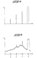
- FIG. 5 shows the electrical output signal from the detector 2 as a function of the angular position OEH of the rotary optical assembly of the detector, during the scanning of the horizontal field.
- This signal has peaks in a, b and c which are representative respectively of a light from 5 m to 20 km, from 5 m to 15 km and from 5 m to 5 km.
- the sudden rise in d of the output signal level is caused by the sun.
- sources of heat to be identified such as fire sources a, b and c, heat source d and others, will be made in the central station as described below.
- these peaks are characterized less by their amplitude relative to the parasitic background - amplitude which can be relatively small as in the case of the peak a - but rather by the shape of these ridges which is distinguished by very steep front and rear flanks, that is to say very short rise times.
- the pulses a ', b', and c 'and d' ( Figure 6), which correspond to the peaks a, b, c and d.
- the analog-digital converter 24 converts each pulse which contains the information of the intensity of an infrared radiation emitted by the heat source into an 8-bit digital signal.
- the module 25 first orders the signals so that they can be transmitted by the modem 5. Since the modem only accepts 8-bit signals in series, the module 25 combines the two pieces of information respectively of 13 parallel bits and 8 parallel bits into 8 bit serial information.
- Figures 8 and 9 illustrate the structure of the information bytes transmitted by the modem 5 to the central station 7 ( Figure 1).
- the module 25 should perform information compression. This consists first of all of not transmitting the 13 bits of angular position. In the 8-bit train sent to modem 5, only one bit is used for position tracking. This is a synchronization bit which is always in the low logic state "0 •, except when switching to the digital angular position 0000000000000 where the synchronization signal is at the high logic level" 1 This bit allows the reconstruction of information relating to the angular position in the central station.
- the latter comprises for this purpose a 13-bit counter which is reset to zero by the synchronization bit and which is incremented by one step with each new transmission of a byte.
- the precision of 8 bits is not necessary and one is satisfied with an accuracy of 3 bits.
- each byte shown is characterized by a synchronization bit D o , a D bit, error, 3 bits D 2 to D 4 of radiation intensity data relative to an angular position n ( Figure 8) or n + 2 (figure 9) and 3 bits D5 to D 7 of respective intensity data at the following angular position n + 1 (figure 8) or n + 3 (figure 9).
- Each byte thus formed is transmitted to the modem 5 which sends it to the modem 8 by the permanent telephone line 6.
- the byte is stored in the computer of the central station 7. It is then re-injected by the computer in the modem 8 which retransmits it to the modem 5 to arrive at the processing module 25.
- the latter compares the start byte and the return byte. If the two bytes are equivalent, the transmission was successful and the computer memorized correct data. If the two bytes are different, there has been a transmission error and the computer has stored false data.
- the transmission control logic processing module 25 acts on the control of the stepping motor 16 for driving the sensor formed by the rotary optical assembly of the detector 2.
- the motor places the sensor now in position n + 2.
- the sensor produces a new output signal which will be processed by the shaping circuit 23, after amplification at 22, and applied to the analog-digital converter 24.
- the module 25 then initiates the analog-digital conversion and stores the radiation intensity byte relative to the position n + 2. Then, the module 25 acts again on the rotation command of the motor 16, to place the sensor in the position n + 3. It triggers a new analog-digital conversion, then from the new data recorded, sends to the modem 5 the byte n + 2, n + 3 according to FIG.
- This byte contains in bit D, the information relating to the comparison of the previously transmitted byte containing the information relating to the angular positions n and n + 1 (FIG. 8). If the previous comparison operation has found a transmission error, the error bit of the new byte is in the high logic state "1" which causes the byte (n, n + 1) to be invalidated previously. recorded by the computer.
- the sources 7 were listed in the central station parasitic heat which should not be taken into account.
- the central station computer is provided with a memory in which information relating to sources has been recorded. To find out if a heat source identified by detector 2 is a fire, the computer performs, following the reception of each byte, after having associated with the information received the information relating to the angular position of the detector sensor , using its 13-bit counter and the synchronization bit D o contained in the byte received, a comparison with the content of its memory.
- the central station 7 or more exactly the computer permanently receives a flow of information from the various monitoring stations each equipped with an infrared radiation detector. If a heat source turns out to be a fire, it can be easily located from the start and action can be taken immediately to extinguish the start of the fire.
- the invention is in no way limited to the detection of a fire.
- the invention can be used to detect the appearance or penetration into a monitored area of any object or phenomenon giving rise to the emission of infrared radiation.
- the invention could thus be used to monitor, for example, a border.
Landscapes
- Business, Economics & Management (AREA)
- Emergency Management (AREA)
- Physics & Mathematics (AREA)
- General Physics & Mathematics (AREA)
- Life Sciences & Earth Sciences (AREA)
- Biodiversity & Conservation Biology (AREA)
- Fire Alarms (AREA)
- Fire-Detection Mechanisms (AREA)
- Photometry And Measurement Of Optical Pulse Characteristics (AREA)
- Geophysics And Detection Of Objects (AREA)
- Investigating Or Analyzing Materials Using Thermal Means (AREA)
- Alarm Systems (AREA)
- Emergency Alarm Devices (AREA)
Priority Applications (1)
| Application Number | Priority Date | Filing Date | Title |
|---|---|---|---|
| AT84400030T ATE41539T1 (de) | 1983-01-13 | 1984-01-06 | Verfahren fuer die detektion einer waermequelle insbesondere eines waldbrandes in einer ueberwachten zone und system zur durchfuehrung dieses verfahrens. |
Applications Claiming Priority (2)
| Application Number | Priority Date | Filing Date | Title |
|---|---|---|---|
| FR8300461 | 1983-01-13 | ||
| FR8300461A FR2541484B1 (fr) | 1983-01-13 | 1983-01-13 | Procede pour la detection d'une source de chaleur notamment d'un incendie de foret dans une zone surveillee, et systeme pour la mise en oeuvre de ce procede |
Publications (2)
| Publication Number | Publication Date |
|---|---|
| EP0117162A1 EP0117162A1 (fr) | 1984-08-29 |
| EP0117162B1 true EP0117162B1 (fr) | 1989-03-15 |
Family
ID=9284902
Family Applications (1)
| Application Number | Title | Priority Date | Filing Date |
|---|---|---|---|
| EP84400030A Expired EP0117162B1 (fr) | 1983-01-13 | 1984-01-06 | Procédé pour la détection d'une source de chaleur notamment d'un incendie de forêt dans une zone surveillée, et système pour la mise en oeuvre de ce procédé |
Country Status (11)
| Country | Link |
|---|---|
| US (1) | US4567367A (enExample) |
| EP (1) | EP0117162B1 (enExample) |
| AT (1) | ATE41539T1 (enExample) |
| AU (1) | AU576746B2 (enExample) |
| CA (1) | CA1229143A (enExample) |
| DE (1) | DE3477285D1 (enExample) |
| ES (1) | ES528840A0 (enExample) |
| FR (1) | FR2541484B1 (enExample) |
| GR (1) | GR79473B (enExample) |
| MA (1) | MA20004A1 (enExample) |
| PT (1) | PT77948B (enExample) |
Cited By (1)
| Publication number | Priority date | Publication date | Assignee | Title |
|---|---|---|---|---|
| EP4407579A3 (en) * | 2023-01-25 | 2024-10-16 | Honeywell Analytics Inc. | Methods, apparatuses, and systems for configuring a flame zone detecting apparatus |
Families Citing this family (26)
| Publication number | Priority date | Publication date | Assignee | Title |
|---|---|---|---|---|
| FR2572564B1 (fr) * | 1984-10-30 | 1986-12-19 | Macron Patrick | Appareil electronique de surveillance et de lutte contre l'intrusion |
| GB2171513B (en) * | 1985-02-19 | 1989-08-31 | Atomic Energy Authority Uk | Safety system for laser-utilising facilities |
| US4845629A (en) * | 1985-07-18 | 1989-07-04 | General De Investigacion Y Desarrollo S.A. | Airport surveillance systems |
| AU587447B2 (en) * | 1986-04-25 | 1989-08-17 | Hochiki Kabushiki Kaisha | Scanning fire-monitoring system |
| EP0298182A1 (fr) * | 1987-05-06 | 1989-01-11 | Societe Industrielle D'aviation Latecoere | Procédé et dispositif pour détecter les incendies |
| FR2598238A1 (fr) * | 1986-05-05 | 1987-11-06 | Latecoere Ste Indle Aviat | Procede et dispositif pour detecteur les incendies |
| IT1206251B (it) * | 1987-02-19 | 1989-04-14 | Teletron Srl | Sistema di controllo nel visibile e/o ad infrarossi particolarmente adatto per la prevenzione degli incendi |
| FR2614984A1 (fr) * | 1987-05-05 | 1988-11-10 | Argamakoff Aleksy | Detecteur automatique d'incendies de foret |
| FR2637977B1 (fr) * | 1988-10-13 | 1992-03-13 | Brown De Colstoun Francois | Procede et systeme pour la detection notamment de feu de forets |
| US4975584A (en) * | 1989-03-29 | 1990-12-04 | Mountain Ocean, Ltd. | Method and apparatus for collecting, processing and displaying ultraviolet radiation data |
| GR890100820A (el) * | 1989-12-13 | 1992-05-12 | Alexiou Apostolos D | Αυτοματο-αυτονομο συστημα τηλεπυρανιχνευσης και μεταδοσης χρησιμων πληροφοριων αντλουμενων απο το περιβαλλον. |
| FR2669455B1 (fr) * | 1990-11-21 | 1993-01-08 | Dassault Electronique | Installation de teledetection aerienne et/ou terrestre, notamment pour la detection des feux de forets. |
| FR2671196B1 (fr) * | 1990-12-27 | 1994-05-06 | Sopelem | Dispositif telemetrique pour la detection et la localisation d'objets ou de substances retrodiffusants. |
| US5160842A (en) * | 1991-06-24 | 1992-11-03 | Mid-Valley Helicopters, Inc. | Infrared fire-perimeter mapping |
| IL105772A (en) | 1992-06-01 | 1998-07-15 | Univ Florida | Methods and materials for pest control |
| ES2070710B1 (es) * | 1993-02-10 | 1997-05-01 | Nacional Bazan De Construccion | Sistema de vigilancia y deteccion de focos de calor en areas abiertas . |
| US5534697A (en) * | 1994-09-02 | 1996-07-09 | Rockwell International Corporation | Electro-optical sensor system for use in observing objects |
| US5502309A (en) * | 1994-09-06 | 1996-03-26 | Rockwell International Corporation | Staring sensor |
| US5627675A (en) * | 1995-05-13 | 1997-05-06 | Boeing North American Inc. | Optics assembly for observing a panoramic scene |
| US5841589A (en) * | 1995-09-26 | 1998-11-24 | Boeing North American, Inc. | Panoramic optics assembly having an initial flat reflective element |
| US5815090A (en) * | 1996-10-31 | 1998-09-29 | University Of Florida Research Foundation, Inc. | Remote monitoring system for detecting termites |
| GB2348531A (en) * | 1999-02-17 | 2000-10-04 | Bambour Olubukola Omoyiola | Forest fire detector unit |
| US6404210B1 (en) | 1999-03-02 | 2002-06-11 | University Of Florida Research Foundation, Inc. | Dimensionally stable sensor for monitoring termite activity |
| ITRM20040245A1 (it) * | 2004-05-14 | 2004-08-14 | Gen Contractor S R L | Metodo per il rilevamento volumetrico ottimizzato di eventi su un'area geografica, apparato utilizzante tale metodo e relativo sistema di rilevamento. |
| CN108520615B (zh) * | 2018-04-20 | 2020-08-25 | 吉林省林业科学研究院 | 一种基于图像的火灾识别系统和方法 |
| CN112991657A (zh) * | 2021-02-08 | 2021-06-18 | 四川省铭阳睿智科技有限公司 | 基于5g通信技术的森林火灾智能预警控制系统 |
Citations (1)
| Publication number | Priority date | Publication date | Assignee | Title |
|---|---|---|---|---|
| US3924130A (en) * | 1968-02-12 | 1975-12-02 | Us Navy | Body exposure indicator |
Family Cites Families (8)
| Publication number | Priority date | Publication date | Assignee | Title |
|---|---|---|---|---|
| US1959702A (en) * | 1930-04-22 | 1934-05-22 | George A Barker | Apparatus for detecting forest fires |
| US3987445A (en) * | 1963-02-11 | 1976-10-19 | Fales Iii David | Oblique scatter object detection and location system |
| GB1127443A (en) * | 1965-01-13 | 1968-09-18 | Thring S Advanced Developments | Improvements in or relating to fire detection and fighting apparatus |
| GB1089757A (en) * | 1965-08-14 | 1967-11-08 | Thrings Advanced Developments | Improvements in or relating to fire detection, alarm, and fighting apparatus |
| US3475608A (en) * | 1967-11-02 | 1969-10-28 | Us Army | Thermal,moving target,intrusion detector |
| FR2224818A1 (en) * | 1973-04-05 | 1974-10-31 | Onera (Off Nat Aerospatiale) | Forest fire detection appts - responsive to visible or infra red radiation in area surrounding observation post |
| US3941923A (en) * | 1974-04-01 | 1976-03-02 | Hughes Aircraft Company | Thermal imaging system with redundant object space scanning |
| AU6594080A (en) * | 1980-01-19 | 1981-07-30 | W. Vinten Ltd. | Intruder alarm systems |
-
1983
- 1983-01-13 FR FR8300461A patent/FR2541484B1/fr not_active Expired
-
1984
- 1984-01-06 AT AT84400030T patent/ATE41539T1/de not_active IP Right Cessation
- 1984-01-06 EP EP84400030A patent/EP0117162B1/fr not_active Expired
- 1984-01-06 DE DE8484400030T patent/DE3477285D1/de not_active Expired
- 1984-01-09 CA CA000444895A patent/CA1229143A/en not_active Expired
- 1984-01-09 AU AU23147/84A patent/AU576746B2/en not_active Ceased
- 1984-01-10 GR GR73459A patent/GR79473B/el unknown
- 1984-01-11 MA MA20225A patent/MA20004A1/fr unknown
- 1984-01-12 US US06/570,198 patent/US4567367A/en not_active Expired - Lifetime
- 1984-01-12 PT PT77948A patent/PT77948B/pt not_active IP Right Cessation
- 1984-01-12 ES ES528840A patent/ES528840A0/es active Granted
Patent Citations (1)
| Publication number | Priority date | Publication date | Assignee | Title |
|---|---|---|---|---|
| US3924130A (en) * | 1968-02-12 | 1975-12-02 | Us Navy | Body exposure indicator |
Cited By (1)
| Publication number | Priority date | Publication date | Assignee | Title |
|---|---|---|---|---|
| EP4407579A3 (en) * | 2023-01-25 | 2024-10-16 | Honeywell Analytics Inc. | Methods, apparatuses, and systems for configuring a flame zone detecting apparatus |
Also Published As
| Publication number | Publication date |
|---|---|
| DE3477285D1 (en) | 1989-04-20 |
| ES8407349A1 (es) | 1984-09-16 |
| PT77948A (fr) | 1984-02-01 |
| FR2541484B1 (fr) | 1986-06-13 |
| GR79473B (enExample) | 1984-10-30 |
| FR2541484A1 (fr) | 1984-08-24 |
| MA20004A1 (fr) | 1984-10-01 |
| EP0117162A1 (fr) | 1984-08-29 |
| CA1229143A (en) | 1987-11-10 |
| ES528840A0 (es) | 1984-09-16 |
| AU576746B2 (en) | 1988-09-08 |
| US4567367A (en) | 1986-01-28 |
| AU2314784A (en) | 1984-07-19 |
| ATE41539T1 (de) | 1989-04-15 |
| PT77948B (fr) | 1986-04-10 |
Similar Documents
| Publication | Publication Date | Title |
|---|---|---|
| EP0117162B1 (fr) | Procédé pour la détection d'une source de chaleur notamment d'un incendie de forêt dans une zone surveillée, et système pour la mise en oeuvre de ce procédé | |
| EP1364351B1 (fr) | Procede et dispositif de detection de feux base sur l'analyse d'images | |
| EP0364364B1 (fr) | Procédé et système pour la détection notamment de feu de forêts | |
| EP0494815B1 (fr) | Système de mesure du trafic de véhicules automobiles | |
| EP0146428A1 (fr) | Procédé et dispositif de guidage automatique de mobiles, en particulier de chariots automoteurs sans conducteur | |
| EP0379425A1 (fr) | Système de détermination de la position d'au moins une cible par triangulation | |
| FR2476325A1 (fr) | Systeme de reperage omnidirectionnel pour objets en mouvement | |
| WO1994008660A1 (fr) | Procede et dispositif de detection automatique rapide de feux de foret | |
| EP4308460A1 (fr) | Systeme de detection de la trajectoire d'objets mobiles | |
| EP0241374B1 (fr) | Système optronique d'écartométrie assurant la discrimination spatiale et spectrale des sources lumineuses infrarouges | |
| FR2661738A1 (fr) | Procede pour la detection et la poursuite d'un but, notamment d'un engin volant. | |
| EP0234164B1 (fr) | Station et système utilisant la rétrodiffusion de rayons laser pour détecter et localiser un objet ou une substance telle que la fumée d'incendie | |
| FR2608777A1 (fr) | Dispositif de detection d'intrusion et de reconnaissance de vehicules terrestres | |
| FR2684763A1 (fr) | Dispostif integre de detection et d'identification d'obstacles embarque notamment a bord d'un vehicule automobile. | |
| FR2675610A1 (fr) | Procede et installation d'evaluation d'un flux de circulation de vehicules routiers. | |
| CA2666030A1 (fr) | Procede et dispositif pour la detection d'un objet apte a retroreflechir la lumiere | |
| EP4080177B1 (fr) | Procédé et système de contrôle du niveau sonore maximal lié au déplacement d'un véhicule | |
| FR2751479A1 (fr) | Procede et systeme de protection des equipements de veille ou de poursuite optroniques au regard d'une illumination | |
| FR2612647A1 (fr) | Dispositif de modulation pour un dispositif detecteur de rayonnement captant un champ d'image | |
| EP1584079B1 (fr) | Procede de detection d'incident sur route | |
| EP0528077A1 (fr) | Système radar aéroporté muni d'une caméra pour poursuivre objets volants à basse altitude | |
| EP0558405A1 (fr) | Dispositif d'évaluation du balisage lumineux notamment sur les pistes et les voies d'accès des avions | |
| EP1105712A1 (fr) | Dispositif de mesure de la taille de particules en deplacement, notamment pour des mesures pluviometriques | |
| FR2643173A1 (fr) | Detecteur automatique d'intrusion ou incendie a grande distance | |
| FR2588967A1 (fr) | Procede et dispositif pour detecter des helicopteres |
Legal Events
| Date | Code | Title | Description |
|---|---|---|---|
| PUAI | Public reference made under article 153(3) epc to a published international application that has entered the european phase |
Free format text: ORIGINAL CODE: 0009012 |
|
| AK | Designated contracting states |
Designated state(s): AT BE CH DE GB IT LI LU NL SE |
|
| 17P | Request for examination filed |
Effective date: 19850222 |
|
| 17Q | First examination report despatched |
Effective date: 19860905 |
|
| GRAA | (expected) grant |
Free format text: ORIGINAL CODE: 0009210 |
|
| AK | Designated contracting states |
Kind code of ref document: B1 Designated state(s): AT BE CH DE GB IT LI LU NL SE |
|
| REF | Corresponds to: |
Ref document number: 41539 Country of ref document: AT Date of ref document: 19890415 Kind code of ref document: T |
|
| REF | Corresponds to: |
Ref document number: 3477285 Country of ref document: DE Date of ref document: 19890420 |
|
| ITF | It: translation for a ep patent filed | ||
| GBT | Gb: translation of ep patent filed (gb section 77(6)(a)/1977) | ||
| PLBE | No opposition filed within time limit |
Free format text: ORIGINAL CODE: 0009261 |
|
| STAA | Information on the status of an ep patent application or granted ep patent |
Free format text: STATUS: NO OPPOSITION FILED WITHIN TIME LIMIT |
|
| 26N | No opposition filed | ||
| ITTA | It: last paid annual fee | ||
| EPTA | Lu: last paid annual fee | ||
| EAL | Se: european patent in force in sweden |
Ref document number: 84400030.7 |
|
| PGFP | Annual fee paid to national office [announced via postgrant information from national office to epo] |
Ref country code: GB Payment date: 19961230 Year of fee payment: 14 |
|
| PGFP | Annual fee paid to national office [announced via postgrant information from national office to epo] |
Ref country code: LU Payment date: 19970101 Year of fee payment: 14 |
|
| PGFP | Annual fee paid to national office [announced via postgrant information from national office to epo] |
Ref country code: DE Payment date: 19970113 Year of fee payment: 14 |
|
| PGFP | Annual fee paid to national office [announced via postgrant information from national office to epo] |
Ref country code: AT Payment date: 19970114 Year of fee payment: 14 |
|
| PGFP | Annual fee paid to national office [announced via postgrant information from national office to epo] |
Ref country code: SE Payment date: 19970115 Year of fee payment: 14 |
|
| PGFP | Annual fee paid to national office [announced via postgrant information from national office to epo] |
Ref country code: CH Payment date: 19970120 Year of fee payment: 14 |
|
| PGFP | Annual fee paid to national office [announced via postgrant information from national office to epo] |
Ref country code: NL Payment date: 19970130 Year of fee payment: 14 |
|
| PGFP | Annual fee paid to national office [announced via postgrant information from national office to epo] |
Ref country code: BE Payment date: 19970318 Year of fee payment: 14 |
|
| PG25 | Lapsed in a contracting state [announced via postgrant information from national office to epo] |
Ref country code: LU Free format text: LAPSE BECAUSE OF NON-PAYMENT OF DUE FEES Effective date: 19980106 Ref country code: GB Free format text: LAPSE BECAUSE OF NON-PAYMENT OF DUE FEES Effective date: 19980106 Ref country code: AT Free format text: LAPSE BECAUSE OF NON-PAYMENT OF DUE FEES Effective date: 19980106 |
|
| PG25 | Lapsed in a contracting state [announced via postgrant information from national office to epo] |
Ref country code: SE Free format text: LAPSE BECAUSE OF NON-PAYMENT OF DUE FEES Effective date: 19980107 |
|
| PG25 | Lapsed in a contracting state [announced via postgrant information from national office to epo] |
Ref country code: LI Free format text: LAPSE BECAUSE OF NON-PAYMENT OF DUE FEES Effective date: 19980131 Ref country code: CH Free format text: LAPSE BECAUSE OF NON-PAYMENT OF DUE FEES Effective date: 19980131 Ref country code: BE Free format text: LAPSE BECAUSE OF NON-PAYMENT OF DUE FEES Effective date: 19980131 |
|
| BERE | Be: lapsed |
Owner name: MOSCOVI MICHEL Effective date: 19980131 Owner name: MOSCOVI JEAN-CLAUDE MARIAN Effective date: 19980131 Owner name: LE SAIGE DE LA VILLESBRUNNE ARNAUD GERARD Effective date: 19980131 Owner name: CHAMBARET YVES Effective date: 19980131 Owner name: CHAMBARET JEAN-PAUL Effective date: 19980131 Owner name: BROWN DE COLSTOUN FRANCOIS PATRICE DIDIER Effective date: 19980131 |
|
| PG25 | Lapsed in a contracting state [announced via postgrant information from national office to epo] |
Ref country code: NL Free format text: LAPSE BECAUSE OF NON-PAYMENT OF DUE FEES Effective date: 19980801 |
|
| GBPC | Gb: european patent ceased through non-payment of renewal fee |
Effective date: 19980106 |
|
| REG | Reference to a national code |
Ref country code: CH Ref legal event code: PL |
|
| NLV4 | Nl: lapsed or anulled due to non-payment of the annual fee |
Effective date: 19980801 |
|
| PG25 | Lapsed in a contracting state [announced via postgrant information from national office to epo] |
Ref country code: DE Free format text: LAPSE BECAUSE OF NON-PAYMENT OF DUE FEES Effective date: 19981001 |
|
| EUG | Se: european patent has lapsed |
Ref document number: 84400030.7 |