EP0117162B1 - Method for the detection of a heat source particularly of a forest fire in a controlled zone, and system for the application of this method - Google Patents
Method for the detection of a heat source particularly of a forest fire in a controlled zone, and system for the application of this method Download PDFInfo
- Publication number
- EP0117162B1 EP0117162B1 EP84400030A EP84400030A EP0117162B1 EP 0117162 B1 EP0117162 B1 EP 0117162B1 EP 84400030 A EP84400030 A EP 84400030A EP 84400030 A EP84400030 A EP 84400030A EP 0117162 B1 EP0117162 B1 EP 0117162B1
- Authority
- EP
- European Patent Office
- Prior art keywords
- detector
- information
- heat
- infrared radiation
- central station
- Prior art date
- Legal status (The legal status is an assumption and is not a legal conclusion. Google has not performed a legal analysis and makes no representation as to the accuracy of the status listed.)
- Expired
Links
- 238000000034 method Methods 0.000 title claims description 25
- 238000001514 detection method Methods 0.000 title description 8
- 230000005855 radiation Effects 0.000 claims abstract description 46
- 238000012545 processing Methods 0.000 claims abstract description 17
- 230000005540 biological transmission Effects 0.000 claims abstract description 14
- 230000033001 locomotion Effects 0.000 claims abstract description 9
- 230000000737 periodic effect Effects 0.000 claims abstract 2
- 230000003287 optical effect Effects 0.000 claims description 15
- 230000010365 information processing Effects 0.000 claims description 4
- 238000006073 displacement reaction Methods 0.000 claims 2
- 238000011144 upstream manufacturing Methods 0.000 claims 2
- 238000012544 monitoring process Methods 0.000 description 10
- 230000003071 parasitic effect Effects 0.000 description 4
- 239000000779 smoke Substances 0.000 description 4
- 238000004458 analytical method Methods 0.000 description 3
- 238000007493 shaping process Methods 0.000 description 3
- 230000002123 temporal effect Effects 0.000 description 3
- 230000008901 benefit Effects 0.000 description 2
- 238000006243 chemical reaction Methods 0.000 description 2
- 238000010586 diagram Methods 0.000 description 2
- 239000003517 fume Substances 0.000 description 2
- 238000005259 measurement Methods 0.000 description 2
- 230000008569 process Effects 0.000 description 2
- 238000012795 verification Methods 0.000 description 2
- YBNMDCCMCLUHBL-UHFFFAOYSA-N (2,5-dioxopyrrolidin-1-yl) 4-pyren-1-ylbutanoate Chemical compound C=1C=C(C2=C34)C=CC3=CC=CC4=CC=C2C=1CCCC(=O)ON1C(=O)CCC1=O YBNMDCCMCLUHBL-UHFFFAOYSA-N 0.000 description 1
- 238000006677 Appel reaction Methods 0.000 description 1
- 238000010521 absorption reaction Methods 0.000 description 1
- 238000000862 absorption spectrum Methods 0.000 description 1
- 230000009471 action Effects 0.000 description 1
- 230000003321 amplification Effects 0.000 description 1
- 230000008859 change Effects 0.000 description 1
- 238000004891 communication Methods 0.000 description 1
- 230000006835 compression Effects 0.000 description 1
- 238000007906 compression Methods 0.000 description 1
- 238000011161 development Methods 0.000 description 1
- 230000002349 favourable effect Effects 0.000 description 1
- 230000006870 function Effects 0.000 description 1
- 230000000977 initiatory effect Effects 0.000 description 1
- 230000004807 localization Effects 0.000 description 1
- 238000004519 manufacturing process Methods 0.000 description 1
- 238000003199 nucleic acid amplification method Methods 0.000 description 1
- 230000035515 penetration Effects 0.000 description 1
- 230000011664 signaling Effects 0.000 description 1
- 230000003595 spectral effect Effects 0.000 description 1
- 238000010408 sweeping Methods 0.000 description 1
- 230000009897 systematic effect Effects 0.000 description 1
- 230000001052 transient effect Effects 0.000 description 1
- 230000001960 triggered effect Effects 0.000 description 1
Images

Classifications
-
- G—PHYSICS
- G08—SIGNALLING
- G08B—SIGNALLING OR CALLING SYSTEMS; ORDER TELEGRAPHS; ALARM SYSTEMS
- G08B17/00—Fire alarms; Alarms responsive to explosion
- G08B17/005—Fire alarms; Alarms responsive to explosion for forest fires, e.g. detecting fires spread over a large or outdoors area
-
- G—PHYSICS
- G08—SIGNALLING
- G08B—SIGNALLING OR CALLING SYSTEMS; ORDER TELEGRAPHS; ALARM SYSTEMS
- G08B17/00—Fire alarms; Alarms responsive to explosion
- G08B17/12—Actuation by presence of radiation or particles, e.g. of infrared radiation or of ions
Landscapes
- Business, Economics & Management (AREA)
- Emergency Management (AREA)
- Physics & Mathematics (AREA)
- General Physics & Mathematics (AREA)
- Life Sciences & Earth Sciences (AREA)
- Biodiversity & Conservation Biology (AREA)
- Fire Alarms (AREA)
- Fire-Detection Mechanisms (AREA)
- Geophysics And Detection Of Objects (AREA)
- Investigating Or Analyzing Materials Using Thermal Means (AREA)
- Photometry And Measurement Of Optical Pulse Characteristics (AREA)
- Emergency Alarm Devices (AREA)
- Alarm Systems (AREA)
Abstract
Description
La présente invention a pour objet un procédé pour la détection d'une source de chaleur pouvant apparaître dans une zone ou un espace prédéterminé, le cas échéant d'une grande étendue, notamment d'un incendie dans une forêt, et un système de mise en oeuvre de ce procédé.The subject of the present invention is a method for detecting a heat source which may appear in a predetermined area or space, if necessary of a large extent, in particular a fire in a forest, and a system for putting it implementing this process.
Le procédé et le système actuellement utilisés à cette fin, notamment pour la détection d'un incendie dans une forêt, peuvent être résumés de la manière suivante :
- Lorsque les conditions atmosphériques sont propices à la naissance ou au développement d'incendies, la zone forestière concernée est placée sous surveillance. Un certain nombre de tours ou postes d'observation d'une hauteur relativement importante est réparti dans la zone. Au sommet de chaque tour un sapeur pompier scrute l'horizon afin de détecter visuellement une fumée non répertoriée sur la liste en possession du guetteur, signalant l'existence d'un incendie. S'il constate un tel incendie, il avertit par liaison téléphonique le centre des sapeurs pompiers forestiers. Dans ce centre, sur une carte d'état major, le direction identifiée est repérée et, après réception d'un appel d'une tour voisine, on procède à la localisation par triangulation de l'incendie repéré. Pour des raisons de précision de visée, l'intervention d'une troisième tour est nécessaire ou au moins souhaitable.
- On constate que ce procédé et dispositif de surveillance présentent notamment les inconvénients majeurs suivants :
- - surveillance limitée dans le temps (diurne et selon les conditions atmosphériques - brouillard) ;
- - difficulté d'observation systématique régulière sur tout l'horizon, due au facteur humain ;
- - problème de précision sur la visée ;
- - difficulté d'observation de l'importance et de la nature du feu ;
- - nécessité de sélection humaine entre fumée autorisée et incendie ;
- - absence d'indication sur le sens de propagation de l'incendie ;
- - nécessité d'attendre au moins une seconde information en provenance d'une autre tour ;
- - rotation d'un personnel important.
- When atmospheric conditions are favorable for the initiation or development of fires, the forest area concerned is placed under surveillance. A number of relatively high towers or observation posts are spread across the area. At the top of each tower, a firefighter scans the horizon to visually detect smoke not listed on the list in the possession of the watchman, signaling the existence of a fire. If he finds such a fire, he warns by telephone the center of the forest firefighters. In this center, on a staff card, the identified direction is located and, after receiving a call from a nearby tower, the location is carried out by triangulation of the identified fire. For reasons of aim accuracy, the intervention of a third round is necessary or at least desirable.
- It can be seen that this monitoring method and device have the following major drawbacks in particular:
- - monitoring limited in time (daytime and depending on weather conditions - fog);
- - difficulty of regular systematic observation over the whole horizon, due to the human factor;
- - problem of precision on aiming;
- - difficulty in observing the size and nature of the fire;
- - need for human selection between authorized smoke and fire;
- - absence of indication on the direction of propagation of the fire;
- - need to wait for at least a second piece of information from another tower;
- - rotation of important staff.
On connaît par la demande de brevet français No 2 224 818 un procédé et dispositif de détection d'incendies par lesquels on balaye angulairement à cadence constante la région à surveiller à l'aide d'au moins un détecteur sensible aux rayonnements infrarouges caractéristiques d'un incendie ; mémorise temporairement les intensités successives mesurées par le détecteur pour les orientations successives correspondantes ; on effectue une corrélation spatiale entre l'intensité mesurée pour chacune des orientations de mesure et une intensité moyenne sur tout ou partie du même tour, et/ou une corrélation temporelle portant sur les intensités mesurées au cours de tours successifs ; et on déclenche une alerte en cas de défaut de corrélation spatiale ou temporelle, les informations provenant de différentes tours pouvant être transmises à un centre régional pour localiser exactement la zone suspecte.French patent application No. 2 224 818 discloses a method and device for detecting fires by which the region to be monitored is angularly scanned at constant rate using at least one detector sensitive to the infrared radiation characteristic of a fire ; temporarily stores the successive intensities measured by the detector for the corresponding successive orientations; a spatial correlation is carried out between the intensity measured for each of the measurement orientations and an average intensity over all or part of the same lap, and / or a temporal correlation relating to the intensities measured during successive laps; and an alert is triggered in the event of a lack of spatial or temporal correlation, the information coming from different towers being able to be transmitted to a regional center to locate the suspect zone exactly.
Cependant, le procédé et dispositif connus ne permettent pas la discrimination entre une fumée autorisée et un incendie. En effet, dans la mesure où on effectue une corrélation spatiale entre l'intensité mesurée pour chacune des orientations de mesure et une intensité moyenne sous tout ou partie d'un même tour, et/ou une corrélation temporelle portant sur les intensités mesurées au cours des tours successifs, l'apparition d'une fumée autorisée sera nécessairement interprétée comme incendie.However, the known method and device do not allow discrimination between authorized smoke and a fire. Indeed, insofar as a spatial correlation is carried out between the intensity measured for each of the measurement orientations and an average intensity under all or part of the same turn, and / or a temporal correlation relating to the intensities measured during successive turns, the appearance of authorized smoke will necessarily be interpreted as a fire.
La présente invention a pour objectif de proposer un procédé et un système pour la détection d'une source de chaleur, notamment d'un incendie, qui ne présentent pas les inconvénients susmentionnés, inhérents aux procédés et aux systèmes connus.The object of the present invention is to propose a method and a system for the detection of a heat source, in particular of a fire, which do not have the abovementioned drawbacks inherent in known methods and systems.
L'invention concerne donc un procédé pour la détection de sources de chaleur, notamment d'incendies de forêts, dans une zone ou un espace notamment de grande étendue, du type consistant à surveiller ladite zone à partir d'au moins un poste de surveillance, transmettre des informations relatives aux sources de chaleur détectées à un dispositif de traitement d'informations et localiser la source de chaleur à partir des informations en provenance des différents postes de surveillance, la zone étant surveillée à l'aide d'un détecteur de rayonnement infrarouge, caractéristique d'une source de chaleur, à chaque poste de surveillance amené à effectuer, de façon périodique, et de préférence permanente, des mouvements angulaires de balayage de la zone à surveiller ; et caractérisé en ce qu'il consiste à transmettre à un poste central, par l'intermédiaire d'une liaison de transmission, telle qu'une liaison téléphonique, les informations relatives à toutes les sources de chaleur détectées par-les détecteurs infrarouges et provenant des dispositifs de traitement ; préalablement mémoriser à la station centrale les informations relatives à des sources de chaleur autorisées à ne pas prendre en considération ; automatiquement comparer à la station centrale chaque information de tous les détecteurs infrarouges aux informations préalablement mémorisées à la station centrale ; déterminer au moins une source de chaleur nouvellement apparue non autorisée à partir des résultats de la comparaison et émettre un signal d'alarme dès que la source de chaleur nouvellement apparue est déterminée.The invention therefore relates to a method for the detection of heat sources, in particular forest fires, in a zone or space in particular of large extent, of the type consisting in monitoring said zone from at least one monitoring station. , transmit information relating to the detected heat sources to an information processing device and locate the heat source on the basis of information from the various monitoring stations, the area being monitored using a radiation detector infrared, characteristic of a heat source, at each monitoring station required to perform, periodically, and preferably permanently, angular sweeping movements of the area to be monitored; and characterized in that it consists in transmitting to a central station, via a transmission link, such as a telephone link, the information relating to all the heat sources detected by the infrared detectors and originating treatment devices; previously memorize at the central station the information relating to heat sources authorized to be disregarded; automatically compare the information from all infrared detectors to the central station with the information previously stored at the central station; determine at least one unauthorized newly appeared heat source from the comparison results and issue an alarm signal as soon as the newly appeared heat source is determined.
Selon une caractéristique avantageuse de l'invention, on déplace le détecteur suivant un régime pas-à-pas et transmet au poste central les informations que le détecteur a reçues pendant chaque phase d'arrêt correspondant.According to an advantageous characteristic of the invention, the detector is moved in a step-by-step manner and the information that the detector has received during each corresponding stop phase is transmitted to the central station.
Suivant une autre caractéristique, on amène le détecteur à effectuer un mouvement de balayage vertical pendant chaque phase d'arrêt, autour d'un axe horizontal, le balayage étant effectué avantageusement à une fréquence élevée.According to another characteristic, the detector is caused to perform a scanning movement vertical during each stop phase, around a horizontal axis, the scanning advantageously being carried out at a high frequency.
Selon le procédé proposé par l'invention, on transmet au centre précité, en forme numérique, l'information relative à l'intensité de rayonnement infrarouge captée pendant l'arrêt de chaque pas ou de plusieurs pas, mémorise cette information dans le centre et la renvoie au dispositif détecteur dans lequel on compare l'information reçue du centre à l'information initialement transmise à celui-ci et indique au centre avec l'information suivante, le cas échéant par un bit de valeur « 0 ou « 1 s'il y avait équivalence entre les informations comparées et invalide l'information mémorisée dans le centre en cas d'une différence.According to the method proposed by the invention, the information relating to the intensity of infrared radiation received during the stopping of each step or of several steps is transmitted to the aforementioned center in digital form, stores this information in the center and returns it to the detector device in which the information received from the center is compared with the information initially transmitted to it and indicates to the center with the following information, where appropriate by a bit of value "0 or" 1 s' there was equivalence between the information compared and invalidates the information stored in the center in the event of a difference.
Selon une autre caractéristique avantageuse de l'invention, on transmet avec chaque information relative à l'intensité de rayonnement infrarouge une donnée telle qu'un bit de synchronisation que l'on utilise dans le centre pour synchroniser l'attribution auxdites informations reçues relatives au rayonnement, de l'information relative à la position angulaire correspondante du détecteur.According to another advantageous characteristic of the invention, data is transmitted with each information relating to the intensity of infrared radiation such as a synchronization bit which is used in the center to synchronize the allocation to said information received relating to the radiation, information relating to the corresponding angular position of the detector.
Le système pour la mise en oeuvre du procédé selon la présente invention est caractérisé en ce qu'il comprend un poste central équipé d'un dispositif informatique, tel qu'un dispositif ordinateur, relié aux dispositifs de traitement des informations par l'intermédiaire d'une ligne téléphonique, ledit dispositif informatique comprenant une mémoire dans laquelle sont préalablement mémorisées les informations relatives à des sources de chaleur autorisées d'une zone à surveiller et à ne pas prendre en considération, lequel dispositif est adapté à automatiquement comparer chaque information de tous les détecteurs infrarouges aux informations préalablement mémorisées dans la mémoire et à déterminer au moins une source de chaleur nouvellement apparue non autorisée à partir des résultats de la comparaison.The system for implementing the method according to the present invention is characterized in that it comprises a central station equipped with a computer device, such as a computer device, connected to the information processing devices via a telephone line, said computer device comprising a memory in which the information relating to authorized heat sources of an area to be monitored and not to be taken into account is previously stored, which device is adapted to automatically compare each item of information the infrared detectors with the information previously stored in the memory and determining at least one source of newly appeared unauthorized heat from the results of the comparison.
Suivant une caractéristique avantageuse du système, le détecteur est pourvu d'un moyen permettant un balayage vertical lors de chaque position angulaire correspondant à un pas du détecteur.According to an advantageous characteristic of the system, the detector is provided with means allowing vertical scanning during each angular position corresponding to a step of the detector.
Suivant encore une autre caractéristique avantageuse, le moyen de balayage vertical est formé par un miroir vibrant à une fréquence élevée.According to yet another advantageous characteristic, the vertical scanning means is formed by a mirror vibrating at a high frequency.
L'invention sera mieux comprise et d'autres buts, caractéristiques, détails et avantages de celle-ci apparaîtront plus clairement au cours de la description explicative qui va suivre faite en référence aux dessins schématiques annexés donnés uniquement à titre d'exemple illustrant un mode de réalisation de l'invention et dans lesquels :
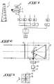
- - la figure 1 montre sous forme d'un schéma bloc le système de détection de sources de chaleur suivant la présente invention ;
- - la figure 2 montre de façon schématique et à plus grande échelle l'ensemble détecteur représenté à la figure 1 ;
- - la figure 3 est une vue de dessus sur le détecteur représenté sur la figure 2 ;
- - la figure 4 montre de façon schématique et à plus grande échelle un autre mode de réalisation de l'ensemble détecteur représenté à la figure 1 ;
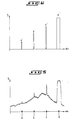
- - les figures 5 et 6 montrent respectivement le signal de sortie produit par le détecteur avant et après une opération de mise en forme, en fonction de la position angulaire du détecteur ;
- - la figure 7 illustre le principe de structure et de fonctionnement du système suivant la présente invention, sous forme d'un schéma bloc ; et
- - les figures 8 et 9 illustrent schématiquement la structure des octets transmis au poste central.
- - Figure 1 shows in the form of a block diagram the heat source detection system according to the present invention;
- - Figure 2 shows schematically and on a larger scale the detector assembly shown in Figure 1;
- - Figure 3 is a top view on the detector shown in Figure 2;
- - Figure 4 shows schematically and on a larger scale another embodiment of the detector assembly shown in Figure 1;
- - Figures 5 and 6 respectively show the output signal produced by the detector before and after a shaping operation, depending on the angular position of the detector;
- - Figure 7 illustrates the principle of structure and operation of the system according to the present invention, in the form of a block diagram; and
- - Figures 8 and 9 schematically illustrate the structure of the bytes transmitted to the central station.
Le procédé et le système selon la présente invention sont particulièrement appropriés pour détecter des sources de chaleur telles que des incendies dans des forêts de grande étendue. Il est donc avantageux de décrire l'invention en prenant comme exemple d'application un système de surveillance des forêts tel qu'il est représenté à la figure 1. Il est à noter que l'invention n'est cependant nullement limitée à une telle application et est utilisable dans tout cas où il s'agit de détecter et localiser dans une zone prédéterminée l'apparition d'un objet ou d'un phénomène, mobile ou immobile, qui émet des rayonnements infrarouges.The method and system according to the present invention are particularly suitable for detecting heat sources such as fires in large forests. It is therefore advantageous to describe the invention by taking as an application example a forest monitoring system as shown in FIG. 1. It should be noted that the invention is however in no way limited to such a application and can be used in any case where it is a question of detecting and locating in a predetermined area the appearance of an object or a phenomenon, mobile or immobile, which emits infrared radiation.
Le mode de réalisation de l'invention, représenté à la figure 1, pour la détection d'incendies de forêts, comprend un certain nombre de tours de surveillance dont une seule est représentée. Ces tours ont une hauteur suffisante et sont placées de façon appropriée pour que leur sommet soit situé à un niveau au-dessus des foyers d'incendie éventuels à détecter dans la zone forestière surveillée.The embodiment of the invention, represented in FIG. 1, for the detection of forest fires, comprises a certain number of surveillance towers of which only one is represented. These towers are of sufficient height and are appropriately placed so that their top is located at a level above any fire sources to be detected in the monitored forest area.
Au sommet de ces tours 1 est installé un équipement comprenant notamment un ensemble capteur-détecteur de rayonnements infrarouges 2, rotatif autour d'un axe sensiblement vertical pour pouvoir effectuer un mouvement de balayage horizontal, un codeur optique 3 associé à cet ensemble et destiné à déterminer les positions angulaires de ce dernier, un dispositif de traitement 4 des signaux produits par le détecteur et représentatif de l'intensité des rayonnements infrarouges captés, ainsi qu'un modem 5 relié à une ligne téléphonique 6 et destiné à adapter les signaux électriques aux propriétés de la ligne téléphonique.At the top of these
Des lignes téléphoniques comme la ligne 6 relient les différents postes de surveillance en haut des tours 1 à un poste central 7, avantageusement un ordinateur, par l'intermédiaire de modems 8 et de multiplexeurs à huit canaux 9, chacun associé à huit modems. Le chiffre de référence 10 désigne un dispositif de stockage et d'archivage associé à l'ordinateur 7.Telephone lines such as
Il est à noter que la liaison par ligne téléphonique du poste central aux différents postes de surveillance pourrait être remplacée par tout autre moyen de communication. Bien entendu, le type de liaison devrait être choisi en fonction de l'infrastructure déjà en place ou pouvant être installée, facilement et de façon économique.It should be noted that the telephone line link from the central station to the various surveillance stations could be replaced by any other means of communication. Of course, the type of link should be chosen according to the infrastructure already in place or which can be installed, easily and economically.
En se reportant aux figures 2 et 3 on décrira ci-après de façon plus détaillée l'ensemble capteur-détecteur de rayonnements infrarouges 2.Referring to Figures 2 and 3 we will describe below after in more detail the sensor-detector assembly of
Cet ensemble 2 comprend un dispositif optique collecteur de rayonnement, pourvu d'un filtre infrarouge 12, d'un miroir sphérique collecteur 13 et du détecteur proprement dit 14 qui est pourvu d'une fenêtre 15 de forme rectangulaire suivant la figure 3. L'ensemble entouré sur la figure 2 par une ligne en traits interrompus est rotatif autour d'un axe vertical centré sur le centre de la fente 15 et sur le détecteur situé en dessous et fixe. Cet ensemble est entraîné en rotation par un moteur pas-à-pas 16 suivant le sens de rotation indiqué en 17 pour pouvoir ainsi effectuer le mouvement de balayage horizontal. La fente 15 qui fait partie de l'ensemble rotatif est représentée en pointillés dans plusieurs positions angulaires au-dessus de la surface sensible fixe 18 du détecteur 14.This
Pour permettre un balayage du champ vertical, un miroir vibrant 20 est disposé dans l'ensemble rotatif dans la zone focale de l'optique collectrice 13 de façon à déplacer l'image du détecteur dans le plan focal image de cette optique ou, autrement dit, de façon à former sur le détecteur fixe 14 l'image d'une partie du champ vertical. Ce miroir vibre à une fréquence relativement élevée pour des raisons qui seront expliquées plus loin.To allow scanning of the vertical field, a vibrating
En figure 3, on reconnaît le codeur optique angulaire destiné à définir la position angulaire de l'ensemble rotatif lors du balayage du champ horizontal.In FIG. 3, the angular optical encoder intended to define the angular position of the rotary assembly can be recognized during the scanning of the horizontal field.
Avant d'expliquer le fonctionnement du système et des différentes opérations du procédé pour la détection d'un incendie, englobant un traitement spécifique des signaux produits par le détecteur, on donnera ci-après quelques considérations qui permettent de comprendre selon quels critères le détecteur et le dispositif optique et mécanique ainsi que le dispositif de traitement de signaux pourraient être avantageusement choisis. L'objectif du système selon la présente invention, donné uniquement à titre d'exemple, est de détecter des incendies de forêts jusqu'à des distances pouvant atteindre 20 km. Il importe que l'information, c'est-à-dire le rayonnement émis par un feu, se transmette jusqu'au détecteur avec le minimum d'absorption. En tenant compte du spectre d'absorption de l'atmosphère du rayonnement infrarouge, on constate l'existence d'un certain nombre de bandes spectrales ou fenêtres particulièrement transparentes à ce rayonnement. Dans le cadre de l'invention, on retient comme fenêtres la bande de longueurs d'onde allant de 3 à 5,5 ""m. Dans cette bande la transmission atmosphérique est bonne et le rayonnement parasite tel que par exemple le rayonnement solaire est limité. Cette fenêtre s'est avérée avantageuse pour une surveillance optimale 24 heures sur 24, donc même en plein jour. Les détecteurs qui sont efficaces dans ce domaine de longueurs d'onde sont par exemple des détecteurs en PbSe, refroidis à -45 °C. Il est cependant à noter que le choix du détecteur de rayonnement infrarouge est fonction des conditions et critères spécifiques de chaque cas d'application.Before explaining the operation of the system and the various operations of the process for detecting a fire, including a specific processing of the signals produced by the detector, some considerations will be given below which make it possible to understand according to which criteria the detector and the optical and mechanical device as well as the signal processing device could be advantageously chosen. The objective of the system according to the present invention, given by way of example only, is to detect forest fires up to distances of up to 20 km. It is important that the information, that is to say the radiation emitted by a fire, is transmitted to the detector with the minimum of absorption. By taking into account the absorption spectrum of the atmosphere of infrared radiation, we note the existence of a certain number of spectral bands or windows which are particularly transparent to this radiation. In the context of the invention, the band of wavelengths ranging from 3 to 5.5 "" m is used as windows. In this band the atmospheric transmission is good and the stray radiation such as for example the solar radiation is limited. This window proved to be advantageous for
Dans le cadre de l'invention, on cherche par exemple à obtenir une résolution spatiale qui est de l'ordre de 15 mètres à 20 km de distance. Il convient donc de pouvoir opérer à 15 m près à 20 km un foyer d'incendie. Or, à 20 km un segment de 15 m est vu sous un angle 2ah = 15/2 x 104 rds = 7,7 x 10- radians. Le nombre de secteurs élémentaires résolus pour chaque tour sera donc de Za/2ah = 8192 secteurs = 213.In the context of the invention, it is sought for example to obtain a spatial resolution which is of the order of 15 meters to 20 km away. It is therefore advisable to be able to operate within 15 m to 20 km of a fire. However, at 20 km a segment of 15 m is seen at an angle 2a h = 15/2 x 10 4 rds = 7.7 x 10- radians. The number of elementary sectors resolved for each turn will therefore be Za / 2ah = 8192 sectors = 2 13 .
Le codeur optique prévu pour la définition des positions angulaires du système optique rotatif doit donc être capable de différencier 213 directions différentes par tour.The optical encoder provided for defining the angular positions of the rotary optical system must therefore be able to differentiate 2 13 different directions per revolution.
Pour des raisons liées à la cadence maximale de transmission des lignes téléphoniques habituelles, et au nombre d'informations utiles à transmettre, la vitesse la plus rapide d'analyse de l'horizon correspondra avantageusement à un tour en 40 secondes. Le temps d'analyse d'un secteur est donc de 5 ms environ correspondant à une fréquence de 200 Hz. Pour avoir une bonne résolution spatiale il est avantageux que le détecteur ait une bande passante environ 10 fois supérieure c'est-à-dire d'environ 2 kHz.For reasons related to the maximum rate of transmission of usual telephone lines, and to the number of useful information to be transmitted, the fastest speed of analysis of the horizon will advantageously correspond to one revolution in 40 seconds. The analysis time of a sector is therefore approximately 5 ms corresponding to a frequency of 200 Hz. To have good spatial resolution it is advantageous for the detector to have a bandwidth approximately 10 times greater, that is to say about 2 kHz.
Concernant le champ d'observation vertical et notamment de la fréquence du balayage vertical, il convient de tenir compte de ce qui suit : si les tours d'observation présentent une altitude de 40 m et si la limite supérieure du champ d'observation verticale est la direction horizontale, ce qui permet d'éviter d'être en observation directe du soleil, sauf le matin et le soir, et en prenant comme limite inférieure une zone d'ombre de 200 m autour du pied de la tour, on obtient un angle de champ vertical égal à 15 x 10-2 rds. Il est à noter que cette zone d'ombre est relative, car tout feu qui y naîtrait sera immédiatement détecté à cause des fumées qui traverseraient la zone d'observation, à une distance très proche du système de détection. En raison de la disproportion entre les champs vertical et horizontal et des exigences qui en découlent pour les dimensions du détecteur, il est avantageux d'associer au détecteur le miroir vibrant 20. Comme il a été dit plus haut, ce miroir vibre avantageusement à une fréquence suffisamment élevée pour que le détecteur semble voir tout le champ angulaire vertical en une seule fois. Il est alors avantageux de choisir une fréquence de vibration de l'ordre de 20 kHz, c'est-à-dire 100 fois plus élevée que la fréquence d'analyse d'un secteur horizontal et 10 fois plus élevée que la limite supérieure de la bande passante du système de détection (2 kHz).Regarding the vertical observation field and in particular the frequency of vertical scanning, the following should be taken into account: if the observation towers have an altitude of 40 m and if the upper limit of the vertical observation field is the horizontal direction, which avoids being in direct observation of the sun, except in the morning and in the evening, and taking as a lower limit a shadow zone of 200 m around the foot of the tower, we obtain a vertical field angle equal to 15 x 10- 2 rds. It should be noted that this gray area is relative, because any fire which would be born there will be immediately detected because of the fumes which would cross the observation area, at a distance very close to the detection system. Due to the disproportion between the vertical and horizontal fields and the resulting requirements for the dimensions of the detector, it is advantageous to associate the detector with the vibrating
Il est cependant à noter que l'utilisation d'un miroir vibrant pour effectuer un balayage vertical n'est pas obligatoire et pourrait être supprimée si le champ vertical est suffisamment faible ou la surface sensible du détecteur est suffisamment importante. Tout autre moyen approprié pourrait d'ailleurs être utilisé pour remédier aux problèmes de disproportion susmentionnés.It should however be noted that the use of a vibrating mirror to perform a vertical scan is not compulsory and could be eliminated if the vertical field is sufficiently weak or the sensitive surface of the detector is sufficiently large. Any other appropriate means could also be used to remedy the problems of disproportion mentioned above.
La figure 4 représente un autre mode de réalisation de l'ensemble capteur-détecteur de rayonnements infrarouges 2. Celui-ci comprend un dispo; . sitif optique collecteur de rayonnement, pourvu du filtre infrarouge 12, d'un dispositif 13a formant objectif et du détecteur 14 pourvu de la fenêtre 15. Comme pour l'autre mode de réalisation des figures 2 et 3, l'ensemble entouré sur la figure 4 et par une ligne en traits interrompus est rotatif autour d'un axe vertical centré sur le centre de la fente 15 et sur le détecteur 14 situé en dessous et fixe. Cet ensemble est entraîné en rotation de la même façon que celui de la figure 2 de sorte que le moyen d'entraînement 16 a été omis en figure 4. Pour permettre le balayage du champ vertical, un miroir tournant 20a suivant le sens des aiguilles d'une montre est disposé dans l'ensemble rotatif dans la zone focale de l'objectif 13a de façon à former sur le détecteur fixe 14 l'image d'une partie du champ vertical. Le miroir 20a comporte plusieurs surfaces réfléchissantes 20,1-20,8 disposées par exemple en octogone et focalise le rayonnement infrarouge sur le détecteur 14 via la lentille convergente 13b située au-dessus du détecteur 14 et de la fente 15. Le miroir tourne autour de l'axe passant par le centre 0 de l'octogone et perpendiculaire par rapport à l'axe en traits mixtes passant par les centres de la lentille 13b, de la fente 15, et du détecteur 14. La vitesse angulaire de rotation du miroir 20a doit être choisie de manière à être suffisament élevée pour que le détecteur semble voir tout le champ angulaire vertical en une seule fois. Cette vitesse peut être choisie en concordance avec la fréquence de vibration du miroir 20 définie précédemment.FIG. 4 represents another embodiment of the sensor-detector assembly for
Le procédé et le fonctionnement du système selon l'invention, qui vient d'être décrit, ressort de la description du fonctionnement qui sera faite ci-après en se reportant aux figures 5 à 9. Le détecteur 2 émet un signal électrique directement proportionnel à l'intensité des rayonnements infrarouges reçus. Ce signal est transmis au dispositif de traitement 4 dans lequel il est amplifié en 22, mis en forme en 23, converti en 24 sous forme numérique par un convertisseur analogique-numérique et traité dans un circuit de traitement logique et de contrôle de transmission 25, avant de parvenir au modem 5, comme cela ressort de la figure 8.The method and the operation of the system according to the invention, which has just been described, appears from the description of the operation which will be given below with reference to FIGS. 5 to 9. The
A titre d'exemple, la figure 5 montre le signal électrique de sortie du détecteur 2 en fonction de la position angulaire OEH de l'ensemble optique rotatif du détecteur, au cours du balayage du champ horizontal. Ce signal présente en a, b et c des crêtes qui sont représentatives respectivement d'un feu de 5 m à 20 km, de 5 m à 15 km et de 5 m à 5 km. La montée brusque en d du niveau du signal de sortie est provoquée par le soleil. La distinction entre des sources de chaleur devant être repérées, comme les foyers de feu a, b et c, de la source de chaleur d et d'autres encore, s'effectuera dans le poste central à la manière qui sera décrite plus loin. En considérant les crêtes représentatives d'un feu, sur la figure 5, on constate que ces crêtes se caractérisent moins par leur amplitude par rapport au fond parasite- amplitude qui peut être relativement faible comme dans le cas de la crête a - mais plutôt par la forme de ces crêtes qui se distingue par des flancs avant et arrière très raides, c'est-à-dire des temps de montée très courts.By way of example, FIG. 5 shows the electrical output signal from the
En tirant profit de cette particularité, on obtient à la sortie du circuit de mise en forme 23 les impulsions a', b', et c' et d' (figure 6), qui correspondent aux crêtes a, b, c et d. Le convertisseur analogique-numérique 24 convertit chaque impulsion qui contient l'information de l'intensité d'un rayonnement infrarouge émis par la source de chaleur en un signal numérique à 8 bits.By taking advantage of this feature, we obtain at the output of the shaping
Le module de traitement logique et de contrôle de transmission 25 reçoit pour chaque source de chaleur le signal numérique relatif à l'intensité du rayonnement et l'information correspondante relative à la position angulaire de l'ensemble optique rotatif, qui a été généré par le codeur optique 3 sous forme d'un signal numérique à 13 bits ; si chaque position angulaire correspond à un segment angulaire de 2ah = 7,7 x 10⁻⁴ radians comme dans le présent exemple. Le module 25 ordonne tout d'abord les signaux pour qu'ils soient transmissibles par le modem 5. Du fait que le modem n'accepte que des signaux à 8 bits en série, le module 25 combine les deux informations respectivement de 13 bits parallèles et de 8 bits parallèles en une information de 8 bits série. Les figures 8 et 9 illustrent la structure des octets d'information transmis par le modem 5 au poste central 7 (figure 1). Par conséquent, il convient que le module 25 effectue une compression d'informations. Celle-ci consiste tout d'abord à ne pas transmettre les 13 bits de position angulaire. Dans le train de 8 bits envoyé au modem 5, on utilise qu'un bit pour le repérage de position. Celui-ci est un bit de synchronisation qui est toujours à l'état logique bas « 0 •, sauf au moment du passage à la position angulaire numérique 0000000000000 où le signal de synchronisation est au niveau logique haut « 1 Ce bit permet la reconstitution de l'information relative à la position angulaire dans le poste central. Ce dernier comprend à cette fin un compteur 13 bits qui est remis à zéro par le bit de synchronisation et qui est incrémenté d'un pas à chaque nouvelle transmission d'un octet. Pour ce qui est des données de niveau d'intensité de rayonnement, la précision de 8 bits n'est pas nécessaire et on se contente d'une précision de 3 bits. On peut donc envoyer à l'aide d'un octet les informations relatives à deux positions angulaires du capteur du détecteur, formé par l'ensemble optique rotatif. Le compteur 13 bits du poste central, c'est-à-dire de l'ordinateur 7, est par conséquent incrémenté de deux pas à chaque nouvelle transmission d'un octet. Le bit restant de l'octet est utilisé pour une indication du bon fonctionnement de tous les systèmes installés sur la tour 2. Les figures 8 et 9 représentent deux octets transmis successivement. La configuration de chaque octet représenté est caractérisée par un bit Do de synchronisation, un bit D, d'erreur, 3 bits D2 à D4 de données d'intensité de rayonnement relative à une position angulaire n (figure 8) ou n + 2 (figure 9) et 3 bits D5 à D7 de données d'intensité respectives à la position angulaire suivante n + 1 (figure 8) ou n + 3 (figure 9).The logic processing and
Chaque octet ainsi formé est transmis au modem 5 qui l'envoie au modem 8 par la ligne téléphonique permanente 6. En sortie du modem 8, l'octet est mémorisé dans l'ordinateur du poste central 7. Il est ensuite ré-injecté par l'ordinateur dans le modem 8 qui le retransmet au modem 5 pour aboutir au module de traitement 25. Ce dernier compare ensuite l'octet de départ et l'octet de retour. Si les deux octets sont équivalents, la transmission s'est bien faite et l'ordinateur a mémorisé des données justes. Si les deux octets sont différents, il y a eu erreur de transmission et l'ordinateur a mémorisé des données fausses. Une fois la comparaison des deux octets achevée, le module de traitement logique de contrôle de transmission 25 agit sur la commande du moteur pas-à-pas 16 d'entraînement du capteur formé par l'ensemble optique rotatif du détecteur 2. Si le capteur se trouvait lors de la comparaison dans la position n + 1, le moteur place le capteur maintenant en position n + 2. Le capteur produit un nouveau signal de sortie qui sera traité par le circuit de mise en forme 23, après amplification en 22, et appliqué au convertisseur analogique-numérique 24. Le module 25 déclenche alors la conversion analogique-numérique et mémorise l'octet d'intensité de rayonnement relative à la position n + 2. Ensuite, le module 25 agit à nouveau sur la commande de rotation du moteur 16, pour placer le capteur dans la position n + 3. Il déclenche une nouvelle conversion analogique-numérique, puis à partir des nouvelles données enregistrées, envoie au modem 5 l'octet n + 2, n + 3 suivant la figure 9. Cet octet contient dans le bit D, l'information relative à la comparaison de l'octet transmis auparavant contenant les informations relatives aux positions angulaires n et n + 1 (figure 8). Si l'opération de comparaison antérieure a trouvé une erreur de transmission, le bit d'erreur du nouveau octet est à l'état logique haut « 1 » ce qui provoque l'invalidation de l'octet (n, n + 1) précédemment enregistrée par l'ordinateur.Each byte thus formed is transmitted to the
Les opérations qui viennent d'être décrites permettent une vérification permanente du bon fonctionnement du système. On décrira ci-après l'opération importante qui permet de détecter un feu d'autres sources de chaleur, qui ne doivent pas donner lieu au déclenchement d'une alarme. En effet, d'autres sources de chaleur pourraient provoquer la production de signaux semblables aux crêtes indicatrices d'un feu, qui ont été indiquées à la figure 5. Par exemple, la variation brusque de niveau de signal d, qui est engendrée par le soleil (lever ou coucher du soleil) et indiquée au module 25 sous forme de l'impulsion d' est transmis au poste central ou l'ordinateur 7. De même des fumées d'habitat et dans certains cas les voitures automobiles, les trains, les avions etc.... situés habituellement ou traversant la zone surveillée par le détecteur 2 seraient portés à la connaissance de l'ordinateur 7. Pour éliminer un déclenchement non justifié d'une alarme, on a répertorié dans le poste central 7 les sources de chaleur parasites qui ne doivent pas être prises en compte. A cette fin, l'ordinateur du poste central est pourvu d'une mémoire dans laquelle les informations relatives à des sources ont été enregistrées. Pour savoir si une source de chaleur repérée par le détecteur 2 est un feu, l'ordinateur effectue à la suite de la réception de chaque octet, après avoir associé à l'information reçue l'information relative à la position angulaire du capteur du détecteur, à l'aide de son compteur de 13 bits et le bit de synchronisation Do contenu dans l'octet reçu, une comparaison au contenu de sa mémoire.The operations which have just been described allow a permanent verification of the proper functioning of the system. An important operation will be described below which makes it possible to detect a fire from other heat sources, which must not give rise to the triggering of an alarm. Indeed, other sources of heat could cause the production of signals similar to the peaks indicative of a fire, which have been indicated in FIG. 5. For example, the sudden change in signal level d, which is generated by the sun (sunrise or sunset) and indicated in
Il est ainsi aisé de distinguer un feu de source de chaleur 'parasite immobile. Pour permettre également la distinction d'un feu d'une source de chaleur parasite mais mobile ou passagère, telle qu'une voiture automobile ou un train, le fait que cette source se déplace peut servir de critère de distinction. Une programmation appropriée de l'ordinateur permet ainsi à l'ordinateur la détection d'un feu, même vis-à-vis de sources de chaleur parasites mobiles.It is thus easy to distinguish an immobile parasitic heat source fire. To also allow the distinction of a fire from a parasitic but mobile or transient heat source, such as a car or a train, the fact that this source moves can serve as a criterion for distinction. Appropriate programming of the computer thus allows the computer to detect a fire, even vis-à-vis mobile stray heat sources.
Il ressort de la description du système conforme à l'invention, qui vient d'être faite, que le poste central 7 ou plus exactement l'ordinateur reçoit de façon permanente un flux d'informations provenant des différents postes de surveillance chacun équipé d'un détecteur de rayonnement infrarouge. Si une source de chaleur s'avère être un feu, celui-ci peut être facilement localisé dès sa naissance et des mesures peuvent être prises immédiatement pour éteindre ce début d'incendie.It appears from the description of the system according to the invention, which has just been made, that the
Bien entendu, l'invention n'est nullement limitée à la détection d'un feu. De façon générale, l'invention peut être utilisée pour détecter l'apparition ou la pénétration dans une zone surveillée de tout objet ou phénomène donnant lieu à l'émission d'un rayonnement infrarouge. L'invention pourrait ainsi servir pour surveiller par exemple une frontière.Of course, the invention is in no way limited to the detection of a fire. In general, the invention can be used to detect the appearance or penetration into a monitored area of any object or phenomenon giving rise to the emission of infrared radiation. The invention could thus be used to monitor, for example, a border.
Il est encore à ajouter que les informations relatives à la nature du détecteur, au mode de vérification du bon fonctionnement du système et à la configuration des messages sous forme numérique pourraient être différentes sans sortir du cadre de l'invention.It should also be added that the information relating to the nature of the detector, to the mode of verification of the proper functioning of the system and to the configuration of the messages in digital form could be different without departing from the scope of the invention.
On pourrait également prévoir que le capteur de rayonnement effectue un mouvement pas-à-pas de balayage vertical et transmette au poste central des informations relatives à la position dans le champ vertical. Dans le poste on pourrait ainsi localiser la source du rayonnement à partir des données relatives aux positions dans les champs horizontal et vertical.Provision could also be made for the radiation sensor to perform a vertical scanning step-by-step movement and transmit information relating to the position in the vertical field to the central station. In the station we could thus locate the source of the radiation from the data relating to the positions in the horizontal and vertical fields.
Claims (17)
Priority Applications (1)
| Application Number | Priority Date | Filing Date | Title |
|---|---|---|---|
| AT84400030T ATE41539T1 (en) | 1983-01-13 | 1984-01-06 | METHOD FOR DETECTING A HEAT SOURCE, IN PARTICULAR FOREST FIRE, IN A MONITORED ZONE AND SYSTEM FOR CARRYING OUT THESE METHOD. |
Applications Claiming Priority (2)
| Application Number | Priority Date | Filing Date | Title |
|---|---|---|---|
| FR8300461A FR2541484B1 (en) | 1983-01-13 | 1983-01-13 | METHOD FOR THE DETECTION OF A SOURCE OF HEAT IN PARTICULAR OF A FOREST FIRE IN A MONITORED AREA, AND SYSTEM FOR CARRYING OUT SAID METHOD |
| FR8300461 | 1983-01-13 |
Publications (2)
| Publication Number | Publication Date |
|---|---|
| EP0117162A1 EP0117162A1 (en) | 1984-08-29 |
| EP0117162B1 true EP0117162B1 (en) | 1989-03-15 |
Family
ID=9284902
Family Applications (1)
| Application Number | Title | Priority Date | Filing Date |
|---|---|---|---|
| EP84400030A Expired EP0117162B1 (en) | 1983-01-13 | 1984-01-06 | Method for the detection of a heat source particularly of a forest fire in a controlled zone, and system for the application of this method |
Country Status (11)
| Country | Link |
|---|---|
| US (1) | US4567367A (en) |
| EP (1) | EP0117162B1 (en) |
| AT (1) | ATE41539T1 (en) |
| AU (1) | AU576746B2 (en) |
| CA (1) | CA1229143A (en) |
| DE (1) | DE3477285D1 (en) |
| ES (1) | ES8407349A1 (en) |
| FR (1) | FR2541484B1 (en) |
| GR (1) | GR79473B (en) |
| MA (1) | MA20004A1 (en) |
| PT (1) | PT77948B (en) |
Families Citing this family (26)
| Publication number | Priority date | Publication date | Assignee | Title |
|---|---|---|---|---|
| FR2572564B1 (en) * | 1984-10-30 | 1986-12-19 | Macron Patrick | ELECTRONIC DEVICE FOR MONITORING AND CONTROLLING INTRUSION |
| GB2171513B (en) * | 1985-02-19 | 1989-08-31 | Atomic Energy Authority Uk | Safety system for laser-utilising facilities |
| US4845629A (en) * | 1985-07-18 | 1989-07-04 | General De Investigacion Y Desarrollo S.A. | Airport surveillance systems |
| AU587447B2 (en) * | 1986-04-25 | 1989-08-17 | Hochiki Kabushiki Kaisha | Scanning fire-monitoring system |
| EP0298182A1 (en) * | 1987-05-06 | 1989-01-11 | Societe Industrielle D'aviation Latecoere | Fire detection method and device |
| FR2598238A1 (en) * | 1986-05-05 | 1987-11-06 | Latecoere Ste Indle Aviat | Method and device for detecting fires |
| IT1206251B (en) * | 1987-02-19 | 1989-04-14 | Teletron Srl | VISIBLE AND / OR INFRARED CONTROL SYSTEM PARTICULARLY SUITABLE FOR FIRE PREVENTION |
| FR2614984A1 (en) * | 1987-05-05 | 1988-11-10 | Argamakoff Aleksy | Automatic forest fire detector |
| FR2637977B1 (en) * | 1988-10-13 | 1992-03-13 | Brown De Colstoun Francois | METHOD AND SYSTEM FOR DETECTION IN PARTICULAR OF FOREST FIRE |
| US4975584A (en) * | 1989-03-29 | 1990-12-04 | Mountain Ocean, Ltd. | Method and apparatus for collecting, processing and displaying ultraviolet radiation data |
| GR890100820A (en) * | 1989-12-13 | 1992-05-12 | Alexiou Apostolos D | Automatic system for teledetecting fire and transmission of in formation |
| FR2669455B1 (en) * | 1990-11-21 | 1993-01-08 | Dassault Electronique | AIR AND / OR TERRESTRIAL REMOTE DETECTION INSTALLATION, PARTICULARLY FOR THE DETECTION OF FOREST FIRES. |
| FR2671196B1 (en) * | 1990-12-27 | 1994-05-06 | Sopelem | TELEMETRIC DEVICE FOR THE DETECTION AND LOCATION OF OBJECTS OR BACK-DIFFUSING SUBSTANCES. |
| US5160842A (en) * | 1991-06-24 | 1992-11-03 | Mid-Valley Helicopters, Inc. | Infrared fire-perimeter mapping |
| IL105772A (en) | 1992-06-01 | 1998-07-15 | Univ Florida | Methods and materials for combating pests |
| ES2070710B1 (en) * | 1993-02-10 | 1997-05-01 | Nacional Bazan De Construccion | SURVEILLANCE SYSTEM AND DETECTION OF HEAT SPOTS IN OPEN AREAS. |
| US5534697A (en) * | 1994-09-02 | 1996-07-09 | Rockwell International Corporation | Electro-optical sensor system for use in observing objects |
| US5502309A (en) * | 1994-09-06 | 1996-03-26 | Rockwell International Corporation | Staring sensor |
| US5627675A (en) * | 1995-05-13 | 1997-05-06 | Boeing North American Inc. | Optics assembly for observing a panoramic scene |
| US5841589A (en) * | 1995-09-26 | 1998-11-24 | Boeing North American, Inc. | Panoramic optics assembly having an initial flat reflective element |
| US5815090A (en) * | 1996-10-31 | 1998-09-29 | University Of Florida Research Foundation, Inc. | Remote monitoring system for detecting termites |
| GB2348531A (en) * | 1999-02-17 | 2000-10-04 | Bambour Olubukola Omoyiola | Forest fire detector unit |
| US6404210B1 (en) | 1999-03-02 | 2002-06-11 | University Of Florida Research Foundation, Inc. | Dimensionally stable sensor for monitoring termite activity |
| ITRM20040245A1 (en) * | 2004-05-14 | 2004-08-14 | Gen Contractor S R L | METHOD FOR THE OPTIMIZED VOLUMETRIC DETECTION OF EVENTS ON A GEOGRAPHICAL AREA, APPARATUS USING SUCH METHOD AND RELATED DETECTION SYSTEM. |
| CN108520615B (en) * | 2018-04-20 | 2020-08-25 | 吉林省林业科学研究院 | Fire identification system and method based on image |
| CN112991657A (en) * | 2021-02-08 | 2021-06-18 | 四川省铭阳睿智科技有限公司 | Forest fire intelligent early warning control system based on 5G communication technology |
Citations (1)
| Publication number | Priority date | Publication date | Assignee | Title |
|---|---|---|---|---|
| US3924130A (en) * | 1968-02-12 | 1975-12-02 | Us Navy | Body exposure indicator |
Family Cites Families (8)
| Publication number | Priority date | Publication date | Assignee | Title |
|---|---|---|---|---|
| US1959702A (en) * | 1930-04-22 | 1934-05-22 | George A Barker | Apparatus for detecting forest fires |
| US3987445A (en) * | 1963-02-11 | 1976-10-19 | Fales Iii David | Oblique scatter object detection and location system |
| GB1127443A (en) * | 1965-01-13 | 1968-09-18 | Thring S Advanced Developments | Improvements in or relating to fire detection and fighting apparatus |
| GB1089757A (en) * | 1965-08-14 | 1967-11-08 | Thrings Advanced Developments | Improvements in or relating to fire detection, alarm, and fighting apparatus |
| US3475608A (en) * | 1967-11-02 | 1969-10-28 | Us Army | Thermal,moving target,intrusion detector |
| FR2224818A1 (en) * | 1973-04-05 | 1974-10-31 | Onera (Off Nat Aerospatiale) | Forest fire detection appts - responsive to visible or infra red radiation in area surrounding observation post |
| US3941923A (en) * | 1974-04-01 | 1976-03-02 | Hughes Aircraft Company | Thermal imaging system with redundant object space scanning |
| AU6594080A (en) * | 1980-01-19 | 1981-07-30 | W. Vinten Ltd. | Intruder alarm systems |
-
1983
- 1983-01-13 FR FR8300461A patent/FR2541484B1/en not_active Expired
-
1984
- 1984-01-06 EP EP84400030A patent/EP0117162B1/en not_active Expired
- 1984-01-06 DE DE8484400030T patent/DE3477285D1/en not_active Expired
- 1984-01-06 AT AT84400030T patent/ATE41539T1/en not_active IP Right Cessation
- 1984-01-09 AU AU23147/84A patent/AU576746B2/en not_active Ceased
- 1984-01-09 CA CA000444895A patent/CA1229143A/en not_active Expired
- 1984-01-10 GR GR73459A patent/GR79473B/el unknown
- 1984-01-11 MA MA20225A patent/MA20004A1/en unknown
- 1984-01-12 US US06/570,198 patent/US4567367A/en not_active Expired - Lifetime
- 1984-01-12 PT PT77948A patent/PT77948B/en not_active IP Right Cessation
- 1984-01-12 ES ES528840A patent/ES8407349A1/en not_active Expired
Patent Citations (1)
| Publication number | Priority date | Publication date | Assignee | Title |
|---|---|---|---|---|
| US3924130A (en) * | 1968-02-12 | 1975-12-02 | Us Navy | Body exposure indicator |
Also Published As
| Publication number | Publication date |
|---|---|
| MA20004A1 (en) | 1984-10-01 |
| FR2541484A1 (en) | 1984-08-24 |
| CA1229143A (en) | 1987-11-10 |
| AU2314784A (en) | 1984-07-19 |
| PT77948A (en) | 1984-02-01 |
| PT77948B (en) | 1986-04-10 |
| ES528840A0 (en) | 1984-09-16 |
| GR79473B (en) | 1984-10-30 |
| FR2541484B1 (en) | 1986-06-13 |
| DE3477285D1 (en) | 1989-04-20 |
| US4567367A (en) | 1986-01-28 |
| ES8407349A1 (en) | 1984-09-16 |
| ATE41539T1 (en) | 1989-04-15 |
| EP0117162A1 (en) | 1984-08-29 |
| AU576746B2 (en) | 1988-09-08 |
Similar Documents
| Publication | Publication Date | Title |
|---|---|---|
| EP0117162B1 (en) | Method for the detection of a heat source particularly of a forest fire in a controlled zone, and system for the application of this method | |
| EP1364351B1 (en) | Method and device for detecting fires based on image analysis | |
| EP0364364B1 (en) | Method and system for the detection of forest fires in particular | |
| EP0379425B1 (en) | System for determining the position of at least one target by means of triangulation | |
| EP0494815B1 (en) | Motor vehicles traffic measuring system | |
| EP0146428A1 (en) | Automatic guiding method and apparatsu for moving objects especially for driverless self-propelled vehicles | |
| FR2476325A1 (en) | OMNIDIRECTIONAL TRACKING SYSTEM FOR MOVING OBJECTS | |
| EP0241374B1 (en) | Optronic off-bore sight system for the spatial and spectral discrimination of infrared light sources | |
| WO1994008660A1 (en) | Process and device for the speedy and automatic detection of forest fires | |
| EP0234164B1 (en) | Station and device using the back-scattering of a laser beam for detecting and localizing an object or a substance such as smoke from a fire | |
| FR2608777A1 (en) | DEVICE FOR DETECTION OF INTRUSION AND RECOGNITION OF TERRESTRIAL VEHICLES | |
| EP0432025B1 (en) | Optical system for message transmission | |
| FR2535466A1 (en) | Method and apparatus for locating observation devices | |
| FR2675610A1 (en) | METHOD AND INSTALLATION FOR EVALUATING A TRAFFIC FLOW OF ROAD VEHICLES. | |
| CA2666030A1 (en) | Method and device for detecting an object that can retroreflect light | |
| FR2684763A1 (en) | INTEGRATED DEVICE FOR DETECTING AND IDENTIFYING OBSTACLES ON BOARD, IN PARTICULAR ON BOARD OF A MOTOR VEHICLE. | |
| FR2751479A1 (en) | METHOD AND SYSTEM FOR PROTECTING OPTRONIC STANDBY OR TRACKING EQUIPMENT WITH REGARD TO ILLUMINATION | |
| FR2474208A1 (en) | IMPROVEMENTS ON INTRUDER ALARM DEVICES | |
| FR2612647A1 (en) | MODULATION DEVICE FOR A RADIATION DETECTOR DEVICE CAPTURING AN IMAGE FIELD | |
| EP1584079B1 (en) | Device for detecting an incident or the like on a traffic lane portion | |
| FR2643173A1 (en) | Automatic detector of break-in or fire at great distance | |
| FR2506329A1 (en) | Charge profile determination in a blast furnace - by optical methods using a laser | |
| EP4080177B1 (en) | Method and system for controlling the maximum noise level related to the movement of a vehicle | |
| EP0528077A1 (en) | Airborne radar system with a camera for tracking low flying objects | |
| FR2588967A1 (en) | METHOD AND DEVICE FOR DETECTING HELICOPTERS |
Legal Events
| Date | Code | Title | Description |
|---|---|---|---|
| PUAI | Public reference made under article 153(3) epc to a published international application that has entered the european phase |
Free format text: ORIGINAL CODE: 0009012 |
|
| AK | Designated contracting states |
Designated state(s): AT BE CH DE GB IT LI LU NL SE |
|
| 17P | Request for examination filed |
Effective date: 19850222 |
|
| 17Q | First examination report despatched |
Effective date: 19860905 |
|
| GRAA | (expected) grant |
Free format text: ORIGINAL CODE: 0009210 |
|
| AK | Designated contracting states |
Kind code of ref document: B1 Designated state(s): AT BE CH DE GB IT LI LU NL SE |
|
| REF | Corresponds to: |
Ref document number: 41539 Country of ref document: AT Date of ref document: 19890415 Kind code of ref document: T |
|
| REF | Corresponds to: |
Ref document number: 3477285 Country of ref document: DE Date of ref document: 19890420 |
|
| ITF | It: translation for a ep patent filed |
Owner name: DE DOMINICIS & MAYER S.R.L. |
|
| GBT | Gb: translation of ep patent filed (gb section 77(6)(a)/1977) | ||
| PLBE | No opposition filed within time limit |
Free format text: ORIGINAL CODE: 0009261 |
|
| STAA | Information on the status of an ep patent application or granted ep patent |
Free format text: STATUS: NO OPPOSITION FILED WITHIN TIME LIMIT |
|
| 26N | No opposition filed | ||
| ITTA | It: last paid annual fee | ||
| EPTA | Lu: last paid annual fee | ||
| EAL | Se: european patent in force in sweden |
Ref document number: 84400030.7 |
|
| PGFP | Annual fee paid to national office [announced via postgrant information from national office to epo] |
Ref country code: GB Payment date: 19961230 Year of fee payment: 14 |
|
| PGFP | Annual fee paid to national office [announced via postgrant information from national office to epo] |
Ref country code: LU Payment date: 19970101 Year of fee payment: 14 |
|
| PGFP | Annual fee paid to national office [announced via postgrant information from national office to epo] |
Ref country code: DE Payment date: 19970113 Year of fee payment: 14 |
|
| PGFP | Annual fee paid to national office [announced via postgrant information from national office to epo] |
Ref country code: AT Payment date: 19970114 Year of fee payment: 14 |
|
| PGFP | Annual fee paid to national office [announced via postgrant information from national office to epo] |
Ref country code: SE Payment date: 19970115 Year of fee payment: 14 |
|
| PGFP | Annual fee paid to national office [announced via postgrant information from national office to epo] |
Ref country code: CH Payment date: 19970120 Year of fee payment: 14 |
|
| PGFP | Annual fee paid to national office [announced via postgrant information from national office to epo] |
Ref country code: NL Payment date: 19970130 Year of fee payment: 14 |
|
| PGFP | Annual fee paid to national office [announced via postgrant information from national office to epo] |
Ref country code: BE Payment date: 19970318 Year of fee payment: 14 |
|
| PG25 | Lapsed in a contracting state [announced via postgrant information from national office to epo] |
Ref country code: LU Free format text: LAPSE BECAUSE OF NON-PAYMENT OF DUE FEES Effective date: 19980106 Ref country code: GB Free format text: LAPSE BECAUSE OF NON-PAYMENT OF DUE FEES Effective date: 19980106 Ref country code: AT Free format text: LAPSE BECAUSE OF NON-PAYMENT OF DUE FEES Effective date: 19980106 |
|
| PG25 | Lapsed in a contracting state [announced via postgrant information from national office to epo] |
Ref country code: SE Free format text: LAPSE BECAUSE OF NON-PAYMENT OF DUE FEES Effective date: 19980107 |
|
| PG25 | Lapsed in a contracting state [announced via postgrant information from national office to epo] |
Ref country code: LI Free format text: LAPSE BECAUSE OF NON-PAYMENT OF DUE FEES Effective date: 19980131 Ref country code: CH Free format text: LAPSE BECAUSE OF NON-PAYMENT OF DUE FEES Effective date: 19980131 Ref country code: BE Free format text: LAPSE BECAUSE OF NON-PAYMENT OF DUE FEES Effective date: 19980131 |
|
| BERE | Be: lapsed |
Owner name: MOSCOVI MICHEL Effective date: 19980131 Owner name: MOSCOVI JEAN-CLAUDE MARIAN Effective date: 19980131 Owner name: LE SAIGE DE LA VILLESBRUNNE ARNAUD GERARD Effective date: 19980131 Owner name: CHAMBARET YVES Effective date: 19980131 Owner name: CHAMBARET JEAN-PAUL Effective date: 19980131 Owner name: BROWN DE COLSTOUN FRANCOIS PATRICE DIDIER Effective date: 19980131 |
|
| PG25 | Lapsed in a contracting state [announced via postgrant information from national office to epo] |
Ref country code: NL Free format text: LAPSE BECAUSE OF NON-PAYMENT OF DUE FEES Effective date: 19980801 |
|
| GBPC | Gb: european patent ceased through non-payment of renewal fee |
Effective date: 19980106 |
|
| REG | Reference to a national code |
Ref country code: CH Ref legal event code: PL |
|
| NLV4 | Nl: lapsed or anulled due to non-payment of the annual fee |
Effective date: 19980801 |
|
| PG25 | Lapsed in a contracting state [announced via postgrant information from national office to epo] |
Ref country code: DE Free format text: LAPSE BECAUSE OF NON-PAYMENT OF DUE FEES Effective date: 19981001 |
|
| EUG | Se: european patent has lapsed |
Ref document number: 84400030.7 |