US4567367A - Method for detecting a source of heat, more particularly a forest fire in a watched area, and system for carrying out said method - Google Patents
Method for detecting a source of heat, more particularly a forest fire in a watched area, and system for carrying out said method Download PDFInfo
- Publication number
- US4567367A US4567367A US06/570,198 US57019884A US4567367A US 4567367 A US4567367 A US 4567367A US 57019884 A US57019884 A US 57019884A US 4567367 A US4567367 A US 4567367A
- Authority
- US
- United States
- Prior art keywords
- heat
- detector
- information
- central station
- infra
- Prior art date
- Legal status (The legal status is an assumption and is not a legal conclusion. Google has not performed a legal analysis and makes no representation as to the accuracy of the status listed.)
- Expired - Lifetime
Links
- 238000000034 method Methods 0.000 title claims description 30
- 230000005855 radiation Effects 0.000 claims abstract description 45
- 230000005540 biological transmission Effects 0.000 claims abstract description 38
- 230000033001 locomotion Effects 0.000 claims abstract description 15
- 230000003287 optical effect Effects 0.000 claims description 16
- 238000006073 displacement reaction Methods 0.000 claims 2
- 230000010365 information processing Effects 0.000 claims 2
- 238000011144 upstream manufacturing Methods 0.000 claims 1
- 230000000737 periodic effect Effects 0.000 abstract description 2
- 238000001514 detection method Methods 0.000 description 3
- 238000007493 shaping process Methods 0.000 description 3
- 239000000779 smoke Substances 0.000 description 3
- 238000006243 chemical reaction Methods 0.000 description 2
- 238000010586 diagram Methods 0.000 description 2
- YBNMDCCMCLUHBL-UHFFFAOYSA-N (2,5-dioxopyrrolidin-1-yl) 4-pyren-1-ylbutanoate Chemical compound C=1C=C(C2=C34)C=CC3=CC=CC4=CC=C2C=1CCCC(=O)ON1C(=O)CCC1=O YBNMDCCMCLUHBL-UHFFFAOYSA-N 0.000 description 1
- 238000010521 absorption reaction Methods 0.000 description 1
- 238000000862 absorption spectrum Methods 0.000 description 1
- 238000004891 communication Methods 0.000 description 1
- 238000013144 data compression Methods 0.000 description 1
- 230000000694 effects Effects 0.000 description 1
- 230000004807 localization Effects 0.000 description 1
- 238000004519 manufacturing process Methods 0.000 description 1
- 230000003595 spectral effect Effects 0.000 description 1
- 230000009897 systematic effect Effects 0.000 description 1
- 230000007306 turnover Effects 0.000 description 1
Images


Classifications
-
- G—PHYSICS
- G08—SIGNALLING
- G08B—SIGNALLING OR CALLING SYSTEMS; ORDER TELEGRAPHS; ALARM SYSTEMS
- G08B17/00—Fire alarms; Alarms responsive to explosion
- G08B17/005—Fire alarms; Alarms responsive to explosion for forest fires, e.g. detecting fires spread over a large or outdoors area
-
- G—PHYSICS
- G08—SIGNALLING
- G08B—SIGNALLING OR CALLING SYSTEMS; ORDER TELEGRAPHS; ALARM SYSTEMS
- G08B17/00—Fire alarms; Alarms responsive to explosion
- G08B17/12—Actuation by presence of radiation or particles, e.g. of infrared radiation or of ions
Definitions
- the present invention has for a subject matter a method for detecting a source of heat which may occur in a predetermined area, zone or space, possibly of great extent, particularly a fire in a forest, and a system for carrying out the said method.
- the method and system used nowadays to this end may be summed up as follows.
- the present invention has as its purpose to provide a method and a system for detecting a source of heat, more particularly a fire, which does not suffer from the above mentioned drawbacks inherent in the known method and system.
- the invention therefore relates to a method for detecting sources of heat, more particularly fires in forests or the like, within an area, zone or space, more particularly of great extent, according to which said area is placed under watch from at least two watching stations, the information relating to a detected source of heat is transmitted to a central station through a transmission link such as a telephone link, and in this central station is located the source of heat according to the information received from the watching stations, said method being characterized in that the said area is watched by means of an infrared radiation detector at each watching station, said detector is caused to periodically and preferably permanently accomplish angular movements for scanning the area to be watched, the information relating to all the sources of heat detected is transmitted to the central station, and there is performed a comparison of the information received from the detector with the information previously stored in this station, relating to known sources of heat and not to be taken into account, in order to determine the newly born sources of heat.
- the detector is displaced in a step-by-step manner and the information received by the detector during each corresponding period of stoppage is transmitted to the central station.
- the detector is caused to accomplish a vertical scanning motion during each period of stoppage, about a horizontal axis, the scanning being advantageously performed at a high frequency.
- the method of the invention there is transmitted to the said central state an, in digital form, the information relating to the intensity of infrared radiation received during the period of stoppage after each step or after several steps, said information is stored at the central station and returned to the detecting device in which the information received from the center is compared with the information initially transmitted to the latter, and there is indicated to the central station, together with the following information, if appropriate, by a bit of 0 or 1 value, whether there was an equivalence between the information compared, and the information stored at the central station is invalidated in case of a difference.
- each information relating to the intensity of the infrared radiation data such as a synchronizing bit which is used at the central station to synchronize the attribution to the said received information, relating to the radiation, of the information relating to the corresponding angular position of the detector.
- the system for carrying out the method according to the present invention is characterized in that it comprises a certain number of watching stations distributed within the area or zone to be watched, comprising an infrared radiation detector placed at a level above the area to be watched and connected to a motor for imparting to the detector a periodic angular, step-by-step motion, and a device for logic processing of the information received by the detector and for transmission through the telephone link, and in that the central station is equipped with a data processing device comprising a memory in which are recorded or entered the sources of heat known in the area to be watched.
- the detector is provided with a means allowing a vertical scanning during each angular position corresponding to a step of the detector.
- the vertical scanning means is constituted by a mirror vibrating at a high frequency.
- FIG. 1 is a block diagram of the system for detecting sources of heat according to the present invention
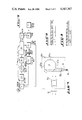
- FIG. 2 shows diagrammatically and to a larger scale the detector unit illustrated in FIG. 1;
- FIG. 3 is a top view of the detector illustrated in FIG. 2;
- FIG. 4 shows diagrammatically and to a larger scale another form of embodiment of the detector unit illustrated in FIG. 1;
- FIGS. 5 and 6 show the output signal produced by the detector before and after a shaping operation, respectively, depending on the angular position of the detector;
- FIG. 7 illustrates the structural and operating principle of the system of the present invention, in the form of a block diagram
- FIGS. 8 and 9 illustrate diagrammatically the structure of the octets transmitted to the central station.
- the method and system of the present invention are particularly suitable for detecting sources of heat such as fires in forests of great extent. It is therefore desirable to describe the invention by considering, as an example of application, a forest watching system such as the one illustrated in FIG. 1. It should be noted, however, that the invention is by no means limited to such an application and can be used in all cases where it is desired to detect and locate in a predetermined area the appearance of an object or of a phenomenon, either moving or fixed, which emits infrared radiation.
- FIG. 1 for detecting forest fires, comprises a certain number of watching towers, only one of which is shown. Such towers have sufficient height and are placed in a suitable manner so that their top is located at a level above the possible seats of fire to be detected in the watched forest area.
- an equipment comprising particularly an infrared radiation sensingdetecting assembly 2 rotatable about a substantially vertical axis so as to be capable of accomplishing a horizontal scanning motion, an optical coding device 3 associated with said assembly and intended to determine the angular positions of the latter, a device 4 for processing the signals produced by the detector and representing the intensity of the sensed infrared radiation, as well as a modem 5 connected to a telephone line 6 and intended to adapt the electric signals to the properties of the telephone line.
- an equipment comprising particularly an infrared radiation sensingdetecting assembly 2 rotatable about a substantially vertical axis so as to be capable of accomplishing a horizontal scanning motion, an optical coding device 3 associated with said assembly and intended to determine the angular positions of the latter, a device 4 for processing the signals produced by the detector and representing the intensity of the sensed infrared radiation, as well as a modem 5 connected to a telephone line 6 and intended to adapt the electric signals to the properties of the telephone line.
- the telephone lines such as the line 6 connect the watching stations at the top of towers 1 to a central station 7, which may advantageously comprise a computer, through the medium of modems 8 and of eight-channel multiplexers 9, each associated with 8 modems.
- the reference numeral 10 designates a storage and filing device associated with the central station 7.
- connection by a telephone line of the central station to the various watching stations may be replaced by any other means of communication.
- type of connection should be selected according to the infra-structure already installed or likely to be installed, easily and economically.
- the assembly 2 comprises an optical radiationcollecting device provided with an infrared filter 12, a spherical collecting mirror 13 and the detector proper 14 which is provided with an slit 15 of rectangular shape as seen in FIG. 3.
- the assembly surrounded in FIG. 2 with an interrupted line is rotatable about a vertical axis centered on the center of the slit 15 and on the detector fixedly located below.
- This assembly is driven in rotation by a step-by-step motor 16 in the direction of rotation indicated at 17 so as to be capable of accomplishing the horizontal scanning motion.
- the slit 15 pertaining to the rotatable assembly is shown in dotted lines in several angular positions about the stationary sensitive surface 18 of the detector 14.
- the vibrating mirror 20 is arranged in the rotatable assembly in the focal region of the collecting mirror 13 so as to displace the image of the detector in the image focal plane of the said mirror, or, otherwise stated, so as to form on the stationary detector 14 the image of a portion of the vertical field. Said mirror vibrates at a relatively high frequency for reasons which will be explained later.
- optical coding device intended to define the angular position of the rotatable assembly during the scanning of the horizontal field.
- the object of the system of the present invention is to detect forest fires at distances which may reach 20 kilometers. It is essential that the information, i.e. the radiation emitted by a fire, be transmitted to the detector with a minimum absorption. Taking into account the absorption spectrum of the atmosphere of the infrared radiation, it is found that there exists a certain number of spectral bands or windows which are particularly transparent to this radiation.
- the window is taken to be the wavelength range from 3 to 5.5 microns. Within this range, the atmospheric transmission is good and the spurious radiation such as for example the solar radiation is limited. This window has proved advantageous for optimum day-and-night watching, i.e., even in broad daylight.
- the detectors which are efficient in this wavelength range are, for example, PbSe detectors cooled to minus 45° C. It should be noted, however, that the choice of the infrared radiation detector depends upon the specific conditions and criteria in each case of application.
- the optical coding device provided for the definition of the angular positions of the rotatable optical system must therefore be capable of differentiating 2 13 different directions per revolution.
- the highest speed of analysis of the horizon will advantageously correspond to one revolution in 40 seconds.
- the time of analysis of a sector is therefore about 5 ms corresponding to a frequency of 200 cps.
- the detector have a passband about 10 times greater, i.e. about 2 kcps.
- the vertical observation field and particularly the vertical scanning frequency, the following should be borne in mind: if the observation towers have a height of 40 meters and if the higher limit of the vertical observation field is the horizontal direction, thus allowing direct observation of the sun to be avoided, except in the morning and in the evening, and taking as the lower limit a shadow region of 200 meters around the base of the tower, there is obtained a vertical field angle equal to 15 ⁇ 10 -2 rad. It should be noted that this shadow region is relative, because any outbreak of fire therein will immediately be detected because of the smoke which would pass through the observation area, at a very small distance from the detection system.
- a vibrating mirror 20 In view of the lack of proportion between the vertical and horizontal field and of the requirement resulting therefrom as to the dimensions of the detector, it is desirable to associate with the detector a vibrating mirror 20. As mentioned earlier, this mirror advantageously vibrates at a sufficiently high frequency for the detector to "see" the whole vertical angular field at one and the same time. It is then desirable to choose a vibration frequency of the order of 20 kcps, i.e. 100 times higher than the frequency of analysis of a horizontal sector and 10 times higher than the upper limit of the passband of the detection system (2 kcps).
- FIG. 4 illustrates another form of embodiment of the infrared radiation sensor-detector assembly 2.
- the latter comprises a radiation-collecting optical device provided with an infrared filter 12, with an objective device 13a and with the detector 14 provides with the slit 15.
- the assembly surrounded in FIG. 4 with an interrupted line is rotatable about a vertical axis centered on the center of the slit 15 and on the detector 14 fixedly located below. This assembly is driven in rotation in the same manner as that of FIG. 2 so that the driving means 16 has been omitted in FIG. 4.
- a mirror 20a rotatable clockwise is arranged in the rotatable assembly in the focal region of the objective 13a so as to form on the fixed detector 14 the image of a portion of the vertical field.
- the mirror 20a has several reflecting surfaces 20 a1-20 a8 arranged for example octagonally and focusses the infrared radiation onto the detector 14 through the convergent lens 13b located above the detector 14 and the slit 15.
- the mirror rotates about the axis extending through the center 0 of the octagon and perpendicular to the axis in dot and dash lines extending through the centers of the lens 13b of the slit 15 and of the detector 14.
- the angular rotary speed of the mirror 20a must be so selected as to be sufficiently high to allow the detector to "see" the whole of the vertical angular field at one and the same time. This speed may be selected in accordance with the frequency of vibration of the mirror 20 defined previously.
- the detector 2 emits an electric signal directly proportional to the intensity of the infrared radiation received.
- This signal is transmitted to the processing device 4 in which it is amplified at 22, shaped at 23, converted at 24 into digital form by an analog-digital convertor and processed in a circuit for logic processing and for transmission control 25, before reaching the modem 5, as appears from FIG. 8.
- FIG. 5 shows the electric output signal of the detector 2 depending on the angular position ⁇ h of the rotatable optical assembly of the detector, during the scanning of the horizontal field.
- This signal displays at a, b and c, peaks which are representative of a fire of 5 meters at 20 kilometers, of 5 meters at 15 kilometers and of 5 meters at 5 kilometers, respectively.
- the abrupt rise at d of the level of the output signal is caused by the sun.
- the distinction between the sources of heat to be located, as the seats of fire a, b and c, of the source of heat d, and also others, will take place at the central station in a manner which will be described later.
- peaks representative of a fire in FIG. 5, it is seen that these peaks are less characterized by their amplitude with respect to the spurious background, which amplitude may be relatively small as in the case of the peak a, than by the shape of these peaks which is characterized by very steep leading and trailing edges, i.e. by very short rise times.
- pulses a', b', c' and d' (FIG. 6) which correspond to the peaks a, b, c, and d.
- the analog-digital converter 24 converts each pulse containing the information on the intensity of an infrared radiation emitted by the source of heat into an 8-bit digital signal.
- the circuit 25 first sequences the signals so that they are transmissible by the modem 5. Since the modem accepts only signals of 8 bits in series, the circuit 25 combines the two data, of 13 parallel bits and of 8 parallel bits, respectively, into an information of 8-bits in series.
- the latter comprises to this end a 13-bit counter which is reset to zero by the synchronizing bit and which is incremented by one step upon each further transmission of an octet.
- the 8-bit accuracy is not necessary and a 3-bit accuracy is considered satisfactory.
- the 13-bit counter of the central station, 7 i.e. of the computer is therefore incremented by two steps upon each further transmission of an 8-bit byte.
- the remaining bit of the 8-bit byte is used to indicate the correct operation of all the systems installed on the tower 2.
- each 8-bit byte represented is characterized by a synchronizing bit D 0 , an error bit D 1 , three bits D 2 to D 4 of radiation intensity data relating to an angular position n (FIG. 8) or n+2 (FIG. 9) and three intensity data bits D 5 to D 7 respecting the following angular position n+1 (FIG. 8) or n+3 (FIG. 9).
- Each 8-bit byte thus formed is transmitted to the modem 5 which sends it to the modem 8 through the permanent telephone line 6.
- the 8-bit byte output of the modem 8 which is called start octet is stored in the computer of the central station 7. It is thereafter reinjected by the computer into the modem 8 which retransmits it to the modem 5, which is referred to as return octet after which it reaches the processing circuit 25. The latter then compares the start octet with the return octet. If the two octets are equivalent, this means that the transmission has taken place correctly and the computer has stored correct data.
- the logic processing and transmission control module 25 acts upon the control means of the step-by-step motor 16 driving the sensing device constituted by the rotatable optical assembly of the detector 2. If the sensing device, during the comparison, was in the n+1 position, the motor now places the sensing device in the n+2 position. The sensing device produces a further output signal which will be processed by the shaping circuit 23, after being amplified at 22, and applied to the analog-digital converter 24. The circuit 25 then starts the analog-digital conversion and stores the radiation intensity 8-bit byte relating to the n+2 position.
- the circuit 25 again acts upon the control means for the rotation of the motor 16 to place the sensing device in the n+3 position. It starts a further analog-to-digital conversion, whereafter, according to the newly recorded data, transmits to the modem 5 the n+2, n+3 8 bit byte according to FIG. 9.
- This 8 bit byte contains in the D 1 bit the information relating to the comparison of the previously transmitted 8-bit byte containing the information relating to the angular positions n and n+1 (FIG. 8).
- the error bit of the new 8-bit byte is in the high logic state 1, thus resulting inthe invalidation of the 8-bit byte octet (n, n+1) previously recorded by the central station.
- the computer of the central station is provided with a memory in which are recorded the information relating to sources.
- the central station determines whether a source of heat detected by detector 2 is a fire, the central station, on receipt of each 8 bit-byte and after having associated with the information received the information relating to the angular position of the sensing device of the detector, by means of its 13-bit counter and the synchronizing bit D 0 contained in the 8 bit-byte received, performs a comparison with the content of its memory.
- the central station 7 permanently receives a flow of information from the various watching stations, each equipped with an infrared radiation detector. If a source of heat proves to be a fire, the latter will be easily located from its very outbreak and steps may be taken immediately to extinguish this starting fire.
- the invention is by no means limited to the detection of fires. More generally, the invention may be used to detect the appearance or introduction into a watched area of any object or phenomenon giving rise to the emission of an infrared radiation. The invention may thus serve to watch for example a frontier.
Landscapes
- Business, Economics & Management (AREA)
- Emergency Management (AREA)
- Physics & Mathematics (AREA)
- General Physics & Mathematics (AREA)
- Life Sciences & Earth Sciences (AREA)
- Biodiversity & Conservation Biology (AREA)
- Fire Alarms (AREA)
- Fire-Detection Mechanisms (AREA)
- Photometry And Measurement Of Optical Pulse Characteristics (AREA)
- Geophysics And Detection Of Objects (AREA)
- Investigating Or Analyzing Materials Using Thermal Means (AREA)
- Alarm Systems (AREA)
- Emergency Alarm Devices (AREA)
Applications Claiming Priority (2)
| Application Number | Priority Date | Filing Date | Title |
|---|---|---|---|
| FR8300461 | 1983-01-13 | ||
| FR8300461A FR2541484B1 (fr) | 1983-01-13 | 1983-01-13 | Procede pour la detection d'une source de chaleur notamment d'un incendie de foret dans une zone surveillee, et systeme pour la mise en oeuvre de ce procede |
Publications (1)
| Publication Number | Publication Date |
|---|---|
| US4567367A true US4567367A (en) | 1986-01-28 |
Family
ID=9284902
Family Applications (1)
| Application Number | Title | Priority Date | Filing Date |
|---|---|---|---|
| US06/570,198 Expired - Lifetime US4567367A (en) | 1983-01-13 | 1984-01-12 | Method for detecting a source of heat, more particularly a forest fire in a watched area, and system for carrying out said method |
Country Status (11)
| Country | Link |
|---|---|
| US (1) | US4567367A (enExample) |
| EP (1) | EP0117162B1 (enExample) |
| AT (1) | ATE41539T1 (enExample) |
| AU (1) | AU576746B2 (enExample) |
| CA (1) | CA1229143A (enExample) |
| DE (1) | DE3477285D1 (enExample) |
| ES (1) | ES528840A0 (enExample) |
| FR (1) | FR2541484B1 (enExample) |
| GR (1) | GR79473B (enExample) |
| MA (1) | MA20004A1 (enExample) |
| PT (1) | PT77948B (enExample) |
Cited By (15)
| Publication number | Priority date | Publication date | Assignee | Title |
|---|---|---|---|---|
| US4730113A (en) * | 1985-02-19 | 1988-03-08 | United Kingdom Atomic Energy Authority | Safety system for a laser-utility facility |
| US4975584A (en) * | 1989-03-29 | 1990-12-04 | Mountain Ocean, Ltd. | Method and apparatus for collecting, processing and displaying ultraviolet radiation data |
| US5049756A (en) * | 1988-10-13 | 1991-09-17 | Brown De Colstoun Francois | Method and system for detecting forest fires |
| US5160842A (en) * | 1991-06-24 | 1992-11-03 | Mid-Valley Helicopters, Inc. | Infrared fire-perimeter mapping |
| US5502309A (en) * | 1994-09-06 | 1996-03-26 | Rockwell International Corporation | Staring sensor |
| US5534697A (en) * | 1994-09-02 | 1996-07-09 | Rockwell International Corporation | Electro-optical sensor system for use in observing objects |
| US5557260A (en) * | 1993-02-10 | 1996-09-17 | Empresa Nacional Bazan De Construcciones Naval Militares, S.A. | System for the monitoring and detection of heat sources in open areas |
| US5627675A (en) * | 1995-05-13 | 1997-05-06 | Boeing North American Inc. | Optics assembly for observing a panoramic scene |
| US5841589A (en) * | 1995-09-26 | 1998-11-24 | Boeing North American, Inc. | Panoramic optics assembly having an initial flat reflective element |
| US6052066A (en) * | 1996-10-31 | 2000-04-18 | University Of Florida Research Foundation, Inc. | Remote monitoring system for detecting termites |
| GB2348531A (en) * | 1999-02-17 | 2000-10-04 | Bambour Olubukola Omoyiola | Forest fire detector unit |
| US6370812B1 (en) | 1992-06-01 | 2002-04-16 | Dowelanco | Methods, systems and baits for detecting and controlling termites |
| US6404210B1 (en) | 1999-03-02 | 2002-06-11 | University Of Florida Research Foundation, Inc. | Dimensionally stable sensor for monitoring termite activity |
| EP1596348A1 (en) * | 2004-05-14 | 2005-11-16 | General Contractor SRL | Method, apparatus and system for optimised detection of events in a geographical area |
| CN108520615A (zh) * | 2018-04-20 | 2018-09-11 | 芜湖岭上信息科技有限公司 | 一种基于图像的火灾识别系统和方法 |
Families Citing this family (12)
| Publication number | Priority date | Publication date | Assignee | Title |
|---|---|---|---|---|
| FR2572564B1 (fr) * | 1984-10-30 | 1986-12-19 | Macron Patrick | Appareil electronique de surveillance et de lutte contre l'intrusion |
| US4845629A (en) * | 1985-07-18 | 1989-07-04 | General De Investigacion Y Desarrollo S.A. | Airport surveillance systems |
| AU587447B2 (en) * | 1986-04-25 | 1989-08-17 | Hochiki Kabushiki Kaisha | Scanning fire-monitoring system |
| EP0298182A1 (fr) * | 1987-05-06 | 1989-01-11 | Societe Industrielle D'aviation Latecoere | Procédé et dispositif pour détecter les incendies |
| FR2598238A1 (fr) * | 1986-05-05 | 1987-11-06 | Latecoere Ste Indle Aviat | Procede et dispositif pour detecteur les incendies |
| IT1206251B (it) * | 1987-02-19 | 1989-04-14 | Teletron Srl | Sistema di controllo nel visibile e/o ad infrarossi particolarmente adatto per la prevenzione degli incendi |
| FR2614984A1 (fr) * | 1987-05-05 | 1988-11-10 | Argamakoff Aleksy | Detecteur automatique d'incendies de foret |
| GR890100820A (el) * | 1989-12-13 | 1992-05-12 | Alexiou Apostolos D | Αυτοματο-αυτονομο συστημα τηλεπυρανιχνευσης και μεταδοσης χρησιμων πληροφοριων αντλουμενων απο το περιβαλλον. |
| FR2669455B1 (fr) * | 1990-11-21 | 1993-01-08 | Dassault Electronique | Installation de teledetection aerienne et/ou terrestre, notamment pour la detection des feux de forets. |
| FR2671196B1 (fr) * | 1990-12-27 | 1994-05-06 | Sopelem | Dispositif telemetrique pour la detection et la localisation d'objets ou de substances retrodiffusants. |
| CN112991657A (zh) * | 2021-02-08 | 2021-06-18 | 四川省铭阳睿智科技有限公司 | 基于5g通信技术的森林火灾智能预警控制系统 |
| EP4407579A3 (en) * | 2023-01-25 | 2024-10-16 | Honeywell Analytics Inc. | Methods, apparatuses, and systems for configuring a flame zone detecting apparatus |
Citations (7)
| Publication number | Priority date | Publication date | Assignee | Title |
|---|---|---|---|---|
| US1959702A (en) * | 1930-04-22 | 1934-05-22 | George A Barker | Apparatus for detecting forest fires |
| GB1127443A (en) * | 1965-01-13 | 1968-09-18 | Thring S Advanced Developments | Improvements in or relating to fire detection and fighting apparatus |
| US3475608A (en) * | 1967-11-02 | 1969-10-28 | Us Army | Thermal,moving target,intrusion detector |
| US3493953A (en) * | 1965-08-14 | 1970-02-03 | Thrings Advanced Dev Ltd | Fire alarm with infra-red scanner |
| FR2224818A1 (en) * | 1973-04-05 | 1974-10-31 | Onera (Off Nat Aerospatiale) | Forest fire detection appts - responsive to visible or infra red radiation in area surrounding observation post |
| US3941923A (en) * | 1974-04-01 | 1976-03-02 | Hughes Aircraft Company | Thermal imaging system with redundant object space scanning |
| US3987445A (en) * | 1963-02-11 | 1976-10-19 | Fales Iii David | Oblique scatter object detection and location system |
Family Cites Families (2)
| Publication number | Priority date | Publication date | Assignee | Title |
|---|---|---|---|---|
| US3924130A (en) * | 1968-02-12 | 1975-12-02 | Us Navy | Body exposure indicator |
| AU6594080A (en) * | 1980-01-19 | 1981-07-30 | W. Vinten Ltd. | Intruder alarm systems |
-
1983
- 1983-01-13 FR FR8300461A patent/FR2541484B1/fr not_active Expired
-
1984
- 1984-01-06 AT AT84400030T patent/ATE41539T1/de not_active IP Right Cessation
- 1984-01-06 EP EP84400030A patent/EP0117162B1/fr not_active Expired
- 1984-01-06 DE DE8484400030T patent/DE3477285D1/de not_active Expired
- 1984-01-09 CA CA000444895A patent/CA1229143A/en not_active Expired
- 1984-01-09 AU AU23147/84A patent/AU576746B2/en not_active Ceased
- 1984-01-10 GR GR73459A patent/GR79473B/el unknown
- 1984-01-11 MA MA20225A patent/MA20004A1/fr unknown
- 1984-01-12 US US06/570,198 patent/US4567367A/en not_active Expired - Lifetime
- 1984-01-12 PT PT77948A patent/PT77948B/pt not_active IP Right Cessation
- 1984-01-12 ES ES528840A patent/ES528840A0/es active Granted
Patent Citations (7)
| Publication number | Priority date | Publication date | Assignee | Title |
|---|---|---|---|---|
| US1959702A (en) * | 1930-04-22 | 1934-05-22 | George A Barker | Apparatus for detecting forest fires |
| US3987445A (en) * | 1963-02-11 | 1976-10-19 | Fales Iii David | Oblique scatter object detection and location system |
| GB1127443A (en) * | 1965-01-13 | 1968-09-18 | Thring S Advanced Developments | Improvements in or relating to fire detection and fighting apparatus |
| US3493953A (en) * | 1965-08-14 | 1970-02-03 | Thrings Advanced Dev Ltd | Fire alarm with infra-red scanner |
| US3475608A (en) * | 1967-11-02 | 1969-10-28 | Us Army | Thermal,moving target,intrusion detector |
| FR2224818A1 (en) * | 1973-04-05 | 1974-10-31 | Onera (Off Nat Aerospatiale) | Forest fire detection appts - responsive to visible or infra red radiation in area surrounding observation post |
| US3941923A (en) * | 1974-04-01 | 1976-03-02 | Hughes Aircraft Company | Thermal imaging system with redundant object space scanning |
Cited By (17)
| Publication number | Priority date | Publication date | Assignee | Title |
|---|---|---|---|---|
| US4730113A (en) * | 1985-02-19 | 1988-03-08 | United Kingdom Atomic Energy Authority | Safety system for a laser-utility facility |
| US5049756A (en) * | 1988-10-13 | 1991-09-17 | Brown De Colstoun Francois | Method and system for detecting forest fires |
| AU623179B2 (en) * | 1988-10-13 | 1992-05-07 | Jean-Paul Chambaret | Improvements in or relating to method of and system for detecting in particular forest fires |
| US4975584A (en) * | 1989-03-29 | 1990-12-04 | Mountain Ocean, Ltd. | Method and apparatus for collecting, processing and displaying ultraviolet radiation data |
| US5160842A (en) * | 1991-06-24 | 1992-11-03 | Mid-Valley Helicopters, Inc. | Infrared fire-perimeter mapping |
| US6370812B1 (en) | 1992-06-01 | 2002-04-16 | Dowelanco | Methods, systems and baits for detecting and controlling termites |
| US5557260A (en) * | 1993-02-10 | 1996-09-17 | Empresa Nacional Bazan De Construcciones Naval Militares, S.A. | System for the monitoring and detection of heat sources in open areas |
| US5534697A (en) * | 1994-09-02 | 1996-07-09 | Rockwell International Corporation | Electro-optical sensor system for use in observing objects |
| US5502309A (en) * | 1994-09-06 | 1996-03-26 | Rockwell International Corporation | Staring sensor |
| US5627675A (en) * | 1995-05-13 | 1997-05-06 | Boeing North American Inc. | Optics assembly for observing a panoramic scene |
| US5841589A (en) * | 1995-09-26 | 1998-11-24 | Boeing North American, Inc. | Panoramic optics assembly having an initial flat reflective element |
| US6052066A (en) * | 1996-10-31 | 2000-04-18 | University Of Florida Research Foundation, Inc. | Remote monitoring system for detecting termites |
| GB2348531A (en) * | 1999-02-17 | 2000-10-04 | Bambour Olubukola Omoyiola | Forest fire detector unit |
| US6404210B1 (en) | 1999-03-02 | 2002-06-11 | University Of Florida Research Foundation, Inc. | Dimensionally stable sensor for monitoring termite activity |
| EP1596348A1 (en) * | 2004-05-14 | 2005-11-16 | General Contractor SRL | Method, apparatus and system for optimised detection of events in a geographical area |
| CN108520615A (zh) * | 2018-04-20 | 2018-09-11 | 芜湖岭上信息科技有限公司 | 一种基于图像的火灾识别系统和方法 |
| CN108520615B (zh) * | 2018-04-20 | 2020-08-25 | 吉林省林业科学研究院 | 一种基于图像的火灾识别系统和方法 |
Also Published As
| Publication number | Publication date |
|---|---|
| DE3477285D1 (en) | 1989-04-20 |
| ES8407349A1 (es) | 1984-09-16 |
| PT77948A (fr) | 1984-02-01 |
| FR2541484B1 (fr) | 1986-06-13 |
| GR79473B (enExample) | 1984-10-30 |
| FR2541484A1 (fr) | 1984-08-24 |
| MA20004A1 (fr) | 1984-10-01 |
| EP0117162A1 (fr) | 1984-08-29 |
| CA1229143A (en) | 1987-11-10 |
| ES528840A0 (es) | 1984-09-16 |
| AU576746B2 (en) | 1988-09-08 |
| AU2314784A (en) | 1984-07-19 |
| ATE41539T1 (de) | 1989-04-15 |
| EP0117162B1 (fr) | 1989-03-15 |
| PT77948B (fr) | 1986-04-10 |
Similar Documents
| Publication | Publication Date | Title |
|---|---|---|
| US4567367A (en) | Method for detecting a source of heat, more particularly a forest fire in a watched area, and system for carrying out said method | |
| US3988533A (en) | Video-type universal motion and intrusion detection system | |
| US4872051A (en) | Collision avoidance alarm system | |
| US5966074A (en) | Intruder alarm with trajectory display | |
| JPH02504441A (ja) | 走査侵入検出デバイス | |
| AU623179B2 (en) | Improvements in or relating to method of and system for detecting in particular forest fires | |
| JPH03501181A (ja) | 広域侵入検出法 | |
| JP2001509631A (ja) | 侵入者検出システム | |
| CA2526075A1 (en) | Laser perimeter awareness system | |
| EP0072567A3 (en) | Boundary plane warning system | |
| EP0458938B1 (en) | Fire fighting system mainly conceived to safeguard forests | |
| CA1073993A (en) | Automatic envelope measuring system | |
| US20250172671A1 (en) | Detection systems, communications systems and induction motors | |
| JP3328500B2 (ja) | 熱物体測定装置、個人視聴率調査システム、及び距離検出器 | |
| AU594410B2 (en) | Improvements relating to detecting forest fires | |
| US8508366B2 (en) | Scanning security detector | |
| JP2019180024A (ja) | 監視装置 | |
| CA2520091C (en) | Detection system, method for detecting objects and computer program therefor | |
| EP0421032A1 (en) | Scanning system | |
| RU2276808C2 (ru) | Устройство круглосуточного обнаружения и мониторинга развития очагов пожаров в регионе | |
| EP0645644A1 (en) | Intrusion detector | |
| JP2012027830A (ja) | 監視用センサ | |
| JP3275065B2 (ja) | レーザによる大気汚染監視装置 | |
| JP2014089772A (ja) | 監視用センサ | |
| US7394365B2 (en) | Method, apparatus and system for optimised detection of events in a geographical area |
Legal Events
| Date | Code | Title | Description |
|---|---|---|---|
| STCF | Information on status: patent grant |
Free format text: PATENTED CASE |
|
| FEPP | Fee payment procedure |
Free format text: PAYOR NUMBER ASSIGNED (ORIGINAL EVENT CODE: ASPN); ENTITY STATUS OF PATENT OWNER: SMALL ENTITY |
|
| FPAY | Fee payment |
Year of fee payment: 4 |
|
| FPAY | Fee payment |
Year of fee payment: 8 |
|
| SULP | Surcharge for late payment | ||
| FPAY | Fee payment |
Year of fee payment: 12 |