EP0116807A1 - Ein entlang wenigstens zwei orthogonalen Axen verschiebbarer Schlitten mit einem Kopf zum Messen, Kontrollieren, Bearbeiten, Kopieren oder ähnlichem - Google Patents
Ein entlang wenigstens zwei orthogonalen Axen verschiebbarer Schlitten mit einem Kopf zum Messen, Kontrollieren, Bearbeiten, Kopieren oder ähnlichem Download PDFInfo
- Publication number
- EP0116807A1 EP0116807A1 EP83450003A EP83450003A EP0116807A1 EP 0116807 A1 EP0116807 A1 EP 0116807A1 EP 83450003 A EP83450003 A EP 83450003A EP 83450003 A EP83450003 A EP 83450003A EP 0116807 A1 EP0116807 A1 EP 0116807A1
- Authority
- EP
- European Patent Office
- Prior art keywords
- arm
- assembly
- slide
- head
- carriage
- Prior art date
- Legal status (The legal status is an assumption and is not a legal conclusion. Google has not performed a legal analysis and makes no representation as to the accuracy of the status listed.)
- Withdrawn
Links
Images


Classifications
-
- G—PHYSICS
- G01—MEASURING; TESTING
- G01B—MEASURING LENGTH, THICKNESS OR SIMILAR LINEAR DIMENSIONS; MEASURING ANGLES; MEASURING AREAS; MEASURING IRREGULARITIES OF SURFACES OR CONTOURS
- G01B21/00—Measuring arrangements or details thereof, where the measuring technique is not covered by the other groups of this subclass, unspecified or not relevant
- G01B21/02—Measuring arrangements or details thereof, where the measuring technique is not covered by the other groups of this subclass, unspecified or not relevant for measuring length, width, or thickness
- G01B21/04—Measuring arrangements or details thereof, where the measuring technique is not covered by the other groups of this subclass, unspecified or not relevant for measuring length, width, or thickness by measuring coordinates of points
-
- B—PERFORMING OPERATIONS; TRANSPORTING
- B23—MACHINE TOOLS; METAL-WORKING NOT OTHERWISE PROVIDED FOR
- B23Q—DETAILS, COMPONENTS, OR ACCESSORIES FOR MACHINE TOOLS, e.g. ARRANGEMENTS FOR COPYING OR CONTROLLING; MACHINE TOOLS IN GENERAL CHARACTERISED BY THE CONSTRUCTION OF PARTICULAR DETAILS OR COMPONENTS; COMBINATIONS OR ASSOCIATIONS OF METAL-WORKING MACHINES, NOT DIRECTED TO A PARTICULAR RESULT
- B23Q5/00—Driving or feeding mechanisms; Control arrangements therefor
- B23Q5/54—Arrangements or details not restricted to group B23Q5/02 or group B23Q5/22 respectively, e.g. control handles
- B23Q5/58—Safety devices
-
- F—MECHANICAL ENGINEERING; LIGHTING; HEATING; WEAPONS; BLASTING
- F16—ENGINEERING ELEMENTS AND UNITS; GENERAL MEASURES FOR PRODUCING AND MAINTAINING EFFECTIVE FUNCTIONING OF MACHINES OR INSTALLATIONS; THERMAL INSULATION IN GENERAL
- F16P—SAFETY DEVICES IN GENERAL; SAFETY DEVICES FOR PRESSES
- F16P3/00—Safety devices acting in conjunction with the control or operation of a machine; Control arrangements requiring the simultaneous use of two or more parts of the body
- F16P3/12—Safety devices acting in conjunction with the control or operation of a machine; Control arrangements requiring the simultaneous use of two or more parts of the body with means, e.g. feelers, which in case of the presence of a body part of a person in or near the danger zone influence the control or operation of the machine
- F16P3/14—Safety devices acting in conjunction with the control or operation of a machine; Control arrangements requiring the simultaneous use of two or more parts of the body with means, e.g. feelers, which in case of the presence of a body part of a person in or near the danger zone influence the control or operation of the machine the means being photocells or other devices sensitive without mechanical contact
- F16P3/144—Safety devices acting in conjunction with the control or operation of a machine; Control arrangements requiring the simultaneous use of two or more parts of the body with means, e.g. feelers, which in case of the presence of a body part of a person in or near the danger zone influence the control or operation of the machine the means being photocells or other devices sensitive without mechanical contact using light grids
-
- G—PHYSICS
- G01—MEASURING; TESTING
- G01B—MEASURING LENGTH, THICKNESS OR SIMILAR LINEAR DIMENSIONS; MEASURING ANGLES; MEASURING AREAS; MEASURING IRREGULARITIES OF SURFACES OR CONTOURS
- G01B3/00—Measuring instruments characterised by the use of mechanical techniques
- G01B3/002—Details
- G01B3/008—Arrangements for controlling the measuring force
Definitions
- the present invention relates to a movable slide along at least two orthogonal axes and carrying a head on which is mounted a device in particular for measuring, checking, machining, gripping an object, and, in general, any device called upon to operate with respect to any object or objects any function requiring determined displacements and positions of said head relative to said objects.
- the object of the invention is in fact, in particular in the context of application to a three-dimensional measurement bench comprising a measurement head mounted at the end of an arm or slide movable vertically on a support trolley itself. even mobile along two horizontal orthogonal axes, to propose a mounting structure and protection of said head and of its carrying arm capable of avoiding any encounter of said arm with any intruder object being in the path of the arm, any untimely approaching of the head and also possibly to avoid any damage to the object to be measured placed on the bench.
- the subject of the invention is a slide mounted movable along a first vertical axis on a mobile carrying carriage along at least one second axis orthogonal to the first and carrying a measuring, control, machining, gripping or similar head, characterized in that it comprises an optical barrier enveloping all or part of the periphery of the arm constituting said slide and consisting of a visible or invisible light source integral of the carriage, of a catadioptric surface of suitable conformation, fixed on the end of the arm carrying the active head and of means receiving the radiation reflected by said catadioptric surface so as to completely or partially envelop the arm with electromagnetic beams, the crossing of which by any object is automatically detected in order to control the stopping of the movement in the space of the slide.
- said optical barrier is formed from pulsed infrared radiation, completely enveloping the arm, presenting a polygonal contour and consists of narrow flat curtains each extending over a determined width, said surface.
- catadioptric being made up of sections of reflecting bands delimiting a corresponding polygonal contour, while said receiving means, integral with the transmitters, are fixed on the carriage.
- the slide advantageously comprises, in addition, a device for flexible mounting of the active head ensuring the latter a certain stiffness necessary for the measurements but allowing, when the docking pressure of the head exceeds a certain threshold, to remove said stiffness in order to restore to the head a great sensitivity to pendulum movements facilitating the return to good position.
- the slider is mounted on the suspension trolley thanks to a balancing system making it possible to permanently compensate a large part at least of the weight of the slider and of its active head, automatically, over the entire vertical useful stroke. of the slide on its carriage.
- FIG. 1 schematically a three-dimensional measuring bench comprising a horizontal base 1 supporting four vertical columns 2 itself carrying two parallel horizontal beams 3 on which move two horizontal beams 4, parallel and integral.
- the beams 4 support a carriage 5 movable parallel to the beams 4 and itself carrying a vertical slide 6 movable vertically on the carriage 5 and the lower end of which carries a measuring head 7 capable of measuring or checking any part previously stowed on a horizontal rotating plate 8 mounted on the base 1.
- the slide 6 consists of a parallelepipedic granite arm with perfectly machined faces on which are fitted guide rails 9 cooperating with roller skates (not shown) carried by the carriage 5.
- the latter is arranged astride the two twin beams 4 and supports the arm 6 so that the latter moves vertically between the two beams 4.
- the four lateral faces of the arm 6 carry guide rails 9, however that one of the faces is provided with a vertical rack 10 engaged with a driving pinion 11 driven by a direct current electric motor 12, fixed to the carriage 5 ( Fig. 2 and 7).
- Each device 13 is for example a source of pulsed infrared radiation generating a vertical scanning beam moving parallel to itself over a certain distance defining the width of the optical curtain.
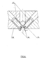
- Each beam is received and returned by a retro-reflecting strip 15 (Fig. 4,5) fixed on a support plate 16 secured to the measurement head 7, at the lower end of the arm.
- the four strip sections 15 assigned to each face of the arm 6 form a continuous polygonal contour, square in the embodiment shown (Fig. 5).
- the return beams are received and detected by the transmitting devices 13 on an appropriate receiver.
- These are devices well known in themselves and do not need to be described in more detail. They are made, for example, from light barriers of safety, LVU models built and sold by SICK FRANCE.
- the devices 13 are connected to the control and command post of the bench and are responsible, as will be seen below, for detecting any interruption of any one of the four light curtains and for controlling a predetermined process of deceleration of the movement of the arm 6 and stopping the latter, or possibly returning back to release.
- the measuring head 7 is for example a head with five topors, one vertical and four cardinals.
- This type of head is well known and can be constituted by the TP2 model built and sold by the RENISHAW Company.
- the head 7 is removably attached to the end of a tube 17 coaxial with the arm 6, suspended from the latter by means of a spring 18 and capable of sliding in a sleeve 19 on either side of which two pneumatic clamps 20 are fixed by means of split cones of the tube 17 in order to immobilize the latter relative to the sleeve 19.
- the devices 20 are supplied with compressed air by means of fittings 21 connected to an appropriate source by means of flexible conduits (not shown).
- the plate 16 carrying the retro-reflecting bands 15 as well as the support of a socket 22 making it possible to connect the sensors of the head 7 to the command and control system of the bench by means of flexible cords 23.
- the body 24 of the upper pneumatic clamping device 20 (immediately opposite the end of the arm 6) is shaped so as to receive three horizontal pins 25 arranged radially at equal angular distance from each other.
- An insulating wedge 26 is interposed between each pin 25 and its support 24.
- the pins 25 protrude radially outward and are capable of resting each in a V-shaped cradle (Fig. 6) consisting of two inclined electrical studs 27.
- the pairs of studs 27 are carried by a crown 28 secured to a recovery plate 29 fixed to the end of the arm 6.
- the two V-shaped studs 27 for receiving each pin 25 are electrically isolated from their support ring 28 and do not touch.
- the two studs 27 are connected by electrical conductors 30 to the control station of the bench. The electrical continuity between the two studs 27 is ensured by the bridging produced by the pin 25.
- the body 24 is suspended from the plate 29, that is to say from the arm 6 by means of three vertical springs 31 regularly spaced in the intervals between the pins 25 (Fig. 5). These springs 31 working at the compression, are housed in recesses 32 of the body 24 and interposed between the bottom 33 of the recesses and washers 34 retained at the end of vertical rods 35 anchored in said plate 29.
- the springs 31 are responsible for balancing the mass of the measuring head so that the pressure of the pins 25 on the V-shaped cradles 27 is substantially equal to zero.
- the crown 28 carries three electromagnets 36 arranged opposite each pin 25 relative to the axis of the arm 6.
- Each electromagnet 36 controls a push rod 3.7 movable vertically and itself controlling a flange 38 pivotally mounted about a horizontal axis 39 and the end 40 of which is in the shape of a beak is capable of bearing against the upper face of the body 24
- a spring 41 anchored, on the one hand, on the plate 29 and, on the other hand, on the flange 38 is responsible for imparting, as will be seen in detail below, the desired stiffness to the assembly 7-19 -24-28 when the electromagnet 36 is energized.
- the weight of the arm 6 and of the assembly of the measuring head and of its mounting is partially compensated or balanced by a device comprising two cables 42 anchored at one end on either side of the arm 6, at its lower part ( Fig. 1), and, at the other end, on two twin drums 43 (Fig. 7) with a horizontal axis, mounted at the top of the carriage 5 on a suitable chassis 44.
- the cables 42 at the outlet of the drums 43 are placed in the correct axis by means of a first pair of return pulleys 45, then of a second pair of return pulleys 46.
- a reduction pulley with planetary gear 47 is interposed between the two drums 43.
- the shaft 48 of the reduction pulley 47 crosses the two drums 43 and on its two ends are keyed two pulleys 49 of large diameter.
- the pulleys 49 are anchored at the ends of two cables 50, the other ends of which, after passing over an angular pulley 51, are anchored at the ends of two rods 52 (FIG. 1) of two horizontal pneumatic cylinders 53, parallel to the beams 4 and fixed to the frame 44.
- a hydraulic disc brake 54 for safety is provided in the event of a lack of air in the jacks 53, the brake 54 blocking any rotation of the shaft 48 if necessary.
- the measuring head 7 is capable of moving along any of the three reference axes, X horizontal by moving the beams 4 along the beams 3, Y horizontal by moving the carriage 5 along the beams 4 and Z vertical by movement of the slide 6 on the carriage 5, in order to carry out any measurement or control of any part previously positioned and stowed on the turntable 8.
- the optical sleeve 14 enveloping the part of the arm 6 below the carriage 5 protects the probes of the measuring head and possibly of the part to be checked in the event of the interruption of one of the scanning beams emitted by the devices 13 and returned by the bands 15 on these same devices 13.
- Such an interruption can occur for example if, during the displacement in space of the head 7, a foreign body, an obstacle or an element of the part itself penetrates into one or more of the four optical curtains constituting the protective sleeve 14. Such penetration disrupts reception at 13 of the return beam and is detected.
- the detection signal is used to stop the movement of the measuring head 7 preferably after a predetermined deceleration.
- the system computer can select the one of the four curtains concerned with a view, after stopping the head 7, to order a removal of the latter opposite the curtain disturbed optics to spread the head 7 of the intruder.
- the computer can also provide for a permanent stop of the head 7 if the withdrawal maneuver to escape said intruder has not made it possible, within a predetermined period, to remove the disturbance of said optical curtain concerned.
- optical barrier 14 is still in service even if the reflective strips 15 are no longer strictly perpendicular to the incident beams due to their retro-reflecting structure.
- Fig. 1 is shown in dashed lines in 6 ' the maximum extension towards the bottom of the slide 6. In this position, the whole of the arm 6 below the carriage 5 remains enveloped by the protective optical sleeve 14 and this of course whatever the position of the carriage 5 in the horizontal axes X and Y.
- the barrier 14 adjusts itself telescopically to the length of the slide 6 protruding below the carriage 5.
- the measuring head 7 During the toping of the measuring probes (docking of the part by the probe) the measuring head 7 must retain a certain stiffness with respect to the arm 6. This stiffness is fixed by the conditions of measurement imposed and controlled by the the computer of the bench and is provided by the three electromagnets 36 normally excited so that the spouts 40 lock the body 24 as shown in FIG. 4. Subsequently, the assembly 7-19-24 forms a block with the crown 28 and therefore the plate 29, with however a possibility of pendular movement of said assembly against the springs 41 which therefore give this assembly the desired stiffness. .. The springs 41 moreover compensate for the inertial forces during acceleration in the XY plane of the arm 6.
- the detachment of the pin 25 generates an electrical continuity solution between the two studs 27 facing each other.
- This continuity solution generates a signal used, on the one hand, to control the stopping of the head 7 and, on the other hand, to control the de-excitation of the three electromagnets 36.
- the flanges 38 are then released and release the assembly 7-19-24 which rediscovers its great sensitivity to pendulum displacement, subsequently allowing the head 7 to return to a good position away from the intruder.
- the computer determines which of the three pins 25 has peeled off and commands and controls the withdrawal movement of the head 7, on the side of the biased pin.
- the extreme sensitivity and precision of the floating assembly 7-19-24 means that the slightest accidental docking of said assembly with the part to be measured, for example, is immediately detected by the detachment of one of the pins 25, the generated signal being used by the computer to correct the trajectory according to a pre-established program.
- the elec - tro-magnets 36 are reverrouéess to continue the measurement-monitoring program always under the direction of the computer ..
- the device constituted by the two pneumatic clamps 20, the tube 17 and the spring 18 makes it possible to balance the measuring probes whatever their configuration.
- the two clamps 20 are unlocked, the tube 17 remaining in free suspension at the spring 18.
- the measuring head 7 is removed and replaced by another of a different weight which causes the lengthening or shortening of the spring 18. In this position of new balance the clamps 20 are tightened and the measuring head is ready to operate.
- the springs 31 can be adjusted in tension by means of a nut screwed onto the rod 35 and retaining the washer 34 in order to balance the weight of the assembly 7-19-24 so that the normal pressure exerted by the pins 25 on their cradle 27 is zero, the pins 25 however contacting the studs 27 to ensure electrical continuity.
- the balancing device 42 to 53 at least partially compensates for the weight of the assembly 6-7. For example, 90% of the weight is automatically and permanently counterbalanced whatever the position of the slide 6 relative to the carriage 5 and the remaining 10% are displaced by means of the motor 12, the pinion 11 and the rack 10.
- the maximum stroke of the slide 6 can be relatively large (3m for example) the reduction-reduction system 43-49-50-51 allows the cables 42 to run on the desired length for a reduced stroke (for example one meter) of the rods 52 of the jacks 53 for controlling the unwinding and winding of the cables 42 on the drums 43.
- the invention has been described in the context of application to a three-dimensional measurement bench, preferably with computerized control, but it is obvious that it could just as easily be applied to a slide movable vertically on a support itself. - even mobile along at least one horizontal axis, said slide carrying at its lower part an active head capable of carrying out a measurement, a control, a monitoring (for example by camera), a machining, a gripping function (robot) and in general, any function calling it to move in space relative to any object or objects while ensuring protection and safety, on the one hand, of said head and of its support arm and, on the other hand, of the object or objects considered.
- the invention is obviously not limited to the embodiment shown and described above, but on the contrary covers all its variants, in particular as regards the configuration of the optical barrier 14 enveloping the arm 6, the means of its realization, the elastic suspension means with controlled stiffness of the measuring head 7, the means for controlling any angular difference between the axis of the arm 6 and the axis of the tubular support 17 of the head 7 or else the means of balancing of the weight of the slide assembly 6-measuring head 7.
Landscapes
- Engineering & Computer Science (AREA)
- General Engineering & Computer Science (AREA)
- Mechanical Engineering (AREA)
- Physics & Mathematics (AREA)
- General Physics & Mathematics (AREA)
- Length Measuring Devices With Unspecified Measuring Means (AREA)
Priority Applications (1)
| Application Number | Priority Date | Filing Date | Title |
|---|---|---|---|
| EP83450003A EP0116807A1 (de) | 1983-02-21 | 1983-02-21 | Ein entlang wenigstens zwei orthogonalen Axen verschiebbarer Schlitten mit einem Kopf zum Messen, Kontrollieren, Bearbeiten, Kopieren oder ähnlichem |
Applications Claiming Priority (1)
| Application Number | Priority Date | Filing Date | Title |
|---|---|---|---|
| EP83450003A EP0116807A1 (de) | 1983-02-21 | 1983-02-21 | Ein entlang wenigstens zwei orthogonalen Axen verschiebbarer Schlitten mit einem Kopf zum Messen, Kontrollieren, Bearbeiten, Kopieren oder ähnlichem |
Publications (1)
| Publication Number | Publication Date |
|---|---|
| EP0116807A1 true EP0116807A1 (de) | 1984-08-29 |
Family
ID=8191517
Family Applications (1)
| Application Number | Title | Priority Date | Filing Date |
|---|---|---|---|
| EP83450003A Withdrawn EP0116807A1 (de) | 1983-02-21 | 1983-02-21 | Ein entlang wenigstens zwei orthogonalen Axen verschiebbarer Schlitten mit einem Kopf zum Messen, Kontrollieren, Bearbeiten, Kopieren oder ähnlichem |
Country Status (1)
| Country | Link |
|---|---|
| EP (1) | EP0116807A1 (de) |
Cited By (9)
| Publication number | Priority date | Publication date | Assignee | Title |
|---|---|---|---|---|
| DE3527063C1 (de) * | 1985-07-27 | 1986-01-30 | Fa. Carl Zeiss, 7920 Heidenheim | Verfahren und Vorrichtung zum Schutz eines beweglichen,langgestreckten Maschinenteils |
| DE3514444A1 (de) * | 1985-04-20 | 1986-10-23 | Mauser-Werke Oberndorf Gmbh, 7238 Oberndorf | Pinolenschutz von koordinaten-messmaschinen |
| DE3833680A1 (de) * | 1988-10-04 | 1990-04-05 | Zeiss Carl Fa | Schutzeinrichtung fuer langgestreckte maschinenteile |
| DE3844687A1 (de) * | 1988-10-04 | 1990-07-12 | Zeiss Carl Fa | Schutzeinrichtung fuer langgestreckte maschinenteile |
| EP0421117A1 (de) * | 1989-09-05 | 1991-04-10 | Lasag Ag | Laserstrahlbearbeitungskopf |
| FR2653368A1 (fr) * | 1989-10-25 | 1991-04-26 | Lasag Ag | Tete d'usinage a faisceau laser perfectionnee. |
| US5021632A (en) * | 1989-09-05 | 1991-06-04 | Lasag Ag | Laser beam machining head |
| EP0533051A2 (de) * | 1991-09-18 | 1993-03-24 | Firma Carl Zeiss | Schutzeinrichtung für langgestreckte Maschinenteile |
| DE10203823B4 (de) * | 2001-02-02 | 2004-09-16 | Carl Zeiss-Stiftung | Schutzvorrichtung und -verfahren für einen Tragarm |
Citations (7)
| Publication number | Priority date | Publication date | Assignee | Title |
|---|---|---|---|---|
| US3122970A (en) * | 1964-03-03 | Certificate of correction | ||
| FR2141051A5 (de) * | 1971-06-08 | 1973-01-19 | Zeiss Jena Veb Carl | |
| FR2303267A1 (fr) * | 1975-03-07 | 1976-10-01 | Stiefelmayer Kg C | Tete palpeuse |
| US4136455A (en) * | 1977-02-23 | 1979-01-30 | Century Specialties, Inc. | Floating head checking fixture |
| GB2025073A (en) * | 1978-07-07 | 1980-01-16 | Rolls Royce | Apparatus for Monitoring the State of an Electrical Circuit |
| GB2060113A (en) * | 1979-10-01 | 1981-04-29 | Schieber Universal Maschf | Guard for the zone of movement of the carriage of a flatbed knitting machine |
| EP0070108A1 (de) * | 1981-06-23 | 1983-01-19 | Rank Taylor Hobson Limited | Verbesserungen an Fühlern für Messgeräte |
-
1983
- 1983-02-21 EP EP83450003A patent/EP0116807A1/de not_active Withdrawn
Patent Citations (7)
| Publication number | Priority date | Publication date | Assignee | Title |
|---|---|---|---|---|
| US3122970A (en) * | 1964-03-03 | Certificate of correction | ||
| FR2141051A5 (de) * | 1971-06-08 | 1973-01-19 | Zeiss Jena Veb Carl | |
| FR2303267A1 (fr) * | 1975-03-07 | 1976-10-01 | Stiefelmayer Kg C | Tete palpeuse |
| US4136455A (en) * | 1977-02-23 | 1979-01-30 | Century Specialties, Inc. | Floating head checking fixture |
| GB2025073A (en) * | 1978-07-07 | 1980-01-16 | Rolls Royce | Apparatus for Monitoring the State of an Electrical Circuit |
| GB2060113A (en) * | 1979-10-01 | 1981-04-29 | Schieber Universal Maschf | Guard for the zone of movement of the carriage of a flatbed knitting machine |
| EP0070108A1 (de) * | 1981-06-23 | 1983-01-19 | Rank Taylor Hobson Limited | Verbesserungen an Fühlern für Messgeräte |
Cited By (15)
| Publication number | Priority date | Publication date | Assignee | Title |
|---|---|---|---|---|
| DE3514444A1 (de) * | 1985-04-20 | 1986-10-23 | Mauser-Werke Oberndorf Gmbh, 7238 Oberndorf | Pinolenschutz von koordinaten-messmaschinen |
| DE3527063C1 (de) * | 1985-07-27 | 1986-01-30 | Fa. Carl Zeiss, 7920 Heidenheim | Verfahren und Vorrichtung zum Schutz eines beweglichen,langgestreckten Maschinenteils |
| FR2585279A1 (fr) * | 1985-07-27 | 1987-01-30 | Zeiss Carl Fa | Procede et dispositif de protection d'une partie allongee et mobile d'une machine |
| US5111591A (en) * | 1988-10-04 | 1992-05-12 | Carl-Zeiss-Stiftung | Protective arrangement for a longitudinally extendible machine component |
| DE3844687A1 (de) * | 1988-10-04 | 1990-07-12 | Zeiss Carl Fa | Schutzeinrichtung fuer langgestreckte maschinenteile |
| US5038488A (en) * | 1988-10-04 | 1991-08-13 | Carl-Zeiss-Stiftung | Protective arrangement for a longitudinally extendible machine component |
| DE3833680A1 (de) * | 1988-10-04 | 1990-04-05 | Zeiss Carl Fa | Schutzeinrichtung fuer langgestreckte maschinenteile |
| EP0421117A1 (de) * | 1989-09-05 | 1991-04-10 | Lasag Ag | Laserstrahlbearbeitungskopf |
| US5021632A (en) * | 1989-09-05 | 1991-06-04 | Lasag Ag | Laser beam machining head |
| FR2653368A1 (fr) * | 1989-10-25 | 1991-04-26 | Lasag Ag | Tete d'usinage a faisceau laser perfectionnee. |
| EP0533051A2 (de) * | 1991-09-18 | 1993-03-24 | Firma Carl Zeiss | Schutzeinrichtung für langgestreckte Maschinenteile |
| EP0533051A3 (en) * | 1991-09-18 | 1993-04-14 | Firma Carl Zeiss | Protection device for elongated machine parts |
| US5269068A (en) * | 1991-09-18 | 1993-12-14 | Carl-Zeiss-Stiftung | Protective device for a longitudinally extending machine component |
| DE10203823B4 (de) * | 2001-02-02 | 2004-09-16 | Carl Zeiss-Stiftung | Schutzvorrichtung und -verfahren für einen Tragarm |
| DE10203823B8 (de) * | 2001-02-02 | 2005-01-13 | Carl Zeiss-Stiftung | Schutzvorrichtung und -verfahren für einen Tragarm |
Similar Documents
| Publication | Publication Date | Title |
|---|---|---|
| EP0116807A1 (de) | Ein entlang wenigstens zwei orthogonalen Axen verschiebbarer Schlitten mit einem Kopf zum Messen, Kontrollieren, Bearbeiten, Kopieren oder ähnlichem | |
| EP1777494A1 (de) | System zur Bestimmung der Lage einer 3D Koordinatenmessmaschine oder einer Bearbeitungsmaschine in einem ortsfesten Bezugssystem | |
| WO2005077585A1 (fr) | Outil de serrage, en particulier pince a souder, avec un systeme de compensation | |
| FR2587784A1 (fr) | Structure extensible et retractable a plan orientable | |
| EP3536899B1 (de) | Bohrmaschine, die eine anschlussvorrichtung für eine messvorrichtung der vertikalität umfasst | |
| CA1167245A (fr) | Dispositif suiveur de pas de rainures helicoidales | |
| EP0301989B1 (de) | Maschine zum Abwickeln von Bahnen mit Gestellen für Wickelrollen | |
| EP0309845A1 (de) | Anlage zur Zielverfolgung | |
| EP0141717B1 (de) | Positioniereinrichtung für Roboter | |
| CA2813835A1 (fr) | Dispositif de test electromagnetique d'un objet | |
| WO1994017952A1 (fr) | Machine automatique de soudage 'in situ' suivant un profil a tronçon curviligne, et avec commande programmable d'extrapolation | |
| FR2678354A1 (fr) | Dispositif de montage reglable d'un spot. | |
| EP3962844A1 (de) | Vorrichtung zum blockieren eines fahrzeugs vor einer ladebrücke | |
| EP3338944A1 (de) | Werkzeugmaschine, die eine montagekonfiguration mit auskragendem werkzeug umfasst | |
| EP0115735B1 (de) | Vorrichtung zur Feststellung von Rissen in kontinuierlich gewalzten Stahlbrammen | |
| EP0044245A1 (de) | Greiforgan mit optischen Sensoren und Vorrichtung mit Anwendung dieses Organs | |
| FR2573724A1 (fr) | Procede et dispositif opto-electronique permettant a une structure mobile de suivre les deplacements d'une autre structure. | |
| EP0143134A1 (de) | Gewichtsausgleichsvorrichtung für Roboterarm | |
| EP0619470A1 (de) | Vorrichtung zur horizontalen Projektion eines Laserstrahles | |
| EP2755795B1 (de) | Vorrichtung zur montage eines motors und verfahren zur montage und überwachung einer solchen motorvorrichtung | |
| EP0165117A1 (de) | Verfahren zum Verfolgen einer Naht durch einen Schweisskopf und Einrichtung zur Durchführung dieses Verfahrens | |
| EP3931064B1 (de) | System zur immobilisierung eines medizinischen roboters | |
| FR2573723A1 (fr) | Procede et dispositif permettant a une structure mobile de suivre les deplacements d'une autre structure. | |
| FR2491048A1 (fr) | Installation de levage d'une charge de grande dimension a l'aide de plusieurs dispositifs de levage independants agissant en plusieurs points de charge, notamment destinee au levage d'un avion en vue de sa reparation | |
| CA1135488A (fr) | Procede de positionnement precis d'un ou de plusieurs outils sur le plan de coupe d'une structure tubulaire ainsi que dispositif de mise en oeuvre du procede |
Legal Events
| Date | Code | Title | Description |
|---|---|---|---|
| PUAI | Public reference made under article 153(3) epc to a published international application that has entered the european phase |
Free format text: ORIGINAL CODE: 0009012 |
|
| AK | Designated contracting states |
Designated state(s): BE CH DE FR GB IT LI NL SE |
|
| STAA | Information on the status of an ep patent application or granted ep patent |
Free format text: STATUS: THE APPLICATION IS DEEMED TO BE WITHDRAWN |
|
| 18D | Application deemed to be withdrawn |
Effective date: 19850512 |
|
| RIN1 | Information on inventor provided before grant (corrected) |
Inventor name: CHEVRIER, RENE |