EP0116325B1 - Appareil destiné au dosage des liquides dans les dispositifs d'infusion ou de transfusion - Google Patents
Appareil destiné au dosage des liquides dans les dispositifs d'infusion ou de transfusion Download PDFInfo
- Publication number
- EP0116325B1 EP0116325B1 EP84100863A EP84100863A EP0116325B1 EP 0116325 B1 EP0116325 B1 EP 0116325B1 EP 84100863 A EP84100863 A EP 84100863A EP 84100863 A EP84100863 A EP 84100863A EP 0116325 B1 EP0116325 B1 EP 0116325B1
- Authority
- EP
- European Patent Office
- Prior art keywords
- housing
- metering device
- hose member
- pressing element
- hose
- Prior art date
- Legal status (The legal status is an assumption and is not a legal conclusion. Google has not performed a legal analysis and makes no representation as to the accuracy of the status listed.)
- Expired
Links
Images


Classifications
-
- A—HUMAN NECESSITIES
- A61—MEDICAL OR VETERINARY SCIENCE; HYGIENE
- A61M—DEVICES FOR INTRODUCING MEDIA INTO, OR ONTO, THE BODY; DEVICES FOR TRANSDUCING BODY MEDIA OR FOR TAKING MEDIA FROM THE BODY; DEVICES FOR PRODUCING OR ENDING SLEEP OR STUPOR
- A61M39/00—Tubes, tube connectors, tube couplings, valves, access sites or the like, specially adapted for medical use
- A61M39/22—Valves or arrangement of valves
- A61M39/28—Clamping means for squeezing flexible tubes, e.g. roller clamps
- A61M39/285—Cam clamps, e.g. roller clamps with eccentric axis
Definitions
- the invention relates to a dosing device for liquids for infusion or transfusion devices with a flexible liquid line passing through a housing, which contains a tube piece made of highly elastic elastomeric material inside the housing, and with a pressing element supported on the housing for compressing the tube piece.
- a container containing the infusion or transfusion liquid with a downward-pointing opening and a connected liquid line is usually suspended so high that the liquid pressure in the line is higher than the venous pressure of the patient.
- the liquid is first fed to an intermediate container in the liquid line and from there to the patient. Due to the different boundary conditions, e.g. the venous pressure of the patient, the viscosity of the liquid, and the different filling level of the liquid container as well as due to therapeutically necessary specific doses of the liquid, it is necessary to precisely regulate the flow rate of the liquid.
- a liquid line has a line section made of elastic material which can be pressed together with a pressing element supported on a housing.
- the elastic hose element is guided through an opening in the housing that is larger than the cross section of the hose section.
- the inner opening of the tube piece is not a circular cross section, but has a plurality of radially uniformly distributed and axially extending V-shaped grooves.
- Such a piece of hose cannot consequently completely prevent the flow even in the fully compressed state.
- a displacement within the housing of the pressing element is possible, since the piece of hose cannot be locked on the housing.
- Dosing devices of the type mentioned at the outset are known with a liquid line passing through a housing and a clamping element which consists of a roller which is guided in the housing and presses on the hose cross section (DE-A-2 637 495).
- the metering amount which is usually determined as the number of drops of liquid falling into the intermediate container per unit of time, cannot be kept constant over a long period of time with such devices, since the PVC hoses that are usually used can deform due to their tendency to creep (cold fluidity) .
- a metering device with a housing and a substantially cylindrical valve chamber provided in the housing, two connection ports, each projecting from the housing and the valve chamber in radially opposite directions, and a plug which can be rotated with a handle and which Valve chamber is used sealingly.
- a passage is provided in the lateral surface of the plug which, depending on the rotational position of the plug, releases flow cross-sections of different sizes between the connecting pieces (DE-A-2 735 955).
- the invention has for its object to provide a metering device of the type mentioned that allows an exact, time-constant and reproducible adjustable dosage of liquids even with a piece of tubing with a circular inner cross section and injection of injection liquids.
- the tube piece has a thickening over part of its length, that the housing is secured against longitudinal displacement on the thickening of the tube piece, and that the pressing element acts on the tube piece outside the region of the thickening.
- the liquid line can be made in the previous manner from a suitable plastic. At a suitable point, it contains an elastomeric piece of tubing which is surrounded by a housing and which, together with this housing, a pressing element and an adjusting device, forms the metering device.
- the hose section has a high elasticity and restoring force, so that the cross-sectional area of the hose section always strives to achieve its relaxed original state, provided that the regulating element of the metering device, here a pressing element, allows it.
- a change in the position of the pressure element causes an immediate change in the flow cross-section of the hose section, even if the pressure element has been reset.
- the dosing device according to the invention guarantees - in the case of intravenous infusion and transfusion devices an essential safety aspect - a high degree of tightness against air entry because the flow-regulating device, here the piece of tubing, consists of one piece.
- the dosing device can be manufactured inexpensively.
- the housing is produced in one piece as an injection molded part. The housing and the actuating device as well as the pushing element do not need to be sterilized because only the tube piece comes into contact with the infusion or transfusion liquid, which reduces the costs the sterilization of the dosing device and the risks of poor sterilization.
- the tube piece can also be used to inject additional medication or liquids with a syringe.
- the tube piece consists of a highly elastic, elastomeric material ensures that the metering device remains sealed even after the needle cannula has been inserted and withdrawn.
- the thickening of the tube piece allows greater freedom in the cavity of the tube piece with regard to the insertion depth of the needle cannula and thus increases the safety of the device.
- the piece of tubing is therefore of double use in that, on the one hand, it offers the possibility of injecting medication or liquids and, on the other hand, by metering the flow rate of the infusion or transfusion liquid in conjunction with the pressure element. Otherwise two hose sections are required for these tasks.
- a preferred embodiment of the invention is characterized in that the pressing element is guided transversely to the longitudinal direction of the tube piece and that the front side of the pressing element pressing against the tube piece is inclined to the direction of movement of the pressing element.
- Such an asymmetrical deformation of the hose section has the advantage of successively clamping the hose section from one side, thereby preventing the hose section from having a different cross-sectional shape, e.g. B. in the form of an eight, despite the elasticity maintains its deformation or changes its cross-sectional shape by leaps and bounds. This ensures a particularly exact, reproducible adjustable dosage.
- An advantageous development of the invention is characterized in that the housing has a puncture channel for a needle cannula leading to the tube piece. In this way, the needle cannula is fed to a specific point on the tube piece.
- a preferred embodiment of the invention is characterized in that the puncture channel runs at an acute angle to the longitudinal axis of the tube piece. This has the advantage that the most favorable insertion angle is maintained due to the guidance of the needle cannula. This increases the safety when injecting, since a maximum free path for the needle tip in the tube piece is achieved. This is important when the need to inject particularly quickly in emergencies, since the needle tip is positioned more easily and safely in the cross-section of the tube, and the further tube wall cannot be perforated if the needle is inserted too deeply, as a result of which the injection fluid would not get into the bloodstream.
- the pressing element can be moved via a manually adjustable self-locking adjusting device.
- the adjusting device can preferably consist of a threaded spindle mounted in the housing. With a threaded spindle, depending on the thread pitch, a particularly precise and reproducible dosage is possible.
- the adjusting device can also have a removable handle part. This significantly increases the security against unauthorized adjustment of the metering device, since it cannot be adjusted when the handle part is removed.
- the exemplary embodiments of a metering device 1 shown in FIGS. 1 to 9 are arranged in an infusion or transfusion device.
- the dosing device 1 in the liquid line 2 is consequently between an infusion container and a patient. It has a housing 3 for receiving an adjusting device 4, a pressing element 5 and a piece of hose 6 inserted into the liquid line 2.
- the hose piece 6 is a commercially available injection part made of a highly elastic elastomer, which is usually interposed in a PVC liquid line 2 in order to offer the possibility, e.g. Inject medication during an infusion or transfusion.
- the elastic hose piece 6 overlaps the ends of the liquid line 2 with its two ends 63, 64 in an airtight manner.
- the tube piece 6 has in its central part a thickening 65 which is reduced at its two ends in the form of an annular shoulder 61, 62 to a cylindrical tube section 63, 64 which is somewhat larger than the cross section of the liquid line 2.
- This thickening 65 fixes the position of the entire metering device 1 at a certain one Place in the liquid line 2. It also allows the wall thickness to be increased. This is important if the hose section 6 in the metering device 1 is also to be used for injection.
- the thickening 65 creates the longest possible path in the cavity 60 of the tube piece 6 for the insertion of a needle cannula (not shown).
- the highly elastic material of the tube piece 6 ensures that the puncture hole closes again immediately after piercing the wall 'of the tube piece 6 with a needle cannula and after pulling out this needle cannula.
- the housing 3 forms a chamber 7 in which the tube piece 6 is inserted.
- the chamber 7 is essentially adapted to the outer contour of the tube piece 6 and has a nozzle 71 in the area of the thin cylindrical tube section 63 and a channel 72 in the area of the thin cylindrical tube section 64.
- the annular shoulders 61, 62 of the hose section 6 each adjoin a wall of the chamber 7, so that the position of the hose section 6 is thereby determined.
- a puncture channel 8 for guiding a needle cannula to the chamber 7 runs through the housing 3 at an acute angle relative to the longitudinal axis of the housing. This puncture channel 8 opens directly in front of the annular shoulder 61 of the hose section 6, which is formed by the step-shaped thickening 65 of the hose section 6 .
- the exemplary embodiments of the metering device 1 of FIGS. 1 to 8 use as a pressing element a cuboid-shaped metering wedge 5, which presses on its wide sides in a straight guide path 32 running at right angles to the hose piece onto the cylindrical hose section 64 shortly before the annular shoulder 61 of the hose piece 6.
- the end face 51 of the dosing wedge 5 presses the hose section 64 in the direction of the flat bottom surface of the channel 72. It extends obliquely to this bottom surface in the cross-sectional plane of the hose section 6. In this way, the hose section 64 is increasingly clamped from one side when the metering wedge 5 is delivered.
- the dosing wedge 5 is actuated by an adjusting device 4, the resetting being carried out on the basis of the elastic restoring force of the tube piece 6.
- the setting device 5 can, for example, as shown in FIGS. 1 to 4, be a threaded spindle 40, which is located in a thread 33 of the housing 30 and is actuated by a setting wheel 41.
- the adjusting wheel 41 engages e.g. with a hexagon 42 in a corresponding recess 43 in the interior of the threaded spindle 40. This positive connection is releasable and therefore enables the setting wheel 41 to be removed, e.g.
- a hollow cylinder 44 projecting coaxially from the adjusting wheel 41 with the hexagon 42 and fitting into a corresponding hollow cylindrical recess 34 in the housing part 3a serves to guide the adjusting wheel 41 and prevents the hexagon 42 from breaking off due to tilting.
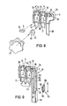
- the adjusting device 4 consists of an eccentric 45 which is fastened on an eccentric shaft 46.
- the eccentric shaft 46 is held on the one hand by the bearing 35 in the housing 3a, and on the other hand is received by a key part 48 of the adjusting wheel 47, which in turn is mounted in the housing 36 with the key part 48.
- the eccentric shaft 46 is positively and releasably connected to the adjusting wheel 47 and in its part 49 encompassed by the key part 48 of the adjusting wheel 47, for. B. formed as a square or hexagon.
- this adjusting device is also designed to be self-locking, so that the adjusting wheel 41 cannot be adjusted by itself.
- the remaining parts of this metering device 1 correspond to the previous embodiment.
- This lever 90 is articulated on the housing 3a at an articulation point 97 on one side with its long leg 92 such that the long one Leg 92 assumes a position inclined to the housing wall 36 in the relaxed undeformed state of the hose section 6.
- the slide 93 is inserted, which is supported with its part located in the housing 3 on the housing wall 36 and thereby presses on the long leg 92 of the lever 90.
- the slide 93 If the slide 93 is moved away from the articulation point 97 of the lever 90, it presses increasingly on the long leg 92 like a wedge due to the inclination of the lever 90, so that the short leg 91 of the lever 90, which is angled at almost a right angle, increasingly presses on the tube piece 6 .
- the end face 98 of the short leg 91 of the lever 90 acting on the hose section 6 is beveled transversely to the hose direction in accordance with the metering wedge 5, so that the hose section 6 is increasingly clamped from one side when the lever 90 is pivoted into the closed position.
- the slide 93 is guided in a slot 37 in the upper housing wall 36.
- the inside 39 of the housing wall 36 is ribbed so that a self-locking of the adjusting device is achieved in connection with the ribbed surface 95 of the part 94 of the slide 93 located in the housing 3.
- the obree part 96 of the slide 93 can also be removable in accordance with the setting wheels 41, 47 of the previous exemplary embodiments, in order to prevent unauthorized actuation of the metering device 1 by unauthorized persons.
- the housing 3 is an injection molded part in one piece, for. B. made of polypropylene. All of the housings shown are designed in such a way that they have two housing parts 3a, 3b which can be pivoted in the longitudinal direction, for example about a film hinge 39 (FIGS. 4, 8, 9).
- the two housing parts 3a, 3b can be combined press together with the help of snap connections 31 a, 31 b. After the two housing parts 3a, 3b have been pressed together, the connection can no longer be released without destruction.
- the two housing parts have a handle 38 running parallel to the liquid line 2, which enables one-hand operation of the adjusting device 4 in combination with an adjusting wheel 41, 47 or a slide 93.
- the outer wheels of the adjusting wheels 41, 47 and the slide 93 are shaped in such a way that they can easily be operated with the thumb, while the other fingers of the hand encompass the grip piece 38 on the housing 3.
Landscapes
- Health & Medical Sciences (AREA)
- Heart & Thoracic Surgery (AREA)
- Pulmonology (AREA)
- Engineering & Computer Science (AREA)
- Anesthesiology (AREA)
- Biomedical Technology (AREA)
- Hematology (AREA)
- Life Sciences & Earth Sciences (AREA)
- Animal Behavior & Ethology (AREA)
- General Health & Medical Sciences (AREA)
- Public Health (AREA)
- Veterinary Medicine (AREA)
- Infusion, Injection, And Reservoir Apparatuses (AREA)
Claims (10)
Priority Applications (1)
| Application Number | Priority Date | Filing Date | Title |
|---|---|---|---|
| AT84100863T ATE24112T1 (de) | 1983-02-11 | 1984-01-27 | Dosiervorrichtung fuer fluessigkeiten fuer infusions- oder transfusionsgeraete. |
Applications Claiming Priority (2)
| Application Number | Priority Date | Filing Date | Title |
|---|---|---|---|
| DE3304831 | 1983-02-11 | ||
| DE19833304831 DE3304831A1 (de) | 1983-02-11 | 1983-02-11 | Dosiervorrichtung fuer fluessigkeiten fuer infusions- oder transfusionsgeraete |
Publications (2)
| Publication Number | Publication Date |
|---|---|
| EP0116325A1 EP0116325A1 (fr) | 1984-08-22 |
| EP0116325B1 true EP0116325B1 (fr) | 1986-12-10 |
Family
ID=6190659
Family Applications (1)
| Application Number | Title | Priority Date | Filing Date |
|---|---|---|---|
| EP84100863A Expired EP0116325B1 (fr) | 1983-02-11 | 1984-01-27 | Appareil destiné au dosage des liquides dans les dispositifs d'infusion ou de transfusion |
Country Status (4)
| Country | Link |
|---|---|
| US (1) | US4576593A (fr) |
| EP (1) | EP0116325B1 (fr) |
| AT (1) | ATE24112T1 (fr) |
| DE (2) | DE3304831A1 (fr) |
Families Citing this family (14)
| Publication number | Priority date | Publication date | Assignee | Title |
|---|---|---|---|---|
| GB2187535B (en) * | 1986-03-05 | 1989-11-15 | Heatrae Sadia Heating Ltd | Fluid flow control valve |
| JPH01198539A (ja) * | 1987-10-26 | 1989-08-10 | Marui Ika:Kk | 脳外科用ウオータージェットメス装置 |
| US4969486A (en) * | 1989-03-24 | 1990-11-13 | Puzio Eugene T | Flow control apparatus |
| JP2868246B2 (ja) * | 1989-10-19 | 1999-03-10 | 旭光学工業株式会社 | カメラのファインダー |
| US5197708A (en) * | 1992-08-11 | 1993-03-30 | Flow-Rite Controls, Ltd. | Tubing pinch valve device |
| US5419772A (en) * | 1993-09-29 | 1995-05-30 | Teitz; Bernard R. | Surgical irrigation apparatus for cleaning and sterilizing wounds and surgical areas during surgery |
| US20070293742A1 (en) * | 1998-11-30 | 2007-12-20 | Novo Nordisk A/S | Medical System And A Method Of Controlling The System For Use By A Patient For Medical Self Treatment |
| US7569028B2 (en) * | 2001-10-12 | 2009-08-04 | Flexcorp | Fluid flow adjustment mechanism |
| US6929235B1 (en) * | 2002-04-19 | 2005-08-16 | Massachusetts Institute Of Technology | Apparatus for flow rate control |
| US7121521B2 (en) * | 2003-04-08 | 2006-10-17 | Fiskars Brands, Inc. | Spigot |
| US20050107757A1 (en) * | 2003-11-14 | 2005-05-19 | Ipas | Medical vacuum aspiration device |
| WO2014144381A1 (fr) | 2013-03-15 | 2014-09-18 | Diversey, Inc. | Bouchon doseur réglable |
| USD746137S1 (en) | 2013-11-15 | 2015-12-29 | Diversey, Inc. | Dosing cap |
| US20150216622A1 (en) * | 2014-02-05 | 2015-08-06 | Albert Vartanian | Ergonomically optimized, in-line water valve assembly for use with a dental handpiece |
Family Cites Families (12)
| Publication number | Priority date | Publication date | Assignee | Title |
|---|---|---|---|---|
| FR1306090A (fr) * | 1961-08-30 | 1962-10-13 | Robinet | |
| US3329391A (en) * | 1964-09-28 | 1967-07-04 | William V Deane | Surgical pinch valve |
| US3460526A (en) * | 1965-08-23 | 1969-08-12 | Horizon Ind Ltd | Apparatus for flow-control and pressure measurement |
| US3497175A (en) * | 1967-09-11 | 1970-02-24 | Betty K Koland | Fluid regulator and closure valve |
| US3759483A (en) * | 1971-05-14 | 1973-09-18 | T Baxter | Fluid actuated control valve |
| US3848634A (en) * | 1972-08-16 | 1974-11-19 | United States Surgical Corp | Fluid control system for controlling intravenous flow rate |
| US3831600A (en) * | 1973-04-02 | 1974-08-27 | Alza Corp | Fluid flow control |
| US3948477A (en) * | 1973-07-02 | 1976-04-06 | United States Surgical Corporation | Screw clamp for flexible tubing |
| US3861388A (en) * | 1973-07-30 | 1975-01-21 | Robert Lee Vaughn | Apparatus for administering supplemental medication with parenteral solutions |
| US3960149A (en) * | 1974-11-13 | 1976-06-01 | Abbott Laboratories | Flow control device |
| SE8000525L (sv) * | 1979-02-01 | 1980-08-02 | Ronald L Voller | Rorklemma |
| US4410164A (en) * | 1981-12-31 | 1983-10-18 | Baxter Travenol Laboratories, Inc. | Modular flow control system |
-
1983
- 1983-02-11 DE DE19833304831 patent/DE3304831A1/de not_active Withdrawn
-
1984
- 1984-01-27 EP EP84100863A patent/EP0116325B1/fr not_active Expired
- 1984-01-27 DE DE8484100863T patent/DE3461594D1/de not_active Expired
- 1984-01-27 AT AT84100863T patent/ATE24112T1/de not_active IP Right Cessation
- 1984-02-08 US US06/577,967 patent/US4576593A/en not_active Expired - Fee Related
Also Published As
| Publication number | Publication date |
|---|---|
| US4576593A (en) | 1986-03-18 |
| DE3304831A1 (de) | 1984-08-16 |
| DE3461594D1 (en) | 1987-01-22 |
| EP0116325A1 (fr) | 1984-08-22 |
| ATE24112T1 (de) | 1986-12-15 |
Similar Documents
| Publication | Publication Date | Title |
|---|---|---|
| EP0116325B1 (fr) | Appareil destiné au dosage des liquides dans les dispositifs d'infusion ou de transfusion | |
| DE60029556T2 (de) | System zur Verabreichung von Arzneimittlen mit einem Arzneimittelbehälter und dessen Halterung | |
| DE2945405C2 (fr) | ||
| DE102004042581B4 (de) | Auto-Pen für Zweikammerampulle | |
| EP0581788B1 (fr) | Dispositif d'injection | |
| DE3146541C2 (fr) | ||
| WO1998001172A1 (fr) | Appareil pour l'injection de liquide | |
| CH661445A5 (de) | Nadelloser hypodermatischer injektor. | |
| DE2637908C3 (de) | Nadelhalter fur eine medizinische Verabreichungsvorrichtung mit einer Filteranordnung | |
| DE1566649A1 (de) | Automatische Infusionsvorrichtung | |
| EP0652027A1 (fr) | Dispositif d'injection | |
| DE2654655A1 (de) | Infusionsvorrichtung | |
| WO2010140063A2 (fr) | Dispositif d'administration de médicaments fluides | |
| WO1993023099A1 (fr) | Dispositif d'injection a usage unique | |
| EP0370997A2 (fr) | Embout pour un dispositif de perfusion ou similaire | |
| EP2934753B1 (fr) | Pipette pour dosage | |
| DE2735955C2 (de) | Dosiervorrichtung für Übertragungsgeräte der Infusions- oder Transfusionstechnik | |
| EP0249617A1 (fr) | Pince de serrage pour tubes souples a infusion. | |
| WO2017013124A1 (fr) | Dispositif d'actionnement pour l'administration d'un bolus | |
| WO2008135475A1 (fr) | Pièce tubulaire moulée pour appareils de perfusion | |
| DE1966623A1 (de) | Zur einmaligen benutzung bestimmte vorrichtung fuer die aufnahme und ausgabe einer dosis von verunreinigungsempfindlichen behandlungsfluessigkeiten | |
| EP3104928B1 (fr) | Dispositif de raccordement stérile d'articles médicaux à usage unique | |
| DE19930791B4 (de) | Arretierbarer Nadeladapter | |
| EP0271785B1 (fr) | Dispositif de dosage du débit d'un écoulement de liquide dans le corps d'un être vivant | |
| DE10233925A1 (de) | Spritzvorrichtung zur Injektion mindestens zweier flüssiger Therapeutika |
Legal Events
| Date | Code | Title | Description |
|---|---|---|---|
| PUAI | Public reference made under article 153(3) epc to a published international application that has entered the european phase |
Free format text: ORIGINAL CODE: 0009012 |
|
| AK | Designated contracting states |
Designated state(s): AT BE CH DE FR GB IT LI LU NL SE |
|
| 17P | Request for examination filed |
Effective date: 19841215 |
|
| GRAA | (expected) grant |
Free format text: ORIGINAL CODE: 0009210 |
|
| AK | Designated contracting states |
Kind code of ref document: B1 Designated state(s): AT BE CH DE FR GB IT LI LU NL SE |
|
| PG25 | Lapsed in a contracting state [announced via postgrant information from national office to epo] |
Ref country code: NL Effective date: 19861210 Ref country code: IT Free format text: LAPSE BECAUSE OF FAILURE TO SUBMIT A TRANSLATION OF THE DESCRIPTION OR TO PAY THE FEE WITHIN THE PRESCRIBED TIME-LIMIT;WARNING: LAPSES OF ITALIAN PATENTS WITH EFFECTIVE DATE BEFORE 2007 MAY HAVE OCCURRED AT ANY TIME BEFORE 2007. THE CORRECT EFFECTIVE DATE MAY BE DIFFERENT FROM THE ONE RECORDED. Effective date: 19861210 Ref country code: BE Effective date: 19861210 |
|
| REF | Corresponds to: |
Ref document number: 24112 Country of ref document: AT Date of ref document: 19861215 Kind code of ref document: T |
|
| PG25 | Lapsed in a contracting state [announced via postgrant information from national office to epo] |
Ref country code: SE Effective date: 19861231 |
|
| REF | Corresponds to: |
Ref document number: 3461594 Country of ref document: DE Date of ref document: 19870122 |
|
| PG25 | Lapsed in a contracting state [announced via postgrant information from national office to epo] |
Ref country code: AT Effective date: 19870127 |
|
| PG25 | Lapsed in a contracting state [announced via postgrant information from national office to epo] |
Ref country code: LU Free format text: LAPSE BECAUSE OF NON-PAYMENT OF DUE FEES Effective date: 19870131 Ref country code: LI Effective date: 19870131 Ref country code: CH Effective date: 19870131 |
|
| ET | Fr: translation filed | ||
| NLV1 | Nl: lapsed or annulled due to failure to fulfill the requirements of art. 29p and 29m of the patents act | ||
| REG | Reference to a national code |
Ref country code: CH Ref legal event code: PL |
|
| PLBE | No opposition filed within time limit |
Free format text: ORIGINAL CODE: 0009261 |
|
| STAA | Information on the status of an ep patent application or granted ep patent |
Free format text: STATUS: NO OPPOSITION FILED WITHIN TIME LIMIT |
|
| 26N | No opposition filed | ||
| PGFP | Annual fee paid to national office [announced via postgrant information from national office to epo] |
Ref country code: GB Payment date: 19910205 Year of fee payment: 8 |
|
| PGFP | Annual fee paid to national office [announced via postgrant information from national office to epo] |
Ref country code: FR Payment date: 19910208 Year of fee payment: 8 |
|
| PGFP | Annual fee paid to national office [announced via postgrant information from national office to epo] |
Ref country code: DE Payment date: 19910226 Year of fee payment: 8 |
|
| PG25 | Lapsed in a contracting state [announced via postgrant information from national office to epo] |
Ref country code: GB Effective date: 19920127 |
|
| GBPC | Gb: european patent ceased through non-payment of renewal fee | ||
| PG25 | Lapsed in a contracting state [announced via postgrant information from national office to epo] |
Ref country code: FR Effective date: 19920930 |
|
| PG25 | Lapsed in a contracting state [announced via postgrant information from national office to epo] |
Ref country code: DE Effective date: 19921001 |
|
| REG | Reference to a national code |
Ref country code: FR Ref legal event code: ST |