EP0115721A1 - Procédé et dispositif de tomographie - Google Patents
Procédé et dispositif de tomographie Download PDFInfo
- Publication number
- EP0115721A1 EP0115721A1 EP83402423A EP83402423A EP0115721A1 EP 0115721 A1 EP0115721 A1 EP 0115721A1 EP 83402423 A EP83402423 A EP 83402423A EP 83402423 A EP83402423 A EP 83402423A EP 0115721 A1 EP0115721 A1 EP 0115721A1
- Authority
- EP
- European Patent Office
- Prior art keywords
- axis
- plane
- sensitive surface
- source
- radiation
- Prior art date
- Legal status (The legal status is an assumption and is not a legal conclusion. Google has not performed a legal analysis and makes no representation as to the accuracy of the status listed.)
- Withdrawn
Links
- 238000003325 tomography Methods 0.000 title claims abstract description 16
- 238000000034 method Methods 0.000 title claims description 11
- 230000005855 radiation Effects 0.000 claims abstract description 37
- 238000006073 displacement reaction Methods 0.000 claims description 14
- 230000001360 synchronised effect Effects 0.000 claims description 7
- 230000001131 transforming effect Effects 0.000 claims description 7
- 230000001678 irradiating effect Effects 0.000 claims description 4
- 238000007689 inspection Methods 0.000 abstract 1
- 230000009466 transformation Effects 0.000 abstract 1
- 238000010521 absorption reaction Methods 0.000 description 3
- 238000012550 audit Methods 0.000 description 2
- 238000010586 diagram Methods 0.000 description 2
- XQPRBTXUXXVTKB-UHFFFAOYSA-M caesium iodide Chemical compound [I-].[Cs+] XQPRBTXUXXVTKB-UHFFFAOYSA-M 0.000 description 1
- 230000001419 dependent effect Effects 0.000 description 1
- 238000001514 detection method Methods 0.000 description 1
- 238000009792 diffusion process Methods 0.000 description 1
- 238000009659 non-destructive testing Methods 0.000 description 1
- 230000000149 penetrating effect Effects 0.000 description 1
Images
Classifications
-
- G—PHYSICS
- G01—MEASURING; TESTING
- G01N—INVESTIGATING OR ANALYSING MATERIALS BY DETERMINING THEIR CHEMICAL OR PHYSICAL PROPERTIES
- G01N23/00—Investigating or analysing materials by the use of wave or particle radiation, e.g. X-rays or neutrons, not covered by groups G01N3/00 – G01N17/00, G01N21/00 or G01N22/00
- G01N23/02—Investigating or analysing materials by the use of wave or particle radiation, e.g. X-rays or neutrons, not covered by groups G01N3/00 – G01N17/00, G01N21/00 or G01N22/00 by transmitting the radiation through the material
- G01N23/04—Investigating or analysing materials by the use of wave or particle radiation, e.g. X-rays or neutrons, not covered by groups G01N3/00 – G01N17/00, G01N21/00 or G01N22/00 by transmitting the radiation through the material and forming images of the material
- G01N23/046—Investigating or analysing materials by the use of wave or particle radiation, e.g. X-rays or neutrons, not covered by groups G01N3/00 – G01N17/00, G01N21/00 or G01N22/00 by transmitting the radiation through the material and forming images of the material using tomography, e.g. computed tomography [CT]
-
- G—PHYSICS
- G01—MEASURING; TESTING
- G01N—INVESTIGATING OR ANALYSING MATERIALS BY DETERMINING THEIR CHEMICAL OR PHYSICAL PROPERTIES
- G01N2223/00—Investigating materials by wave or particle radiation
- G01N2223/40—Imaging
- G01N2223/419—Imaging computed tomograph
Definitions
- the present invention relates to a tomography method and device. It applies in particular to the non-destructive testing of parts in the Industry.
- the subject of the present invention is a method and a tomography device which do not have this drawback, in particular in that they are much simpler and much less expensive than the known methods and devices mentioned above.
- the present invention relates to a method of tomography of an object along a section thereof contained in a plane, characterized in that it consists in irradiating the object by means of a fixed source of radiation while animating this object and a surface sensitive to said radiation, placed after the object with respect to the source and also contained in a plane, with synchronous rotational movements and in the same direction, respectively around a first axis and d 'a second parallel axis, arranged so that the first axis is transformed into the second axis by a homothety of positive ratio and of center the source, the object and the sensitive surface being arranged so that they remain exposed to said radiation when '' they perform their rotational movements, as the plane containing the section of the object is transformed into the plane containing the surface sensitive by homothety transforming the first axis into the second axis and that these planes form with the axes angles of the same value greater than or equal to 0 ° and less than 90 °, so as to form on the sensitive
- the rotational movements consist of rotations of an integer number N of turns, the number N being at least equal to one. This gives a better definition of the image.
- the means for animating the object and the sensitive surface of said rotational movements comprise a geared motor capable of driving said supports in rotation, in the same direction and synchronously, around of parallel axes respectively forming said first and second axes.
- this device also comprises means for carrying out displacements of the object and of the sensitive surface relatively with respect to one another, parallel to the first and second axes.
- this device further comprises means for carrying out displacements of the object and the sensitive surface relatively with respect to each other, perpendicular to the first and second axes.
- the device can then also comprise, according to another particular embodiment, means for effecting at least one of the two inclinations of the object and of the sensitive surface relative to the first and second axes, that is to say say means for tilting the object with respect to the first axis and / or means for tilting the sensitive surface with respect to the second axis.
- the source is an X-ray generator and the sensitive surface is an X-ray film for X-rays.
- the source is a generator of radiation y, neu tronic or electronic and the sensitive surface is a film sensitive to said radiation, neutron or electronic.
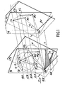
- FIG 1 there is shown an explanatory diagram of the tomography method according to the invention.
- An object 0 is irradiated by means of a beam F of X or y rays parallel to it.
- a section S of the object O defined by the intersection of this object 0 by a plane P2, as well as a straight line ⁇ 2 intersecting the plane P 2 at a point D 2 .
- the plane P 2 and the line ⁇ 2 are transformed respectively into the plane P 1 and into the line ⁇ 1 which intersects the plane P l at a point D l .
- a rotation of angle a of the object 0 is then carried out around the line ⁇ 2 .
- the plane P 2 , the point A 2 , the point B 2 and the point C 2 are transform respectively into the plane P ' 2 , the point A' 2 , the point B ' 2 and the point C' 2 , the new position of the section S following this rotation being identified in Figure 1 by the surface s contained in plane P 2 and of course containing points A ' 2 and B' 2 .
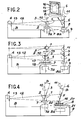
- FIG. 2 there is shown schematically a particular embodiment of the device object of the invention, for performing a tomography of an object 1 according to a section 2 thereof identified in advance and contained in a plane 3, the trace of which is seen in FIG. 2.
- the device essentially comprises, on a frame B, a fixed source 4 of radiation, a film 5 sensitive to this radiation and also contained in a plane 6, the trace of which is seen in the figure. 2, a first plate 7 and a second plate 8 arranged horizontally and serving respectively as supports for the object 1 and for the film 5, and a geared motor 9 able to rotate in the same direction and at the same constant speed, this is that is to say synchronously, the plates 7 and 8 around their respective axes 10 and 11 vertical and parallel.
- the axis 10 of the first plate 7 is called the first axis
- the axis 11 of the second plate 8 is called the second axis.
- the radiation source 4 is chosen so as to be as punctual as possible. Insofar as it is desired to carry out a fine densitometric examination of the image thus obtained, it is desirable to choose a source of radiation that is as monochromatic as possible. ble, or a polychromatic radiation source associated with a wavelength filter. Otherwise, a continuous radiation source alone may be very suitable.
- the source 4 is an X-ray generator marketed by the BALTEAU Company, of variable operating voltage from 50 kV to 400 kV, with continuous radiation, having a dose rate in the axis of the beam produced from 50 rads / min at 1 m and having a focal point of the order of 0.7 mm in diameter.
- the film 5 is an X-ray film for X-rays, of type A or M, sold by the company KODAK, which can be used naked or mounted in an envelope.
- the geared motor 9 comprises a direct current motor coupled to a reduction gear, the speed of which can be varied from -1 rpm to 10 rpm.
- the relative arrangement of the source 4 and of the geared motor 9 is such that the object 1, maintained on the first plate 7, is interposed between the source 4 and the film 5 maintained on the second plate 8.
- the source 4 is arranged in the plane containing the axes 10 and 11, so as to send its radiation 12 on the object 1 when it is operating.
- the source 4 can be adjustable in height to optimize the adjustment of the tomography device.
- the geared motor 9 is provided with members 7a and 8a which can be produced by those skilled in the art, allowing respectively the adjustment of the height of the plates 7 and 8, that is to say the displacement of the latter parallel to the axes 10 and 11, in order to correctly position the object 1 in height relative to the film 5, so as to be able to obtain on this film 5, when desired, a complete image of the section 2 examined, the size of the film 5 being then also suitably chosen.
- the members 7a and 8a can also be provided for adjusting the spacing between the axes 10 and 11.
- a diaphragm 13 is placed in front of the source 4 to avoid diffusion of the radiation which it emits, in the place where the tomography device. If necessary, and to improve the quality of the reproduction of the section of the object on the film, it is also possible to interpose a diaphragm between the object 1 and the film 5.
- the distance between the source 4 and the object 1 is chosen to be as large as possible in order to limit the magnification factor which results in the appearance of a "geometric blur".
- the distance between the film 5 and the object 1 is chosen to be as small as possible, but in any case depends on the dimensions of the object 1 to be examined.
- a magnification factor of the order of 1.1 seems to be a good compromise, noting that the geometric blur is not dependent on the magnification factor as such, but on the variation of the magnification factor that each of the elements undergoes. of the surface of the section of the object 1 to be represented when this object and the film 5 rotate on themselves.
- the relative arrangement of the object 1 and of the film 5 on their respective plates 7 and 8 is chosen in such a way that the plane 6 of the film 5 is the homothetic of the plane 3 of section 2 of which it is desired to form the image 14 on the film 5, by the homothety having for center the source 4 and transforming the first axis 10 into the second axis 11.
- the film 5 is mounted on a frame 15 and held on this frame 15 by means of clips 16.
- the frame 15 is fixed on the second plate 8 so that the plane 6 of the film 5 is vertical and contains the second axis 11.
- the object 1 is then placed on the first plate 7 so that the first axis 10 intersects the object 1 and that the plane 3 containing the section 2 studied also contains the first axis 10 and is parallel to the film 5.
- on this film 5 is formed the image of the intersection of the object 1 and the vertical plane parallel to the film 5 and containing the axis 10 of the first plateau 7, said intersection then not necessarily being identified in advance.
- the plates 7 and 8 and the clamps 16 are preferably made using materials having, with respect to the radiation used, an absorption much lower than that of the object 1 studied.
- the second plate 8 could be provided with displacement means comparable to the means 17, for moving the frame 16 and therefore the film 5, perpendicular to the axes 10 and 11, so as to properly position the film and no longer the object to form on the film the image of the desired section, this film 5 of course remaining vertical.
- FIG 4 there is shown schematically another particular embodiment of the tomography device object of the invention. It is made by adding to the device shown in Figure 2 means 20 for moving the frame 16 and therefore the film 5, on the second plate 8, perpendicular to the second axis 11. It is for example a displacement carriage adjustable by screw 21, carriage to which the frame 16 is made integral. Also added to these means 20 are means 22 for tilting the frame 16 and therefore the film 5, relative to the second axis 11. More precisely, these means 21 tilt, achievable by those skilled in the art, carry the frame 16 and are mounted on the displacement means 20.
- displacement means 20 and the tilting means 22 make it possible to form on the film 5 the image of a section 2 of the object 1 maintained on its plate 7, section whose plane 3 forms an angle 5, between 0 ° and 90 °, with the first axis 10: one acts on the means 20 of displacement and on the means 22 of tilting to make the plane 6 of the film 5 homothetic to the plane 3 of section 2, in the homothetic having for center the source 4 and transforming the first axis 10 into the second axis ll, the plane 6 of the film 5 then making the same angle 13 with the second axis 11.
- the first plate 7 could also be provided with means for moving and tilting the object 1, which would be comparable to the means 20 and 22 above, and on which one would act to correctly position the object 1 relative to the film 5 which could then retain the position it occupies in FIG. 2 in which the plane 6 of the film contains the axis 11 of the second plate 8. In certain cases, it could even be convenient to act both on the means for moving and tilting the object and the film to obtain the desired relative position for the latter.
- the source 4 of radiation could of course be a source of photons y or other penetrating radiation, for example neutrons or electronics, the film 5 then being adapted to this radiation.
- the word "film” is moreover taken with the general meaning of "surface sensitive to radiation”.
- a source of X or y photons with a plane scintillator constituting said sensitive surface, this scintillator, made of cesium iodide for example, being itself followed by a plane photographic film, parallel to said scintillator and placed with the latter in an envelope opaque to light.
- the invention allows the control of parts made of materials whose absorption coefficients are different from each other and are more clearly greater than those of the human body, something which is very difficult to achieve with the tomography devices of the prior art, intended for medical domain.
Landscapes
- Health & Medical Sciences (AREA)
- Engineering & Computer Science (AREA)
- Nuclear Medicine, Radiotherapy & Molecular Imaging (AREA)
- Pulmonology (AREA)
- Radiology & Medical Imaging (AREA)
- Theoretical Computer Science (AREA)
- Physics & Mathematics (AREA)
- Life Sciences & Earth Sciences (AREA)
- Chemical & Material Sciences (AREA)
- Analytical Chemistry (AREA)
- Biochemistry (AREA)
- General Health & Medical Sciences (AREA)
- General Physics & Mathematics (AREA)
- Immunology (AREA)
- Pathology (AREA)
- Analysing Materials By The Use Of Radiation (AREA)
- Apparatus For Radiation Diagnosis (AREA)
Applications Claiming Priority (2)
| Application Number | Priority Date | Filing Date | Title |
|---|---|---|---|
| FR8221319 | 1982-12-20 | ||
| FR8221319A FR2538114A1 (fr) | 1982-12-20 | 1982-12-20 | Procede et dispositif de tomographie a film |
Publications (1)
| Publication Number | Publication Date |
|---|---|
| EP0115721A1 true EP0115721A1 (fr) | 1984-08-15 |
Family
ID=9280273
Family Applications (1)
| Application Number | Title | Priority Date | Filing Date |
|---|---|---|---|
| EP83402423A Withdrawn EP0115721A1 (fr) | 1982-12-20 | 1983-12-14 | Procédé et dispositif de tomographie |
Country Status (3)
| Country | Link |
|---|---|
| EP (1) | EP0115721A1 (enExample) |
| JP (1) | JPS59116040A (enExample) |
| FR (1) | FR2538114A1 (enExample) |
Cited By (2)
| Publication number | Priority date | Publication date | Assignee | Title |
|---|---|---|---|---|
| DE19542762A1 (de) * | 1995-11-16 | 1997-05-22 | Joerg Dr Habersetzer | Manipulator für verschiedene Tomographieverfahren |
| CN116583744A (zh) * | 2020-12-07 | 2023-08-11 | 斯格瑞公司 | 使用透射x射线源的高产量3D x射线成像系统 |
Families Citing this family (2)
| Publication number | Priority date | Publication date | Assignee | Title |
|---|---|---|---|---|
| US7099432B2 (en) | 2003-08-27 | 2006-08-29 | Matsushita Electric Industrial Co., Ltd. | X-ray inspection apparatus and X-ray inspection method |
| DE102010010723B4 (de) * | 2010-03-09 | 2017-05-04 | Yxlon International Gmbh | Verwendung einer Laminographieanlage |
Citations (6)
| Publication number | Priority date | Publication date | Assignee | Title |
|---|---|---|---|---|
| DE693374C (de) * | 1938-06-27 | 1940-07-12 | C H F Mueller Akt Ges | Verfahren zur Herstellung von Koerperschnittbildern mittels Roentgenstrahlen |
| FR1118076A (fr) * | 1953-11-14 | 1956-05-31 | Philips Nv | Appareil pour la radioscopie tomographique avec renforçateur d'images |
| DE972794C (de) * | 1952-01-15 | 1959-09-24 | Johann Dumer | Geraet zur roentgenographischen Darstellung von Koerperschnitten |
| FR1511590A (fr) * | 1966-12-12 | 1968-02-02 | G Pi Giprozdrav | Installation pour les investigations par rayons x, notamment en tomographie |
| US4000425A (en) * | 1975-08-01 | 1976-12-28 | Craig Dwin R | Apparatus for producing axial tomograms |
| GB1582833A (en) * | 1976-04-28 | 1981-01-14 | Emi Ltd | Radiography |
-
1982
- 1982-12-20 FR FR8221319A patent/FR2538114A1/fr active Granted
-
1983
- 1983-12-14 EP EP83402423A patent/EP0115721A1/fr not_active Withdrawn
- 1983-12-19 JP JP58239597A patent/JPS59116040A/ja active Pending
Patent Citations (6)
| Publication number | Priority date | Publication date | Assignee | Title |
|---|---|---|---|---|
| DE693374C (de) * | 1938-06-27 | 1940-07-12 | C H F Mueller Akt Ges | Verfahren zur Herstellung von Koerperschnittbildern mittels Roentgenstrahlen |
| DE972794C (de) * | 1952-01-15 | 1959-09-24 | Johann Dumer | Geraet zur roentgenographischen Darstellung von Koerperschnitten |
| FR1118076A (fr) * | 1953-11-14 | 1956-05-31 | Philips Nv | Appareil pour la radioscopie tomographique avec renforçateur d'images |
| FR1511590A (fr) * | 1966-12-12 | 1968-02-02 | G Pi Giprozdrav | Installation pour les investigations par rayons x, notamment en tomographie |
| US4000425A (en) * | 1975-08-01 | 1976-12-28 | Craig Dwin R | Apparatus for producing axial tomograms |
| GB1582833A (en) * | 1976-04-28 | 1981-01-14 | Emi Ltd | Radiography |
Cited By (3)
| Publication number | Priority date | Publication date | Assignee | Title |
|---|---|---|---|---|
| DE19542762A1 (de) * | 1995-11-16 | 1997-05-22 | Joerg Dr Habersetzer | Manipulator für verschiedene Tomographieverfahren |
| DE19542762C2 (de) * | 1995-11-16 | 1998-01-22 | Joerg Dr Habersetzer | Tomographieverfahren und Anordnung zur Erzeugung von großflächigen Tomogrammen |
| CN116583744A (zh) * | 2020-12-07 | 2023-08-11 | 斯格瑞公司 | 使用透射x射线源的高产量3D x射线成像系统 |
Also Published As
| Publication number | Publication date |
|---|---|
| JPS59116040A (ja) | 1984-07-04 |
| FR2538114A1 (fr) | 1984-06-22 |
| FR2538114B1 (enExample) | 1985-05-10 |
Similar Documents
| Publication | Publication Date | Title |
|---|---|---|
| EP0292402B1 (fr) | Procédé et dispositif d'imagerie tridimensionelle à partir de mesures bidimensionnelles de l'atténuation d'un rayonnement | |
| FR2718942A1 (fr) | Appareil de radiodiagnostic. | |
| FR2924325A1 (fr) | Appareil de radiologie dentaire et procede associe. | |
| FR2505169A1 (fr) | Appareil medical a mouvements multiples | |
| FR2938182A1 (fr) | Appareil de radiologie dentaire et procede d'utilisation associe | |
| FR2938183A1 (fr) | Appareil de radiologie dentaire panoramique et procede d'utilisation associe | |
| FR2491250A1 (fr) | Balayage a point mobile a grandeur de champ arbitrairement forme | |
| FR2491629A1 (fr) | Dispositif de radioscopie pour l'enregistrement d'images de couches d'un objet tridimensionnel | |
| FR2630903A1 (fr) | Dispositif de tomographie a grande cadence d'acquisition | |
| FR2877829A1 (fr) | Configuration de balayage a fentes reposant sur un detecteur a panneau plat. | |
| EP1360475A1 (fr) | Dispositif et procede de manipulation d'un produit et de traitement d'images radioscopiques du produit pour obtenir des coupes tomographiques et utilisations | |
| FR2508790A1 (fr) | Appareil de diagnostic a rayonnement | |
| WO2014096705A1 (fr) | Dispositif d'éclairage par balayage, dispositif d'imagerie le comportant et procédé de mise en oeuvre | |
| FR3073290A1 (fr) | Dispositif et procede d'inspection tridimensionnelle d'un objet par rayons x | |
| EP3368919B1 (fr) | Collimateur tournant pour determiner la position d'un element muni de capteurs dans un systeme d'imagerie par rayons x | |
| EP0115721A1 (fr) | Procédé et dispositif de tomographie | |
| FR3028168A1 (fr) | Appareil de tomographie numerique et procede associe | |
| EP0800655B1 (fr) | Methode et dispositif pour determiner au moins un parametre caracteristique d'un corps | |
| EP0600014B1 (fr) | Procede et appareil de determination de la position exacte d'une cible a l'aide d'un dispositif de reception comprenant une partie active lineaire formee d'une multiplicite d'elements discrets sensibles aux rayonnements | |
| EP0001523B1 (fr) | Procédé et appareil de tomographie axiale transverse | |
| EP0431989A1 (fr) | Appareil de radiologie avec filtre d'homogénéisation | |
| EP0226484B1 (fr) | Appareil de radiologie à balayage | |
| EP0112203B1 (fr) | Appareil d'imagerie médicale permettant la tomographie longitudinale | |
| FR2657771A1 (fr) | Appareil de radiologie avec diaphragme a ouverture automatique. | |
| CA2006191A1 (fr) | Table de support patient pour examens sur installations de scintigraphie |
Legal Events
| Date | Code | Title | Description |
|---|---|---|---|
| PUAI | Public reference made under article 153(3) epc to a published international application that has entered the european phase |
Free format text: ORIGINAL CODE: 0009012 |
|
| AK | Designated contracting states |
Designated state(s): AT BE CH DE IT LI NL SE |
|
| 17P | Request for examination filed |
Effective date: 19850118 |
|
| STAA | Information on the status of an ep patent application or granted ep patent |
Free format text: STATUS: THE APPLICATION IS DEEMED TO BE WITHDRAWN |
|
| 18D | Application deemed to be withdrawn |
Effective date: 19860703 |
|
| RIN1 | Information on inventor provided before grant (corrected) |
Inventor name: RULMONT, FRANCIS Inventor name: AMAURY, HENRI |