EP0114775A2 - Fang- und Führungseinrichtung für Flugzeug - Google Patents
Fang- und Führungseinrichtung für Flugzeug Download PDFInfo
- Publication number
- EP0114775A2 EP0114775A2 EP84400115A EP84400115A EP0114775A2 EP 0114775 A2 EP0114775 A2 EP 0114775A2 EP 84400115 A EP84400115 A EP 84400115A EP 84400115 A EP84400115 A EP 84400115A EP 0114775 A2 EP0114775 A2 EP 0114775A2
- Authority
- EP
- European Patent Office
- Prior art keywords
- barrier
- group
- stopper
- aircraft
- elements
- Prior art date
- Legal status (The legal status is an assumption and is not a legal conclusion. Google has not performed a legal analysis and makes no representation as to the accuracy of the status listed.)
- Granted
Links
Images

Classifications
-
- B—PERFORMING OPERATIONS; TRANSPORTING
- B64—AIRCRAFT; AVIATION; COSMONAUTICS
- B64F—GROUND OR AIRCRAFT-CARRIER-DECK INSTALLATIONS SPECIALLY ADAPTED FOR USE IN CONNECTION WITH AIRCRAFT; DESIGNING, MANUFACTURING, ASSEMBLING, CLEANING, MAINTAINING OR REPAIRING AIRCRAFT, NOT OTHERWISE PROVIDED FOR; HANDLING, TRANSPORTING, TESTING OR INSPECTING AIRCRAFT COMPONENTS, NOT OTHERWISE PROVIDED FOR
- B64F1/00—Ground or aircraft-carrier-deck installations
- B64F1/22—Ground or aircraft-carrier-deck installations for handling aircraft
Definitions
- the subject of the present invention is a stop and guide barrier for aircraft, of the type comprising a stopper carrying a guide pattern and against which the windshield of the passenger compartment of an aircraft coming to be positioned at right must be brought. a passenger landing bridge, or a specific point on an aeronautical platform.
- the present invention aims to remedy these drawbacks, which goal is achieved in that it provides a barrier consisting of several elements mounted end to end and articulated with respect to each other, one of the end elements. being extended by the stopper carrying the test pattern and the opposite end element being received in a support structure, said barrier comprising a first group of means adapted to allow the displacement of the stopper in three dimensions and a second group of means being provided for selectively actuating the means of said first group as a function of the particular characteristics of the expected aircraft.
- the first group of means is adapted to allow the rotation of the barrier respectively about an axis perpendicular to the plane on which the support structure rests, its pivoting on either side of a vertical axis in a parallel plane. to the longitudinal axis of the aircraft and the extension or retraction of its elements relative to each other
- the means belonging to the first group and allowing the rotation of the barrier comprise an orientation ring interposed between the support structure and the end element opposite to that which carries the stopper.
- this slewing ring allows rotation through 180 °, a greater angle being unnecessary.
- the means belonging to the first group and allowing respectively the pivoting of the barrier and the extension and the folding of the elements with respect to each other they can be constituted by any actuating member with reversible effect.
- any actuating member with reversible effect such as a jack or a ball joint subjected to the drive of an electric motor, with reduction gear.
- the pivoting of the barrier can be done on 90 ° on each side of the vertical axis, which gives a range of 180 °.
- the barrier takes the form of a finger, the elements of which constitute the knuckles.
- the movements of extension and retraction of the barrier are, in this case, similar to those of a finger.
- the stopper is mounted on the end element on which it depends by means of a device ensuring the horizontal maintenance of this stopper, whatever the position of the elements of the fence.
- the stopper carries a double guide pattern correcting the parallax error caused by the spacing between the seats of the pilot and co-pilot, and therefore between the observation points of the test patterns, which vary according to the type of aircraft.
- the first group of means according to the invention preferably comprises means making it possible to vary the spacing between the test patterns.
- the end element extended by the stopper be telescopic.
- the second group of means selectively actuating the means of the first group as a function of the particular characteristics of the expected aircraft is advantageously constituted, on the one hand, by a servo-control in the memory of which the methods of actuation of each are stored.
- means of the first group (rotation, pivoting, extension of the elements of the barrier; spacing of the test patterns) according to each type of aircraft and, on the other hand, a central under the control of this servo-control and capable of 'act on the means of the first group.
- the operating principle of the assembly is that, when the servo-control receives an order corresponding to a type of aircraft, it acts accordingly on the control unit so that the latter brings the stopper carrying the test pattern into the position wanted. It is of course provided security which will be described briefly below.
- this target is cylindrical and that the useful part of this target affects all its. periphery.
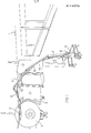
- FIGS. 1 and 2 If one refers to FIGS. 1 and 2, one sees an airplane 1 stopped along a fixed building comprising two pre-gangways 2 one of which is opposite the door (not visible on the figure) of the airplane and connected to this door by a bellows 3.
- the windshield of the passenger compartment of the airplane is pressed against a stopper 4 made of light alloy or fibers carrying a double guide pattern to variable spacing and which depends on the barrier according to the invention.
- the double target is cylindrical and its useful surface extends over its entire periphery, which avoids having to maintain its orientation such that its useful surface is always suitably directed towards the pilot and the co-pilot of the aircraft. expected.
- the stopper 4 occupies a completely different position depending on the model of the aircraft.
- Its base consists of a steel column 5 provided with reinforcements and whose height depends on where it is placed relative to the pre-gangways 2.
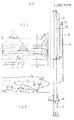
- a tray provided with rack wheels or an oricntion crown 6 which allows the entire barrier to rotate through 180 °.
- a tilting device 7 comprised between two blanks provided with stiffeners having a shape inspired by that of the turret of a tank, and which consists of a jack whose end acts on cams of suitable profile.
- This device allows the barrier to tilt or pivot on either side of the vertical axis at an angle of 90 °, or in total 180 °, in a plane parallel to the longitudinal axis of the aircraft.
- the actual barrier takes the form of a finger with four phalanges 9, 10, 11 and 12 made of steel or light alloy mounted end to end and articulated with respect to each other. At each joint, there is provided a hydraulic cylinder, respectively, 13, 14 and 15, bearing on the adjacent ends of each pair of knuckles.
- the first phalanx is 2 m long, the second 3.60 m, the third 3.50 m and the fourth, which is telescopic, a length varying between 2 m and 3.50 m .
- the 2nd, 3rd and 4th phalanxes work in planes perpendicular to the longitudinal axis of the plane.
- the 4th phalanx 12 is extended by the stopper 4, which is mounted on the phalanx by means of a crown 16 allowing, whatever the position of the elements of the barrier, to have the stopper 4 always parallel to the ground, that is to say in the axis of the passenger compartment of the aircraft.
- the 3rd and 4th phalanges are not in alignment with the other two.
- a separate control device for the barrier according to the invention is provided, a device which comprises a hydraulic unit and a servo-control which will be described in principle with regard to the operation of the barrier.
- the barrier being in the rest position indicated above, when an aircraft is signaled to the display, a contact is created at the level of the logic and the corresponding information passes through a comparator whose role is to analyze whether the information in question is accurate or not, before it is translated into orders acting on the hydraulic power unit and therefore causing the barrier to deploy.
- the comparator gives the necessary orders to the servo-control which, on the one hand, acts on the hydraulic power unit to unfold the barrier and, on the other hand, triggers a search sequence for the desired location for the stopper 4 and the desired spacing for the test patterns; this spacing can be obtained by means of a jack acting on a system of telescopic tubes.
- the barrier is deployed as follows: the stopper assembly 4 / 4th and 3rd phalanxes 11 and 12 pivots by a block on the end of the 2nd phalanx 10, the 4th phalanx 12 and the stopper 4 then pivot by a block on the end of the 3rd phalanx 11 and, finally, the stopper 4 pivots on the end of the 4th phalanx 12.
- a safety system is provided which either compensates for minor leaks or triggers a "danger" signal "if the leak is not compensable.
- contacts provided on the barrier send information to the comparator which, after analysis, accepts or refuses the positioning. If the positioning is refused, the comparator sends the information necessary for the correction of positioning with servo-control and the cycle is repeated.
- the aircraft can come to line up along said building, the system of guidance sights provided on the stopper 4 allowing both the pilot and the co-pilot to align the aircraft and to advance it until the passenger compartment comes into contact with the stopper 4.
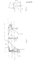
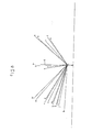
- FIGS 4, 5, 7 and 8 show different possible positions of the barrier depending on the type of aircraft.
- these aircraft are identified as follows:
- the present invention is not limited to the embodiment described and shown.
- the support structure could not be fixed to the ground but, for example, on a pre-gangway, in which case column 5 could possibly be eliminated, this having only a height compensation role.
Landscapes
- Engineering & Computer Science (AREA)
- Mechanical Engineering (AREA)
- Aviation & Aerospace Engineering (AREA)
- Aerodynamic Tests, Hydrodynamic Tests, Wind Tunnels, And Water Tanks (AREA)
- Traffic Control Systems (AREA)
- Position Fixing By Use Of Radio Waves (AREA)
- Control Of Position Or Direction (AREA)
Applications Claiming Priority (2)
| Application Number | Priority Date | Filing Date | Title |
|---|---|---|---|
| FR8300981A FR2539704A1 (fr) | 1983-01-24 | 1983-01-24 | Barriere d'arret et de guidage pour aeronefs |
| FR8300981 | 1983-01-24 |
Publications (3)
| Publication Number | Publication Date |
|---|---|
| EP0114775A2 true EP0114775A2 (de) | 1984-08-01 |
| EP0114775A3 EP0114775A3 (en) | 1984-08-15 |
| EP0114775B1 EP0114775B1 (de) | 1986-10-22 |
Family
ID=9285199
Family Applications (1)
| Application Number | Title | Priority Date | Filing Date |
|---|---|---|---|
| EP84400115A Expired EP0114775B1 (de) | 1983-01-24 | 1984-01-20 | Fang- und Führungseinrichtung für Flugzeug |
Country Status (5)
| Country | Link |
|---|---|
| US (1) | US4568046A (de) |
| EP (1) | EP0114775B1 (de) |
| DE (1) | DE3461021D1 (de) |
| FR (1) | FR2539704A1 (de) |
| SU (1) | SU1433402A3 (de) |
Family Cites Families (9)
| Publication number | Priority date | Publication date | Assignee | Title |
|---|---|---|---|---|
| US2842876A (en) * | 1955-08-02 | 1958-07-15 | Johnson Fare Box Co | Parking lot control system |
| US3003451A (en) * | 1959-09-10 | 1961-10-10 | Gen Precision Inc | Mirror landing system |
| US3487553A (en) * | 1967-03-22 | 1970-01-06 | Trans Meridian Intern Inc | Vtol aircraft flight system |
| US3674226A (en) * | 1970-04-06 | 1972-07-04 | Federal Sign And Signal Corp | Aircraft parking method and means |
| US3626884A (en) * | 1970-08-07 | 1971-12-14 | Us Navy | Landing aid alignment mast |
| US3690599A (en) * | 1971-03-11 | 1972-09-12 | Ira Vincent Hager | Aircraft docking guide |
| US3729262A (en) * | 1971-07-20 | 1973-04-24 | Burroughs Corp | Optical lens docking system |
| US4249159A (en) * | 1977-10-17 | 1981-02-03 | Stasko Thomas A | Aircraft docking system |
| US4236686A (en) * | 1978-09-07 | 1980-12-02 | Grumman Aerospace Corporation | Ship compatible launch, retrieval and handling system for (VTOL) aircraft |
-
1983
- 1983-01-24 FR FR8300981A patent/FR2539704A1/fr active Granted
-
1984
- 1984-01-20 DE DE8484400115T patent/DE3461021D1/de not_active Expired
- 1984-01-20 EP EP84400115A patent/EP0114775B1/de not_active Expired
- 1984-01-20 US US06/572,238 patent/US4568046A/en not_active Expired - Fee Related
- 1984-01-24 SU SU843699110A patent/SU1433402A3/ru active
Also Published As
| Publication number | Publication date |
|---|---|
| DE3461021D1 (en) | 1986-11-27 |
| EP0114775A3 (en) | 1984-08-15 |
| SU1433402A3 (ru) | 1988-10-23 |
| FR2539704A1 (fr) | 1984-07-27 |
| US4568046A (en) | 1986-02-04 |
| EP0114775B1 (de) | 1986-10-22 |
| FR2539704B1 (de) | 1985-04-26 |
Similar Documents
| Publication | Publication Date | Title |
|---|---|---|
| EP3210660B1 (de) | Drohne mit zusammenklappbaren verbindungsarmen | |
| EP1777494B1 (de) | System zur Bestimmung der Lage einer 3D Koordinatenmessmaschine oder einer Bearbeitungsmaschine in einem ortsfesten Bezugssystem | |
| CA1282040C (fr) | Dispositif de transfert de chargement, en particulier pour le transfert rapide de charges palettisees | |
| EP2433085B1 (de) | Dreidimensionale messvorrichtung | |
| EP2155553B1 (de) | Vorrichtung zur steuerung der blätter eines helikopters oder eines ähnlichen fluggerätes | |
| EP0341134B1 (de) | System zum Ausführen von Arbeiten auf grossmassigen Gegenständen, z.B. zum Anstreichen eines Flugzeuges | |
| FR2587784A1 (fr) | Structure extensible et retractable a plan orientable | |
| FR2631548A1 (fr) | Module autonome de soins intensifs et de reanimation | |
| FR2948096A1 (fr) | Train avant d'aeronef a dispositif de commande unique pour le relevage et la direction | |
| FR3048186A1 (fr) | Drone ayant des supports de drone relevables | |
| EP1666833B1 (de) | Motorisierter und orientierbarer Messkopf | |
| EP0019558B1 (de) | Scherenhebetisch mit Verschiebungsmöglichkeit | |
| FR2643610A1 (fr) | Atterrisseur d'avion a roues orientables lors du relevage de l'atterrisseur | |
| EP0114775B1 (de) | Fang- und Führungseinrichtung für Flugzeug | |
| FR2718777A1 (fr) | Dispositif de coffrage à banches. | |
| EP0100926A1 (de) | Fahrzeug zur Handhabung von Materialien mit orientierbarem Ausleger und eingebautem Stabilisiergestell | |
| EP0362063B1 (de) | Brückenlegefahrzeug | |
| FR2948095A1 (fr) | Verin double fonction direction et relevage pour train d'aterrissage avant | |
| FR2573724A1 (fr) | Procede et dispositif opto-electronique permettant a une structure mobile de suivre les deplacements d'une autre structure. | |
| EP0423013A1 (de) | System zur Steuerung eines beweglichen Armes, verbunden mit einem Fahrzeug zur Überwindung von Graten | |
| EP1072366A1 (de) | Fördereinrichtung | |
| FR3079768A1 (fr) | Robot destine a ecrire sur une surface | |
| FR2707947A1 (fr) | Train d'atterrissage d'aéronef, du type à relevage latéral. | |
| EP0052029B1 (de) | Baukastenanordnung zur automatischen Massüberwachung drehender Stücke | |
| FR2683295A1 (fr) | Appareil de pose automatique d'un joint dans le nez de robinet d'une bouteille de gaz. |
Legal Events
| Date | Code | Title | Description |
|---|---|---|---|
| PUAI | Public reference made under article 153(3) epc to a published international application that has entered the european phase |
Free format text: ORIGINAL CODE: 0009012 |
|
| PUAL | Search report despatched |
Free format text: ORIGINAL CODE: 0009013 |
|
| AK | Designated contracting states |
Designated state(s): BE CH DE GB IT LI NL |
|
| AK | Designated contracting states |
Designated state(s): BE CH DE GB IT LI NL |
|
| 17P | Request for examination filed |
Effective date: 19850212 |
|
| 17Q | First examination report despatched |
Effective date: 19860401 |
|
| GRAA | (expected) grant |
Free format text: ORIGINAL CODE: 0009210 |
|
| AK | Designated contracting states |
Kind code of ref document: B1 Designated state(s): BE CH DE GB IT LI NL |
|
| REF | Corresponds to: |
Ref document number: 3461021 Country of ref document: DE Date of ref document: 19861127 |
|
| ITF | It: translation for a ep patent filed | ||
| PLBE | No opposition filed within time limit |
Free format text: ORIGINAL CODE: 0009261 |
|
| STAA | Information on the status of an ep patent application or granted ep patent |
Free format text: STATUS: NO OPPOSITION FILED WITHIN TIME LIMIT |
|
| 26N | No opposition filed | ||
| REG | Reference to a national code |
Ref country code: GB Ref legal event code: 732 |
|
| REG | Reference to a national code |
Ref country code: GB Ref legal event code: 732 |
|
| BECA | Be: change of holder's address |
Free format text: 890202 *SOVAM INDUSTRIES:CHATILLON SUR THOUET, F-79200 PARTHENAY |
|
| REG | Reference to a national code |
Ref country code: CH Ref legal event code: PUE Owner name: SOVAM INDUSTRIES |
|
| NLS | Nl: assignments of ep-patents |
Owner name: SOVAM INDUSTRIES TE PARTHENAY, FRANKRIJK. |
|
| ITTA | It: last paid annual fee | ||
| PGFP | Annual fee paid to national office [announced via postgrant information from national office to epo] |
Ref country code: BE Payment date: 19921230 Year of fee payment: 10 |
|
| PGFP | Annual fee paid to national office [announced via postgrant information from national office to epo] |
Ref country code: GB Payment date: 19930108 Year of fee payment: 10 |
|
| PGFP | Annual fee paid to national office [announced via postgrant information from national office to epo] |
Ref country code: CH Payment date: 19930128 Year of fee payment: 10 |
|
| PGFP | Annual fee paid to national office [announced via postgrant information from national office to epo] |
Ref country code: NL Payment date: 19930131 Year of fee payment: 10 |
|
| PGFP | Annual fee paid to national office [announced via postgrant information from national office to epo] |
Ref country code: DE Payment date: 19930226 Year of fee payment: 10 |
|
| PG25 | Lapsed in a contracting state [announced via postgrant information from national office to epo] |
Ref country code: GB Effective date: 19940120 |
|
| PG25 | Lapsed in a contracting state [announced via postgrant information from national office to epo] |
Ref country code: LI Effective date: 19940131 Ref country code: CH Effective date: 19940131 Ref country code: BE Effective date: 19940131 |
|
| BERE | Be: lapsed |
Owner name: SOVAM INDUSTRIES Effective date: 19940131 |
|
| PG25 | Lapsed in a contracting state [announced via postgrant information from national office to epo] |
Ref country code: NL Effective date: 19940801 |
|
| GBPC | Gb: european patent ceased through non-payment of renewal fee |
Effective date: 19940120 |
|
| NLV4 | Nl: lapsed or anulled due to non-payment of the annual fee | ||
| REG | Reference to a national code |
Ref country code: CH Ref legal event code: PL |
|
| PG25 | Lapsed in a contracting state [announced via postgrant information from national office to epo] |
Ref country code: DE Effective date: 19941001 |