EP0114543B1 - Dispositif d'orientation omnidirectionnelle d'une antenne - Google Patents
Dispositif d'orientation omnidirectionnelle d'une antenne Download PDFInfo
- Publication number
- EP0114543B1 EP0114543B1 EP83402362A EP83402362A EP0114543B1 EP 0114543 B1 EP0114543 B1 EP 0114543B1 EP 83402362 A EP83402362 A EP 83402362A EP 83402362 A EP83402362 A EP 83402362A EP 0114543 B1 EP0114543 B1 EP 0114543B1
- Authority
- EP
- European Patent Office
- Prior art keywords
- housing
- shells
- mast
- articulation
- fact
- Prior art date
- Legal status (The legal status is an assumption and is not a legal conclusion. Google has not performed a legal analysis and makes no representation as to the accuracy of the status listed.)
- Expired
Links
- 230000001681 protective effect Effects 0.000 claims description 15
- 230000000712 assembly Effects 0.000 claims description 6
- 238000000429 assembly Methods 0.000 claims description 6
- 238000005192 partition Methods 0.000 description 3
- 229920000297 Rayon Polymers 0.000 description 2
- 230000000903 blocking effect Effects 0.000 description 2
- 239000002964 rayon Substances 0.000 description 2
- 230000000295 complement effect Effects 0.000 description 1
- 230000002950 deficient Effects 0.000 description 1
- 230000005484 gravity Effects 0.000 description 1
- 238000009434 installation Methods 0.000 description 1
- 230000035515 penetration Effects 0.000 description 1
- 230000005855 radiation Effects 0.000 description 1
- 230000000284 resting effect Effects 0.000 description 1
- 238000003466 welding Methods 0.000 description 1
Images
Classifications
-
- H—ELECTRICITY
- H01—ELECTRIC ELEMENTS
- H01Q—ANTENNAS, i.e. RADIO AERIALS
- H01Q1/00—Details of, or arrangements associated with, antennas
- H01Q1/12—Supports; Mounting means
- H01Q1/125—Means for positioning
Definitions
- the present invention relates to the field of antenna supports.
- the present invention relates more specifically to an omnidirectional antenna orientation device.
- the most conventional antenna orientation devices consist of flanges and arcs cooperating to support the antennas. Such devices do not easily allow orientation of the omnidirectional antenna.
- Document DE-A-1 956 172 describes an antenna orientation device which comprises a housing rotatably mounted on a fixed mast around the axis thereof, an antenna support itself pivotally mounted on the housing around an axis perpendicular to the axis of the mast, a screw used to adjust the inclination of the antenna support relative to the housing, and locking means capable of locking the various elements in position settled.
- Document DE-A-1 956 172 does not describe in detail the structure of the casing / mast joint nor the means making it possible to adjust the orientation of the casing around the axis of the mast.
- the antenna support is pivotally supported on the housing by a pin passing through it.
- the antenna support also carries in rotation a rod parallel to the aforementioned pin, and provided with a threaded bore which receives the adjusting screw whose head rests against the casing. This device allows only very limited pivoting of the antenna support relative to the housing.
- Document DE-A-2 246 945 describes another antenna orientation device.
- This includes a tripod carrying at its upper part a cradle which receives the actual orientation mechanism.
- This mechanism comprises a crown resting on the cradle and free to pivot about a vertical axis relative to the cradle. The pivoting of the crown around the vertical axis is controlled by a threaded system.
- the mechanism also includes an antenna support pivotally mounted about a horizontal axis on the crown. The pivoting of the antenna support around the horizontal axis is controlled by another threaded system; this moves a drawer engaged with a fork secured to the antenna support.
- the device described in DE-A-2 246 945 only allows very limited pivoting of the antenna support relative to the housing.
- An object of the present invention is to provide an orientation device allowing fine adjustment of the orientation of the antenna in elevation and / or in azimuth.
- Another object of the present invention is to provide an antenna orientation device, which is both simple to handle and install, and economical, so that it can be used in the field known as "general public" .
- Another object of the present invention is to provide a particularly robust antenna orientation device, so that the assembly can be supported safely and durably, with precision, in the appropriate position chosen.
- the omnidirectional antenna orientation device in accordance with the present invention is particularly suitable for the support of parabolic antennas, the size of which makes any mounting operation difficult. with the devices previously proposed.
- the omni-directional orientation device of an antenna is of the type known per se from document DE-A-1 956 172 comprising a casing which is rotatably mounted on a fixed mast around the axis thereof, an antenna support itself pivotally mounted on the housing around an axis perpendicular to the axis of the mast, a screw used to adjust the inclination of the antenna support relative to the housing and blocking means able to lock said different elements in the adjusted position;
- the device according to the present invention is characterized in that the housing is formed by two perpendicular branches, including a first tubular branch by which the housing is mounted for rotation on the fixed mast, the antenna support itself being mounted rotating on the second branch of the casing, around the axis of this branch, that the device further comprises two identical adjustment assemblies, one associated with the mast / casing joint, the other with the casing joint / support, each adjustment assembly comprising a toothed crown secured to one of the elements of said articulations, and of a screw, in engagement with said
- the casing is composed of two symmetrical half-shells each having two wings perpendicular to each other, in a T, each of the two wings having a generally semi-cylindrical envelope, at least the first wing, which is connected to the middle of the second, at right angles, consisting of a semi-cylindrical wall, and each of the half-shells having at the level of their rectilinear edges, planar edges projecting outwardly, intended to come into respective support when the two half shells are brought into contact to form the housing.
- planar edges projecting outwardly on the wings of the half-shells are provided with orifices intended to receive assembly bolts when the two half-shells are brought into contact with one another. on the other at their planar edges.
- the locking means capable of locking the mast / casing joint are formed by assembly bolts engaged in orifices provided in the planar edges connected to the first wing of each half-shell, such so that when tightening said bolts, the half-shells forming the housing are tightened against the mast.
- the blocking means capable of locking the casing / support joint comprise a threaded member engaged in a through bore provided at the second branch of the casing, said threaded member being adapted to be tightened on two radial bearing surfaces provided respectively at each end of this second branch.
- the toothed ring is integral with the casing and the screw is carried by the mast; similarly, at the level of said adjustment assembly associated with the casing / support articulation, the toothed ring is integral with the casing and the screw is carried by the support.
- each adjustment assembly comprises a protective cage formed by two half-shells, integral with one of the elements of each articulation, said cage defining a housing capable of receiving the toothed crown free to rotate, thus that a chamber capable of receiving the screw free to rotate but immobilized in translation, in position adjacent to the crown.
- the ring gear is provided with straight teeth on its outer periphery and has at least one radial groove on its inner periphery, in which are intended to penetrate the contiguous planar edges of the two half-shells of the casing , in order to immobilize in rotation the ring gear and the casing.
- each half-shell of the protective cage consists of a flat surface in a ring, to which a cylindrical jacket is connected, a hollow body communicating with the interior of the cylindrical jacket for receive the screw when the half-shells of the protective cage are assembled, and fixing lugs.
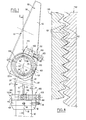
- the device for omnidirectional orientation of an antenna (not shown in the figures), in accordance with the present invention, comprises a casing 20 rotatably mounted on a fixed mast 10 , preferably vertical and which itself rotatably supports an antenna support 50.
- a casing 20 rotatably mounted on a fixed mast 10 , preferably vertical and which itself rotatably supports an antenna support 50.
- two identical adjustment assemblies are associated respectively with the mast 10 / housing 20 joint and the housing 20 / support 50 joint The purpose of such adjustment assemblies is to define with precision the relative position of each of the elements of the abovementioned joints.
- the adjustment assemblies have the general reference 100. More specifically, the adjustment assembly associated with the casing articulation 20 / support 50 will bear the reference 100A, while the adjustment assembly associated with the mast articulation 10 / casing 20 will bear the general reference 100B.
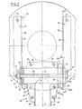
- the housing 20 is composed of two symmetrical half-shells 21, 21 ', each having two wings 22, 23 and 22', 23 'respectively, perpendicular to each other, and Each of the two wings 22, 23, 22 ', 23' has a generally semi-cylindrical envelope. More precisely, according to the embodiment shown in the figures, each of the two wings is formed of a semi-cylindrical wall, the axes of which are respectively referenced 0-0 and P-P in FIG. 2.
- the two semi-cylindrical walls constituting respectively the wings 22, 22 'and 23, 23' preferably have the same radius of curvature.
- the wings 22 and 22 'of the half-shells 21, 21', intended to form in cooperation a first branch of the casing 20, during the assembly of said half-shells, are connected to the middle of the wings 23, 23 '.
- each of the half-shells 21, 21 ' present at level of the rectilinear edges of its walls, of the flat edges, referenced 24, 25, 26 and 24 ', 25' and 26 'in the figures, which extend outwardly from the aforementioned semi-cylindrical envelopes. More specifically, the planar edges 24, 25, 26 and 24 ', 25' and 26 'are provided so that their outer surface, visible on the left half-view of FIG. 2, is located in the plane common to the axes 0-0 and PP mentioned above, that is to say on the plane defined by said semi-cylindrical envelope.
- the planar edges 24, 25, 26 and 24', 25 ', 26' provided respectively on each of the two half-shells come into respective support.
- planar edges 24, 25, 26 and 24 ', 25' and 26 'projecting outwards is provided with orifices referenced 27 (shown in FIG. 2) which are intended to receive assembly bolts (not shown) when the two half-shells 21, 21 'are brought into contact with one another at their flat edges 24, 25, 26 and 24', 25 ', 26'.
- the assembly of the two half-shells 21, 21 ' can be carried out by welding.
- the upper end of the fixed mast is engaged in the casing 20, at least over the entire length of the first branch of axis 0-0 formed by the wings 22 and 22 'mentioned above.
- the axis 15 of the mast 10 then corresponds substantially to the respective axes 0-0 of the half-shells 21, 21 '.
- the radius of curvature of the semi-cylindrical walls of the wings 21 and 21 ' is substantially equal to, or even slightly less than, the radius of curvature of the fixed cylindrical mast 10, so that when assembly bolts are engaged in the holes provided in the flat edges 24, 25, connected to the first wing 22, 22 'of each half-shell 21, 21', the tightening of nuts engaged on said bolts, causes a tightening of the half-shells 21, 21 'forming the casing 20, against the mast, so as to then prohibit any relative movement between these two elements.
- a bush 12 generally cylindrical-frustoconical, provided with an internal bore is engaged on the fixed mast 10, and immobilized, in an appropriate position, on it, at the using fixing screws 13 engaged in threaded bores 14 provided in the bush 12, perpendicular to the axis of its internal bore and therefore to the axis of the mast 10.
- the sleeve 12 has an upper surface in the form of a crown, forming a bearing surface for the adjustment assembly 100B associated with the mast / casing joint.
- the antenna support 50 may take any appropriate form, and that shown in the figures should not be considered as limiting.
- the antenna support comprises two angles 51, 52 generally parallel to each other, immobilized relative to one another, and separated from one another by a length corresponding to the length of the wings 23, 23 ' shells 21, 21 '.
- Each of the angles 51, 52 has a wing or partition 53, 54 perpendicular to the axis P-P of the wings 23,23 '.
- Second wings or partitions 55, 56 perpendicular to the first are provided with orifices 57 for fixing the antenna or an intermediate support.
- the aforementioned partitions 53 and 54 are intended to come to bear against the extreme radial surfaces defined by the free edges of the wings 23, 23 '.
- each of the walls 53, 54 is provided with an orifice whose radius corresponds to the radius of internal curvature of the wings 23, 23 '.
- the orifice provided in each of the walls 53, 54 is intended to receive a shutter plug 70 engaged in these orifices and projecting inside the chamber defined by the cooperation of the wings 23, 23 '.
- said plug has, on the outside, a cylindrical section 71 with a radius greater than the orifice provided in the walls 53, 54.
- the plug 70 is itself provided in a centralized position with a through bore.
- a bolt 80 can be provided, the head 83 of which, on one side, bears against the outside of the obturator plug or support washer 70, and which cooperates with the on the other hand, with a nut 81 engaged on its threaded rod on the outside of the second shutter cap 70.
- the structure which has just been described allows the orientation of the antenna on the one hand, in azimuth, on the other hand, in elevation.
- an azimuth adjustment consists in adjusting the angle of a given vertical emission plane, with another vertical plane chosen as the original plane, while an elevation adjustment consists in adjusting the angle formed by the elevation line, that is to say a straight line joining for example the center of the antenna with a distant point corresponding to the center of the radiation pattern, with the horizontal plane.
- the azimuth adjustment can be carried out by loosening the bolts engaged in the orifices 27, and by pivoting the casing 20 relative to the fixed mast 10, around the axis 0-0.
- the azimuth adjustment is thus carried out, it suffices to tighten the bolts to rigidly immobilize these two elements with respect to each other.
- the adjustment in elevation can be carried out when the threaded rod 80 is loosened, to allow the pivoting of the antenna support 50 around the axis P-P.
- the adjustment is thus made, it suffices to tighten this threaded rod 80 in order to immobilize the antenna support 50 with respect to the casing 20.
- Each adjustment assembly comprises a protective cage formed by two half-shells similar to that shown in FIGS. 6 and 7. Said protective cage is secured to one of the elements of each articulation, using any appropriate means. , such as lugs 101, shown in Figure 1, or threaded members, or any other functionally equivalent means.
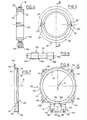
- Each half-shell 110 consists of a generally flat surface 111 in the form of a crown, to which a coaxial cylindrical jacket 112 is connected.
- the flat surface 111 is internally chamfered.
- each of the cylindrical liners 112 has, on its outer periphery, and at its free edge, opposite the flat surface 111, generally parallel tabs 113 on the planar surface 111, and provided with through orifices 114. Again, these are intended to receive any suitable locking device, such as threaded members for rigidly connecting the half-shells 110.
- each of the half-shells 110 is provided with a hollow body 115 communicating with the interior of the cylindrical jacket 112, so as to define, in the assembled position, a chamber capable of receiving a screw 150 cooperating with the crown 130. More specifically, the chamber is adapted to receive the screw 150 free to rotate, but immobilized in translation, in position adjacent to the crown, so that the thread provided on the periphery of the screw 150 meshes with a toothing 131 , such as a straight toothing, provided on the outer device of the toothed ring 130 received in the aforementioned housing.
- a toothing 131 such as a straight toothing
- a screw 150 which consists of a cylindrical annular body 151 smooth, provided over a part of its length, of the order of a third, with an external thread 152 At one of its ends, the screw has a head 153.
- the section presenting the thread 152 has an outside diameter greater than that of the rest of the smooth cylindrical rod 151.
- the aforementioned hollow bodies 115 provided on the half-shells 110 define on the one hand, a semi-cylindrical chamber 116 intended to receive the thread 152 , on the other hand, two semi-cylindrical recesses 117, of smaller radius, on either side of the chamber 116 and coaxial with it, to receive the smooth rod 151 of the screw 150.
- the axis R of the chamber 116 formed by the hollow body 115 connected to the outside of the cylindrical jacket 112 extends perpendicular to the axis S of the latter.
- the hollow body 115 is provided with holes 118, allowing the relative immobilization of two half-shells 110 to form the protective cage.
- the radial surfaces 119 and 120 on the one hand, 154, 155 on the other hand, provided respectively on the half-shells 110 (which delimit the radial surfaces of the chamber 116) and on the screw 150 (which delimits the radial surfaces of the thread 152) allow immobilization in translation of the screw 150 relative to the protective cage, when the thread 152 is introduced into the chamber 116.
- the protective cage being immobilized relative to one of the elements of each articulation, it is understood that any rotation of the screw 150 in engagement with the toothed crown 130, causes the latter to rotate about its own axis. , so as to cause a relative pivoting of the two elements of each joint.
- the ring gear 130 is integral in rotation with the housing 20 and the screw 150 is integral in translation of the support 50.
- the ring gear 130 While at the level of said adjustment assembly 100B associated with the mast 10 / housing 20 articulation, the ring gear 130 is integral in rotation with the housing 20 and the screw 150 is integral in translation with the mast 10.
- the teeth 131 provided on the ring gear 130 are more precisely provided on the outside of an annular rib 132 provided on the outer periphery of the ring 130, and whose width corresponds substantially half the thickness of this crown 130.
- the crown 130 has two radial grooves 133 diametrically opposite, in which are intended to penetrate an extreme portion of the planar edges 24, 24 'to 26, 26', of an appropriate width, of the aforementioned casing.
- the ring gear 130 is engaged in translation on the casing 20 and immobilized in rotation thereon by virtue of the abovementioned cooperation between the grooves 133 and the free edges of the casing.
- the width of the rib 132 corresponds to twice the height of the cylindrical jacket 112, and the outside radius of this rib 132, at most equal to the internal radius of the jacket 112, while the remaining thickness of the crown 130, on either side of the rib 132, at the surface referenced 135 in FIG. 4 equals the thickness of the planar wall 111, and has a radius of curvature substantially less than that of the internal cylindrical surface 121 of the crown 111.
- FIG. 8 shows a detailed view, on an enlarged scale, of the teeth 152 formed on the screw 150, and of the teeth 131 provided on the outer surface of the crown 130.
- the adjustment assembly 100B is then threaded onto the mast 10, and brought to bear against the upper surface of the sleeve 12, by gravity.
- the adjustment assembly 100B (and more precisely the half-shells 110) is immobilized in rotation relative to the bush 12 and to the mast 10 by virtue of the aforesaid lugs 101.
- the casing 20, provided with the adjustment assembly 100A on one end of the wings 23, 23 ′ and carrying the antenna support 50, thanks to the closure plugs 70 and the threaded rod 80, is then threaded onto the fixed mast 10.
- the casing 20 is immobilized in rotation relative to the toothed wheel 130 housed in the protective cage of the adjustment assembly 100B thanks to the flat edges 24, 24 'and 25, 25' engaged in the radial grooves 133.
- the ring gear 130 associated with the adjustment assembly 100A is immobilized in rotation relative to the casing 20 by virtue of the complementary planar edges engaged in the radial grooves 133 thereof.
- the immobilization in translation of this same ring 130 on the casing 20 is obtained by means of the threaded rod 80 and the shutters 70.
- the adjustment in elevation is carried out, by loosening the threaded rod 80, and by acting on the screw 150 associated with the adjustment assembly 100A, to drive the antenna support 50 in rotation around the axis PP of the housing 20.
- the antenna support 50 is locked in position by means of the threaded rod 80.
- the toothed crown 130 or the casing 20 is provided with a fixed mark, and one of the half-shells 110 forming a protective cage is provided with a graduated scale 122 (FIG. 1) to facilitate precise adjustment. .
- the separate plugs 70 could be eliminated and replaced by a structure integrated into the walls 53, 54, angles; such a structure could for example take the form of a cylindrical imprint of dimensions adapted to penetrate the chamber defined by the cooperation of the wings 23, 23 '.
Landscapes
- Support Of Aerials (AREA)
Applications Claiming Priority (2)
| Application Number | Priority Date | Filing Date | Title |
|---|---|---|---|
| FR8221308 | 1982-12-20 | ||
| FR8221308A FR2538173A1 (fr) | 1982-12-20 | 1982-12-20 | Dispositif d'orientation omnidirectionnelle d'une antenne |
Publications (3)
| Publication Number | Publication Date |
|---|---|
| EP0114543A2 EP0114543A2 (fr) | 1984-08-01 |
| EP0114543A3 EP0114543A3 (en) | 1984-08-22 |
| EP0114543B1 true EP0114543B1 (fr) | 1988-02-24 |
Family
ID=9280268
Family Applications (1)
| Application Number | Title | Priority Date | Filing Date |
|---|---|---|---|
| EP83402362A Expired EP0114543B1 (fr) | 1982-12-20 | 1983-12-06 | Dispositif d'orientation omnidirectionnelle d'une antenne |
Country Status (4)
| Country | Link |
|---|---|
| US (1) | US4612551A (enExample) |
| EP (1) | EP0114543B1 (enExample) |
| DE (1) | DE3375754D1 (enExample) |
| FR (1) | FR2538173A1 (enExample) |
Families Citing this family (9)
| Publication number | Priority date | Publication date | Assignee | Title |
|---|---|---|---|---|
| DE3605860C1 (de) * | 1986-02-24 | 1987-08-20 | Hirschmann Radiotechnik | Vorrichtung zur Befestigung einer Mikrowellenantenne mit in der Elevation einstellbarem Flaechenreflektor |
| EP0291268A3 (en) * | 1987-05-11 | 1989-10-18 | Varitrack Dbs Limited | Mountings for telecommunications dishes |
| GB2209095A (en) * | 1987-08-25 | 1989-04-26 | Varitrack D B S Limited | Method of mounting a dished telecommunications receiver |
| JPS6412702A (en) * | 1987-07-07 | 1989-01-17 | Toshiba Corp | Portable reception antenna system |
| US5103236A (en) * | 1989-12-20 | 1992-04-07 | Janiel Corporation | Antenna mount |
| DE9010737U1 (de) * | 1990-07-18 | 1991-01-10 | Scharf, Peter, 82538 Geretsried | Antennenmast für Wohnwagen oder Boote |
| US5517205A (en) * | 1993-03-31 | 1996-05-14 | Kvh Industries, Inc. | Two axis mount pointing apparatus |
| FI113584B (fi) * | 1999-01-20 | 2004-05-14 | Nokia Corp | Säätönivel asennon säätämiseksi ja lukitsemiseksi |
| US7142168B1 (en) | 2004-10-01 | 2006-11-28 | Patriot Antenna Systems, Inc. | Apparatus for mounting and adjusting a satellite antenna |
Family Cites Families (6)
| Publication number | Priority date | Publication date | Assignee | Title |
|---|---|---|---|---|
| US3146452A (en) * | 1953-06-10 | 1964-08-25 | Joseph K Rose | Remotely operated hand crank and gear drive for orientation of antennas on a mast |
| US3510877A (en) * | 1967-09-07 | 1970-05-05 | Int Standard Electric Corp | Antenna positioning device for following moving bodies |
| DE1956172A1 (de) * | 1969-11-07 | 1971-05-13 | Siemens Ag | Vorrichtung zur Befestigung einer Antennenanordnung |
| DE2246945A1 (de) * | 1972-09-25 | 1974-04-11 | Siemens Ag | Einrichtung zum schwenken einer richtfunkantenne in vertikaler und horizontaler richtung |
| SE7308903L (enExample) * | 1973-06-25 | 1974-12-27 | Moderna Butiksinredningar Ab | |
| US3951511A (en) * | 1973-12-19 | 1976-04-20 | Parsons J Howard | Astronomical telescope mount |
-
1982
- 1982-12-20 FR FR8221308A patent/FR2538173A1/fr active Granted
-
1983
- 1983-12-06 DE DE8383402362T patent/DE3375754D1/de not_active Expired
- 1983-12-06 EP EP83402362A patent/EP0114543B1/fr not_active Expired
- 1983-12-19 US US06/563,078 patent/US4612551A/en not_active Expired - Fee Related
Also Published As
| Publication number | Publication date |
|---|---|
| DE3375754D1 (en) | 1988-03-31 |
| FR2538173A1 (fr) | 1984-06-22 |
| EP0114543A3 (en) | 1984-08-22 |
| EP0114543A2 (fr) | 1984-08-01 |
| US4612551A (en) | 1986-09-16 |
| FR2538173B1 (enExample) | 1985-05-03 |
Similar Documents
| Publication | Publication Date | Title |
|---|---|---|
| FR2604132A1 (fr) | Dispositif de fixation pour lampe de vehicule automobile | |
| EP0427584A1 (fr) | Dispositif de maintien d'un organe tubulaire en particulier d'une colonne de direction de véhicule automobile | |
| EP0114543B1 (fr) | Dispositif d'orientation omnidirectionnelle d'une antenne | |
| EP0623485B1 (fr) | Articulation pour sièges de véhicules automobiles | |
| FR2525001A1 (fr) | Dispositif pour le reglage progressif des positions relatives de deux organes mutuellement deplacables | |
| EP0024976A1 (fr) | Dispositif de réglage de l'inclinaison relative de deux organes et notamment des deux parties d'un siège de véhicule automobile | |
| EP0610124B1 (fr) | Système d'assemblage de deux constituants d'une prothèse | |
| EP0281442A1 (fr) | Dispositif de réglage de la position angulaire d'un volant sur une colonne de direction de véhicule automobile et volant équipé d'un tel dispositif | |
| FR2559108A1 (fr) | Dispositif de reglage de l'orientation et de l'inclinaison d'un projecteur pour vehicules automobiles | |
| EP0035930A1 (fr) | Support d'antenne de réception d'émissions d'un satellite géostationnaire, et antenne comportant un tel support | |
| EP0233813B1 (fr) | Dispositif de réglage perfectionné de la position angulaire d'un organe sur un arbre, notamment d'un volant sur un arbre de direction | |
| EP0429336A1 (fr) | Bouchon de réservoir, en particulier bouchon de réservoir à carburant pour véhicule automobile | |
| EP0424247A1 (fr) | Dispositif de compression de ressorts | |
| EP0565422B1 (fr) | Dispositif de montage d'une partie de projecteur de véhicule automobile | |
| FR2871190A1 (fr) | Dispositif de support d'un arbre d'enroulement d'une installation de fermeture ou de protection solaire, et installation correspondante | |
| EP0877186B1 (fr) | Dispositif de raccordement d'éléments de tuyauterie | |
| FR2525536A1 (enExample) | ||
| EP0112205A1 (fr) | Support d'antenne de télécommunications par satellite géostationnaire et ensemble formé par un tel support et son antenne | |
| BE1012055A3 (fr) | Dispositif de fixation par ecrou. | |
| FR2772819A1 (fr) | Semelle de reglage d'une gache de serrure de vehicule automobile | |
| EP0307327A1 (fr) | Dispositif de liaison à vis entre deux pièces avec possibilité de réglage de l'écartement entre celles-ci | |
| FR2696492A1 (fr) | Serrure comprenant un stator destiné à être immobilisé dans un support. | |
| FR2696136A1 (fr) | Accoudoir pivotant de véhicule automobile. | |
| FR2514570A1 (fr) | Support d'antenne destinee a capter des emissions de television provenant d'un satellite geostationnaire et ensemble forme par un tel support et son antenne | |
| EP0242486B1 (fr) | Dispositif de fixation |
Legal Events
| Date | Code | Title | Description |
|---|---|---|---|
| PUAI | Public reference made under article 153(3) epc to a published international application that has entered the european phase |
Free format text: ORIGINAL CODE: 0009012 |
|
| PUAL | Search report despatched |
Free format text: ORIGINAL CODE: 0009013 |
|
| AK | Designated contracting states |
Designated state(s): DE GB IT |
|
| AK | Designated contracting states |
Designated state(s): DE GB IT |
|
| 17P | Request for examination filed |
Effective date: 19841227 |
|
| 17Q | First examination report despatched |
Effective date: 19860905 |
|
| GRAA | (expected) grant |
Free format text: ORIGINAL CODE: 0009210 |
|
| AK | Designated contracting states |
Kind code of ref document: B1 Designated state(s): DE GB IT |
|
| REF | Corresponds to: |
Ref document number: 3375754 Country of ref document: DE Date of ref document: 19880331 |
|
| GBT | Gb: translation of ep patent filed (gb section 77(6)(a)/1977) | ||
| ITF | It: translation for a ep patent filed | ||
| PLBE | No opposition filed within time limit |
Free format text: ORIGINAL CODE: 0009261 |
|
| STAA | Information on the status of an ep patent application or granted ep patent |
Free format text: STATUS: NO OPPOSITION FILED WITHIN TIME LIMIT |
|
| 26N | No opposition filed | ||
| PGFP | Annual fee paid to national office [announced via postgrant information from national office to epo] |
Ref country code: DE Payment date: 19891222 Year of fee payment: 7 |
|
| ITTA | It: last paid annual fee | ||
| PGFP | Annual fee paid to national office [announced via postgrant information from national office to epo] |
Ref country code: GB Payment date: 19891231 Year of fee payment: 7 |
|
| PG25 | Lapsed in a contracting state [announced via postgrant information from national office to epo] |
Ref country code: GB Effective date: 19901206 |
|
| GBPC | Gb: european patent ceased through non-payment of renewal fee | ||
| PG25 | Lapsed in a contracting state [announced via postgrant information from national office to epo] |
Ref country code: DE Effective date: 19910903 |