EP0113726B1 - A valve - Google Patents
A valve Download PDFInfo
- Publication number
- EP0113726B1 EP0113726B1 EP83900642A EP83900642A EP0113726B1 EP 0113726 B1 EP0113726 B1 EP 0113726B1 EP 83900642 A EP83900642 A EP 83900642A EP 83900642 A EP83900642 A EP 83900642A EP 0113726 B1 EP0113726 B1 EP 0113726B1
- Authority
- EP
- European Patent Office
- Prior art keywords
- diaphragm
- engine
- crankcase
- valve
- aperture
- Prior art date
- Legal status (The legal status is an assumption and is not a legal conclusion. Google has not performed a legal analysis and makes no representation as to the accuracy of the status listed.)
- Expired
Links
- 239000007789 gas Substances 0.000 claims description 18
- 230000006698 induction Effects 0.000 claims description 9
- 238000002485 combustion reaction Methods 0.000 claims description 6
- 238000005096 rolling process Methods 0.000 abstract description 5
- 239000011324 bead Substances 0.000 description 3
- 238000010586 diagram Methods 0.000 description 3
- 230000015572 biosynthetic process Effects 0.000 description 2
- 238000005755 formation reaction Methods 0.000 description 2
- 230000006835 compression Effects 0.000 description 1
- 238000007906 compression Methods 0.000 description 1
- 238000004519 manufacturing process Methods 0.000 description 1
- 230000000750 progressive effect Effects 0.000 description 1
- 238000007789 sealing Methods 0.000 description 1
Images

Classifications
-
- F—MECHANICAL ENGINEERING; LIGHTING; HEATING; WEAPONS; BLASTING
- F16—ENGINEERING ELEMENTS AND UNITS; GENERAL MEASURES FOR PRODUCING AND MAINTAINING EFFECTIVE FUNCTIONING OF MACHINES OR INSTALLATIONS; THERMAL INSULATION IN GENERAL
- F16K—VALVES; TAPS; COCKS; ACTUATING-FLOATS; DEVICES FOR VENTING OR AERATING
- F16K7/00—Diaphragm valves or cut-off apparatus, e.g. with a member deformed, but not moved bodily, to close the passage ; Pinch valves
- F16K7/18—Diaphragm valves or cut-off apparatus, e.g. with a member deformed, but not moved bodily, to close the passage ; Pinch valves with diaphragm secured at one side only, e.g. to be laid on the seat by rolling action
-
- F—MECHANICAL ENGINEERING; LIGHTING; HEATING; WEAPONS; BLASTING
- F01—MACHINES OR ENGINES IN GENERAL; ENGINE PLANTS IN GENERAL; STEAM ENGINES
- F01M—LUBRICATING OF MACHINES OR ENGINES IN GENERAL; LUBRICATING INTERNAL COMBUSTION ENGINES; CRANKCASE VENTILATING
- F01M13/00—Crankcase ventilating or breathing
- F01M13/02—Crankcase ventilating or breathing by means of additional source of positive or negative pressure
- F01M13/021—Crankcase ventilating or breathing by means of additional source of positive or negative pressure of negative pressure
- F01M13/022—Crankcase ventilating or breathing by means of additional source of positive or negative pressure of negative pressure using engine inlet suction
- F01M13/023—Control valves in suction conduit
Definitions
- This invention relates to an internal combustion engine having a valve to vent gases from the crankcase to the induction manifold when the pressure in the crankcase exceeds atmospheric pressure.
- An engine crankcase breather valve should vent gases from the crankcase to the induction manifold while at the same time preventing suction in the manifold from reducing the pressure in the crankcase. A failure to vent gases may result in the expulsion of oil from the crankcase while a reduction in the crankcase pressure may draw dirt into the crankcase.
- An object of the present invention is to provide an improved crankcase breather valve to avoid the aforesaid difficulties.
- an internal combustion engine is provided with a crankcase breather valve comprising a housing having a gas inlet connected to the crankcase, a gas outlet connected to the induction manifold, inner and outer co-axial members with the inner member movable against spring means in reponse to gas pressure, an annular flexible diaphragm connected between said pair of members and having a portion of U-section that moves with said inner member and an aperture in said outer member with which the diaphragm co-operates to close said aoperture in response to movement of said inner member said inner member being located in relation to the gas in-let so as to be reponsive to gas inlet pressures, and the outer member being located within the housing and being formed with said aperture therein so as to communicate between said gas inlet and outlet when uncovered by the diaphragm.
- Valves utilizing a rolling diaphragm closure member are known per se e.g. from US--A-3 766 933. This valve is used to control or limit the vacuum applied to equipment in paper making plant.
- crankcase breather valve illustrated in Figures 1 and 2 has a two part housing comprising a lower portion 1 with a cylindrical inlet duct 2 projecting downwards from its base 3, and an upper cover portion 4.
- a semi-cylindrical formation 5 projects from the side of each housing portion and these formations co-operate to form an outlet duct 6.
- An annular rolling diaphragm 7 is provided within the valve housing between an outer cylindrical support member 8 and an inner guide member 9.
- a bead 10 at the outer edge of the diaphragm is held in place in a gallery 11 in the upper end of the support member 8.
- An annular wall 12 on the underside of the over portion 4 engages the gallery 11 to clamp the bead 10 in place and to locate the support member 8 with its lower end in engagement with a groove 13 in the base 3 of the lower housing portion.
- the guide member has downwardly projecting guide fins 17 that engage within the inlet duct 2 to guide vertical movement of the disc-shaped portion 16.
- a compression spring 18 between the housing cover portion 4 and the disc-shaped portion 16 serves to urge the latter into engagement with an annular abutment 19 formed in the base of the lower housing portion 1 around the inlet duct 2.
- a series of apertures 20 are formed in the wall of the cylindrical support member 8 and are covered by the diaphragm 7 when the guide member 9 engages the abutment 19.
- upwards movement of the diaphragm 7 guided by the guide member at its inner edge causes the diaphragm to roll' back on itself and to uncover the apertures 20, thereby allowing communication between the inlet duct 2 and outlet duct 6.
- a hole 21 in the cover portion 4 vents the space above the guide member 9 and diaphragm 7 to atmosphere.
- the strength of the spring 18 determines the pressure at which the valve opens.
- each aperture 20 is triangular in shape and is orientated with a point lowermost.
- the apertures 20 could also be circular in shape.
- FIG 8 shows an internal combustion engine fitted with a crankshaft breather valve 30 according to Figures 1 to 4.
- the inlet duct 2 of the valve 30 is connected to the crankcase 31 and the outlet duct 6 is connected to the induction manifold 32 of the engine.
- the valve is then responsive to crankcase pressures above atmospheric and opens at a pressure determined by the characteristics of the spring 18 and area of the guide member 9 and the diaphragm 7 to vent crankcase gases through the outlet duct 6 to the induction manifold.
- any suction production in the induction manifold will produce a sealing action of the diaphragm and will not pass through the inlet duct 2 to the crankcase where it could draw dirt in through the crankcase seals.
- crankcase breather valve for use according to the invention is illustrated in Figures 5 to 7 in which the inlet and outlet ducts are arranged coaxially rather than at right angles to one another.
- the valve housing again comprises two co-operating portions 22, 23.
- the lower portion 22 has a downwardly projecting inlet duct 2 in its base 3 as in the previous embodiment.
- the upper cover portion 23 has an upwardly projecting outlet duct 24 in its top wall 25.
- a disc-shaped intermediate member 26 is clamped at its periphery between the two housing portions 22, 23.
- a guide member 9, a cylindrical support member 8, a diaphragm 7 and a spring 18, all exactly the same as in the previous embodiment, are provided within the valve housing and located by a groove 13 in the base of the lower housing portion 22 and an annular wall 27 on the underside of the intermediate member 26 that corresponds to the wall 12 of the previous embodiment.
- the annular space between the support member 8 and lower housing portion 22 communicates with the outlet duct 24 via apertures 28 formed in the intermediate member 26.
- a bore 29 vents to atmosphere the space between the guide member 9 and diaphragm 7 and the intermediate member 26.
- This valve operates in exactly the same manner as the previous embodiment but when the valve is open, the inlet duct 2 communicates with the outlet duct 24 through the apertures 20 and 28.
Landscapes
- Engineering & Computer Science (AREA)
- General Engineering & Computer Science (AREA)
- Mechanical Engineering (AREA)
- Lubrication Details And Ventilation Of Internal Combustion Engines (AREA)
- Safety Valves (AREA)
- Control Of Fluid Pressure (AREA)
Abstract
Description
- This invention relates to an internal combustion engine having a valve to vent gases from the crankcase to the induction manifold when the pressure in the crankcase exceeds atmospheric pressure.
- An engine crankcase breather valve should vent gases from the crankcase to the induction manifold while at the same time preventing suction in the manifold from reducing the pressure in the crankcase. A failure to vent gases may result in the expulsion of oil from the crankcase while a reduction in the crankcase pressure may draw dirt into the crankcase. An object of the present invention is to provide an improved crankcase breather valve to avoid the aforesaid difficulties.
- According to the invention an internal combustion engine is provided with a crankcase breather valve comprising a housing having a gas inlet connected to the crankcase, a gas outlet connected to the induction manifold, inner and outer co-axial members with the inner member movable against spring means in reponse to gas pressure, an annular flexible diaphragm connected between said pair of members and having a portion of U-section that moves with said inner member and an aperture in said outer member with which the diaphragm co-operates to close said aoperture in response to movement of said inner member said inner member being located in relation to the gas in-let so as to be reponsive to gas inlet pressures, and the outer member being located within the housing and being formed with said aperture therein so as to communicate between said gas inlet and outlet when uncovered by the diaphragm.
- An advantage of this valve is that it operates substantially independently of the pressure of the outlet side of the outlet opening. Suction at the outlet opening will simply cause it to be more firmly sealed by the diaphragm.
- Valves utilizing a rolling diaphragm closure member are known per se e.g. from US--A-3 766 933. This valve is used to control or limit the vacuum applied to equipment in paper making plant.
- The invention will be described by way of example with reference to the accompanying drawings in which:
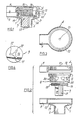
- Figure 1 is an axial section through one embodiment of an engine crankcase breather valve for use in an internal combustion engine according to the invention.
- Figure 2 is an exploded diagram of the valve of Figure 1 without the rolling diaphragm.
- Figure 3 is an underside plan view-of the upper half of the valve housing of Figures 1 and 2.
- Figure 4 is an underside plan view of the valve member of Figures 1 and 2.
- Figure 5 is an axial section through another embodiment of an engine crankcase breather valve for use in an internal combustion engine according to the invention.
- Figure 6 is an exploded diagram of parts of the valve of Figure 5 without the rolling diaphragm.
- Figure 7 is an underside plan view of the intermediate part of the valve of Figure 5, and
- Figure 8 is a schematic diagram of an-internal combusion engine having a crankcase breather valve according to the invention.
- The crankcase breather valve illustrated in Figures 1 and 2 has a two part housing comprising a lower portion 1 with a
cylindrical inlet duct 2 projecting downwards from itsbase 3, and an upper cover portion 4. Asemi-cylindrical formation 5 projects from the side of each housing portion and these formations co-operate to form an outlet duct 6. - An
annular rolling diaphragm 7 is provided within the valve housing between an outercylindrical support member 8 and aninner guide member 9. - A
bead 10 at the outer edge of the diaphragm is held in place in a gallery 11 in the upper end of thesupport member 8. Anannular wall 12 on the underside of the over portion 4 engages the gallery 11 to clamp thebead 10 in place and to locate thesupport member 8 with its lower end in engagement with agroove 13 in thebase 3 of the lower housing portion. - A
bead 14 at the inner edge of the diaphragm engages agroove 15 in the outer periphery of a disc-shaped portion 16 of theguide_member 9. The guide member has downwardly projectingguide fins 17 that engage within theinlet duct 2 to guide vertical movement of the disc-shapedportion 16. Acompression spring 18 between the housing cover portion 4 and the disc-shaped portion 16 serves to urge the latter into engagement with anannular abutment 19 formed in the base of the lower housing portion 1 around theinlet duct 2. - A series of
apertures 20 are formed in the wall of thecylindrical support member 8 and are covered by thediaphragm 7 when theguide member 9 engages theabutment 19. However, upwards movement of thediaphragm 7 guided by the guide member at its inner edge causes the diaphragm to roll' back on itself and to uncover theapertures 20, thereby allowing communication between theinlet duct 2 and outlet duct 6. - A
hole 21 in the cover portion 4 vents the space above theguide member 9 anddiaphragm 7 to atmosphere. The strength of thespring 18 determines the pressure at which the valve opens. - An important characteristic of this valve is that, when the
diaphragm 7 closes theapertures 20, any fall in pressure in the outlet duct 6 below atmospheric will cause thediaphragm 7 to seal theapertures 20 more firmly. Theapertures 20 are shaped so that they are of the reduced width towards their bottoms, thereby giving a progressive initial opening of the apertures by the diaphragm and a longer initial movement of theguide member 9 which is thus more easily damped by thespring 18 and air between the diaphragm and the cover portion 4. As illustrated in Figure 2, eachaperture 20 is triangular in shape and is orientated with a point lowermost. However, theapertures 20 could also be circular in shape. - Figure 8 shows an internal combustion engine fitted with a
crankshaft breather valve 30 according to Figures 1 to 4. Theinlet duct 2 of thevalve 30 is connected to thecrankcase 31 and the outlet duct 6 is connected to theinduction manifold 32 of the engine. The valve is then responsive to crankcase pressures above atmospheric and opens at a pressure determined by the characteristics of thespring 18 and area of theguide member 9 and thediaphragm 7 to vent crankcase gases through the outlet duct 6 to the induction manifold. On the other hand, any suction production in the induction manifold will produce a sealing action of the diaphragm and will not pass through theinlet duct 2 to the crankcase where it could draw dirt in through the crankcase seals. - An alternative form of crankcase breather valve for use according to the invention is illustrated in Figures 5 to 7 in which the inlet and outlet ducts are arranged coaxially rather than at right angles to one another. The valve housing again comprises two
co-operating portions lower portion 22 has a downwardly projectinginlet duct 2 in itsbase 3 as in the previous embodiment. Theupper cover portion 23 has an upwardly projectingoutlet duct 24 in itstop wall 25. A disc-shapedintermediate member 26 is clamped at its periphery between the twohousing portions guide member 9, acylindrical support member 8, adiaphragm 7 and aspring 18, all exactly the same as in the previous embodiment, are provided within the valve housing and located by agroove 13 in the base of thelower housing portion 22 and anannular wall 27 on the underside of theintermediate member 26 that corresponds to thewall 12 of the previous embodiment. The annular space between thesupport member 8 andlower housing portion 22 communicates with theoutlet duct 24 viaapertures 28 formed in theintermediate member 26. A bore 29 vents to atmosphere the space between theguide member 9 anddiaphragm 7 and theintermediate member 26. - This valve operates in exactly the same manner as the previous embodiment but when the valve is open, the
inlet duct 2 communicates with theoutlet duct 24 through theapertures
Claims (7)
Applications Claiming Priority (2)
| Application Number | Priority Date | Filing Date | Title |
|---|---|---|---|
| GB08204682A GB2115109B (en) | 1982-02-17 | 1982-02-17 | Vent valve |
| GB8204682 | 1982-02-17 |
Publications (2)
| Publication Number | Publication Date |
|---|---|
| EP0113726A1 EP0113726A1 (en) | 1984-07-25 |
| EP0113726B1 true EP0113726B1 (en) | 1986-04-09 |
Family
ID=10528409
Family Applications (1)
| Application Number | Title | Priority Date | Filing Date |
|---|---|---|---|
| EP83900642A Expired EP0113726B1 (en) | 1982-02-17 | 1983-02-01 | A valve |
Country Status (10)
| Country | Link |
|---|---|
| US (1) | US4502452A (en) |
| EP (1) | EP0113726B1 (en) |
| JP (1) | JPS59500922A (en) |
| CA (1) | CA1203731A (en) |
| DE (1) | DE3362860D1 (en) |
| ES (1) | ES519825A0 (en) |
| GB (1) | GB2115109B (en) |
| PL (1) | PL240606A1 (en) |
| WO (1) | WO1983002987A1 (en) |
| ZA (1) | ZA83725B (en) |
Cited By (1)
| Publication number | Priority date | Publication date | Assignee | Title |
|---|---|---|---|---|
| DE29605425U1 (en) * | 1996-03-23 | 1996-06-13 | Ing. Walter Hengst GmbH & Co KG, 48147 Münster | Drain valve for oil separators |
Families Citing this family (7)
| Publication number | Priority date | Publication date | Assignee | Title |
|---|---|---|---|---|
| DE3411625A1 (en) * | 1983-05-02 | 1984-11-08 | Thoratec Laboratories Corp., Berkeley, Calif. | PRESSURE REGULATOR |
| GR862472B (en) * | 1986-09-30 | 1986-10-09 | Elliniko Institouto Paster | Determination of antibodies specific of hsv-1 herpes or hsv-2 in human serum with the elisa technic using the specific antigen of hsv-1 or hsv-2 type in semi - clean form |
| DE19507202C2 (en) * | 1994-03-28 | 1998-07-16 | Knecht Filterwerke Gmbh | Vent valve |
| DE102006041213B4 (en) * | 2006-09-02 | 2017-06-29 | Mahle International Gmbh | Device for crank chamber ventilation |
| DE102007010536A1 (en) * | 2007-03-05 | 2008-09-11 | Continental Automotive Gmbh | Valve |
| JP5955525B2 (en) * | 2011-10-07 | 2016-07-20 | 愛三工業株式会社 | Flow control valve |
| US10724462B2 (en) * | 2012-04-20 | 2020-07-28 | General Electric Company | System and method for a compressor |
Family Cites Families (11)
| Publication number | Priority date | Publication date | Assignee | Title |
|---|---|---|---|---|
| US3144011A (en) * | 1961-11-01 | 1964-08-11 | Union Carbide Corp | Method and apparatus for providing closed ventilation circuit for automotive crankcases |
| US3620197A (en) * | 1970-01-20 | 1971-11-16 | Caterpillar Tractor Co | Crankcase ventilating means for submerged engine operation |
| US3766933A (en) * | 1970-07-27 | 1973-10-23 | Broughton Corp | Rolling diaphragm vacuum control |
| US3662724A (en) * | 1971-01-13 | 1972-05-16 | Chrysler Corp | Crankcase ventilation |
| US3678910A (en) * | 1971-03-31 | 1972-07-25 | Ford Motor Co | Control valve for positive crankcase ventilation system |
| GB1449258A (en) * | 1973-12-11 | 1976-09-15 | Berg L G | Flow control device |
| FR2308850A1 (en) * | 1975-04-23 | 1976-11-19 | Madec | Variable flow gas tap - has valve member on control rod moving valve strip over apertured diaphragm between inlet and outlet chambers |
| US4125127A (en) * | 1977-05-12 | 1978-11-14 | The Garrett Corporation | Piston type fluid pressure valve |
| DE2753335C2 (en) * | 1977-11-30 | 1983-05-19 | Klöckner-Humboldt-Deutz AG, 5000 Köln | Crankcase ventilation valve |
| DE3032243C2 (en) * | 1980-08-27 | 1983-05-05 | Filterwerk Mann & Hummel Gmbh, 7140 Ludwigsburg | Pressure control valve for installation in a vent line of an internal combustion engine |
| US4390036A (en) * | 1981-04-06 | 1983-06-28 | Bellofram Corporation | Rolling diaphragm vacuum control |
-
1982
- 1982-02-17 GB GB08204682A patent/GB2115109B/en not_active Expired
-
1983
- 1983-02-01 US US06/548,890 patent/US4502452A/en not_active Expired - Fee Related
- 1983-02-01 DE DE8383900642T patent/DE3362860D1/en not_active Expired
- 1983-02-01 EP EP83900642A patent/EP0113726B1/en not_active Expired
- 1983-02-01 JP JP58500743A patent/JPS59500922A/en active Pending
- 1983-02-01 WO PCT/GB1983/000023 patent/WO1983002987A1/en not_active Ceased
- 1983-02-03 ZA ZA83725A patent/ZA83725B/en unknown
- 1983-02-16 PL PL24060683A patent/PL240606A1/en unknown
- 1983-02-16 CA CA000421710A patent/CA1203731A/en not_active Expired
- 1983-02-16 ES ES519825A patent/ES519825A0/en active Granted
Cited By (1)
| Publication number | Priority date | Publication date | Assignee | Title |
|---|---|---|---|---|
| DE29605425U1 (en) * | 1996-03-23 | 1996-06-13 | Ing. Walter Hengst GmbH & Co KG, 48147 Münster | Drain valve for oil separators |
Also Published As
| Publication number | Publication date |
|---|---|
| GB2115109A (en) | 1983-09-01 |
| EP0113726A1 (en) | 1984-07-25 |
| JPS59500922A (en) | 1984-05-24 |
| CA1203731A (en) | 1986-04-29 |
| PL240606A1 (en) | 1983-12-05 |
| GB2115109B (en) | 1985-04-17 |
| US4502452A (en) | 1985-03-05 |
| WO1983002987A1 (en) | 1983-09-01 |
| ES8403205A1 (en) | 1984-03-01 |
| ES519825A0 (en) | 1984-03-01 |
| DE3362860D1 (en) | 1986-05-15 |
| ZA83725B (en) | 1983-10-26 |
Similar Documents
| Publication | Publication Date | Title |
|---|---|---|
| US5507318A (en) | Umbrella check valves | |
| JPS5851394Y2 (en) | Tank internal pressure control device | |
| EP0100657A1 (en) | Air admittance valve | |
| US5226398A (en) | Regulated flow canister purge system | |
| US4502452A (en) | Valve | |
| KR100491400B1 (en) | Valve for sucking up gases from an internal combustion engine crankcase | |
| US4580543A (en) | Ventilator for internal combustion engine | |
| JP2004144085A (en) | Pressure regulating valve | |
| US3996955A (en) | Vacuum supply valve | |
| US3263660A (en) | Pressure regulator | |
| US3934413A (en) | Air flow control unit for engine secondary air supply | |
| US4166476A (en) | Vacuum cut-off valve | |
| US4217870A (en) | Venting valve for crankcases of reciprocable piston internal combustion engines | |
| GB1392977A (en) | Device for ventilating a fuel tank for an internal cobustion egnine | |
| US3108581A (en) | Crankcase pressure controller | |
| US4198028A (en) | Deceleration valve | |
| US4364301A (en) | Vacuum actuator | |
| US3144044A (en) | Apparatus for providing closed ventilation of automotive crankcases | |
| US3804109A (en) | Vacuum bias switch | |
| US3722852A (en) | Relief valve | |
| US3620197A (en) | Crankcase ventilating means for submerged engine operation | |
| GB1495870A (en) | Crankcase breathers for internal combustion engines | |
| US4178953A (en) | Fail safe bypass valve | |
| US2316649A (en) | Relief valve | |
| US3380441A (en) | Crankcase ventilation flow regulator valve |
Legal Events
| Date | Code | Title | Description |
|---|---|---|---|
| PUAI | Public reference made under article 153(3) epc to a published international application that has entered the european phase |
Free format text: ORIGINAL CODE: 0009012 |
|
| 17P | Request for examination filed |
Effective date: 19840125 |
|
| AK | Designated contracting states |
Designated state(s): DE FR GB |
|
| GRAA | (expected) grant |
Free format text: ORIGINAL CODE: 0009210 |
|
| AK | Designated contracting states |
Kind code of ref document: B1 Designated state(s): DE FR GB |
|
| REF | Corresponds to: |
Ref document number: 3362860 Country of ref document: DE Date of ref document: 19860515 |
|
| ET | Fr: translation filed | ||
| PLBE | No opposition filed within time limit |
Free format text: ORIGINAL CODE: 0009261 |
|
| STAA | Information on the status of an ep patent application or granted ep patent |
Free format text: STATUS: NO OPPOSITION FILED WITHIN TIME LIMIT |
|
| 26N | No opposition filed | ||
| PG25 | Lapsed in a contracting state [announced via postgrant information from national office to epo] |
Ref country code: FR Free format text: LAPSE BECAUSE OF NON-PAYMENT OF DUE FEES Effective date: 19881028 |
|
| PG25 | Lapsed in a contracting state [announced via postgrant information from national office to epo] |
Ref country code: DE Effective date: 19881101 |
|
| REG | Reference to a national code |
Ref country code: FR Ref legal event code: ST |
|
| PGFP | Annual fee paid to national office [announced via postgrant information from national office to epo] |
Ref country code: GB Payment date: 19990126 Year of fee payment: 17 |
|
| PG25 | Lapsed in a contracting state [announced via postgrant information from national office to epo] |
Ref country code: GB Free format text: LAPSE BECAUSE OF NON-PAYMENT OF DUE FEES Effective date: 20000201 |
|
| GBPC | Gb: european patent ceased through non-payment of renewal fee |
Effective date: 20000201 |