EP0113145A1 - Connection device with a plurality of degrees of freedom - Google Patents
Connection device with a plurality of degrees of freedom Download PDFInfo
- Publication number
- EP0113145A1 EP0113145A1 EP83201759A EP83201759A EP0113145A1 EP 0113145 A1 EP0113145 A1 EP 0113145A1 EP 83201759 A EP83201759 A EP 83201759A EP 83201759 A EP83201759 A EP 83201759A EP 0113145 A1 EP0113145 A1 EP 0113145A1
- Authority
- EP
- European Patent Office
- Prior art keywords
- flexible
- cylinders
- flexible cylinders
- movable member
- variable capacity
- Prior art date
- Legal status (The legal status is an assumption and is not a legal conclusion. Google has not performed a legal analysis and makes no representation as to the accuracy of the status listed.)
- Granted
Links
Images


Classifications
-
- F—MECHANICAL ENGINEERING; LIGHTING; HEATING; WEAPONS; BLASTING
- F15—FLUID-PRESSURE ACTUATORS; HYDRAULICS OR PNEUMATICS IN GENERAL
- F15B—SYSTEMS ACTING BY MEANS OF FLUIDS IN GENERAL; FLUID-PRESSURE ACTUATORS, e.g. SERVOMOTORS; DETAILS OF FLUID-PRESSURE SYSTEMS, NOT OTHERWISE PROVIDED FOR
- F15B7/00—Systems in which the movement produced is definitely related to the output of a volumetric pump; Telemotors
- F15B7/003—Systems in which the movement produced is definitely related to the output of a volumetric pump; Telemotors with multiple outputs
-
- B—PERFORMING OPERATIONS; TRANSPORTING
- B25—HAND TOOLS; PORTABLE POWER-DRIVEN TOOLS; MANIPULATORS
- B25J—MANIPULATORS; CHAMBERS PROVIDED WITH MANIPULATION DEVICES
- B25J17/00—Joints
- B25J17/02—Wrist joints
- B25J17/0208—Compliance devices
-
- B—PERFORMING OPERATIONS; TRANSPORTING
- B25—HAND TOOLS; PORTABLE POWER-DRIVEN TOOLS; MANIPULATORS
- B25J—MANIPULATORS; CHAMBERS PROVIDED WITH MANIPULATION DEVICES
- B25J17/00—Joints
- B25J17/02—Wrist joints
- B25J17/0283—Three-dimensional joints
-
- B—PERFORMING OPERATIONS; TRANSPORTING
- B25—HAND TOOLS; PORTABLE POWER-DRIVEN TOOLS; MANIPULATORS
- B25J—MANIPULATORS; CHAMBERS PROVIDED WITH MANIPULATION DEVICES
- B25J18/00—Arms
- B25J18/06—Arms flexible
-
- B—PERFORMING OPERATIONS; TRANSPORTING
- B25—HAND TOOLS; PORTABLE POWER-DRIVEN TOOLS; MANIPULATORS
- B25J—MANIPULATORS; CHAMBERS PROVIDED WITH MANIPULATION DEVICES
- B25J9/00—Programme-controlled manipulators
- B25J9/06—Programme-controlled manipulators characterised by multi-articulated arms
-
- B—PERFORMING OPERATIONS; TRANSPORTING
- B25—HAND TOOLS; PORTABLE POWER-DRIVEN TOOLS; MANIPULATORS
- B25J—MANIPULATORS; CHAMBERS PROVIDED WITH MANIPULATION DEVICES
- B25J9/00—Programme-controlled manipulators
- B25J9/10—Programme-controlled manipulators characterised by positioning means for manipulator elements
- B25J9/14—Programme-controlled manipulators characterised by positioning means for manipulator elements fluid
- B25J9/142—Programme-controlled manipulators characterised by positioning means for manipulator elements fluid comprising inflatable bodies
-
- F—MECHANICAL ENGINEERING; LIGHTING; HEATING; WEAPONS; BLASTING
- F15—FLUID-PRESSURE ACTUATORS; HYDRAULICS OR PNEUMATICS IN GENERAL
- F15B—SYSTEMS ACTING BY MEANS OF FLUIDS IN GENERAL; FLUID-PRESSURE ACTUATORS, e.g. SERVOMOTORS; DETAILS OF FLUID-PRESSURE SYSTEMS, NOT OTHERWISE PROVIDED FOR
- F15B15/00—Fluid-actuated devices for displacing a member from one position to another; Gearing associated therewith
- F15B15/08—Characterised by the construction of the motor unit
- F15B15/10—Characterised by the construction of the motor unit the motor being of diaphragm type
- F15B15/103—Characterised by the construction of the motor unit the motor being of diaphragm type using inflatable bodies that contract when fluid pressure is applied, e.g. pneumatic artificial muscles or McKibben-type actuators
-
- F—MECHANICAL ENGINEERING; LIGHTING; HEATING; WEAPONS; BLASTING
- F15—FLUID-PRESSURE ACTUATORS; HYDRAULICS OR PNEUMATICS IN GENERAL
- F15B—SYSTEMS ACTING BY MEANS OF FLUIDS IN GENERAL; FLUID-PRESSURE ACTUATORS, e.g. SERVOMOTORS; DETAILS OF FLUID-PRESSURE SYSTEMS, NOT OTHERWISE PROVIDED FOR
- F15B7/00—Systems in which the movement produced is definitely related to the output of a volumetric pump; Telemotors
- F15B7/001—With multiple inputs, e.g. for dual control
-
- F—MECHANICAL ENGINEERING; LIGHTING; HEATING; WEAPONS; BLASTING
- F15—FLUID-PRESSURE ACTUATORS; HYDRAULICS OR PNEUMATICS IN GENERAL
- F15B—SYSTEMS ACTING BY MEANS OF FLUIDS IN GENERAL; FLUID-PRESSURE ACTUATORS, e.g. SERVOMOTORS; DETAILS OF FLUID-PRESSURE SYSTEMS, NOT OTHERWISE PROVIDED FOR
- F15B7/00—Systems in which the movement produced is definitely related to the output of a volumetric pump; Telemotors
- F15B7/06—Details
- F15B7/08—Input units; Master units
Landscapes
- Engineering & Computer Science (AREA)
- Mechanical Engineering (AREA)
- Robotics (AREA)
- Physics & Mathematics (AREA)
- Fluid Mechanics (AREA)
- General Engineering & Computer Science (AREA)
- Chemical & Material Sciences (AREA)
- Analytical Chemistry (AREA)
- Manipulator (AREA)
- Actuator (AREA)
Abstract
L'invention concerne un dispositif mobile de liaison à plusieurs degrés de liberté entre un élément porteur (bras manipulateur ou autre) et un élément porté (outil, et en particulier outil de préhension. Le dispositif comprend une membrure-support (1) adaptée pour être fixée sur l'élément porteur, une membrure mobile (2) sur laquelle est fixé l'élément porté, une pluralité de vérins souples (5, 6, 7, 7', 8) agencés entre la membrure-support (1) et la membrure mobile (2) de façon à maintenir cette dernière par rapport à cette première dans une position relative fonction des états de déformation desdits vérins souples, et des moyens (13) de commande à distance des vérins souples, comprenant un réservoir de capacité variable associé à chaque vérin et formant avec celui-ci un circuit de fluide fermé. L'invention est applicable en robotique pour permettre de mouvoir un organe avec une puissance élevée et une bonne précision.The invention relates to a mobile device for connecting with several degrees of freedom between a support element (manipulator arm or the like) and a supported element (tool, and in particular gripping tool. The device comprises a support frame (1) suitable for be fixed on the supporting element, a movable member (2) on which the carried element is fixed, a plurality of flexible cylinders (5, 6, 7, 7 ', 8) arranged between the supporting member (1) and the movable member (2) so as to maintain the latter relative to this first in a relative position depending on the states of deformation of said flexible cylinders, and means (13) for remote control of the flexible cylinders, comprising a variable capacity tank associated with each cylinder and forming with it a closed fluid circuit The invention is applicable in robotics to allow movement of an organ with high power and good precision.
Description
L'invention concerne un dispositif mobile de liaison entre un élément porteur et un élément porté. Un tel dispositif permet de faire subir à l'élément porté des déplacements suivant plusieurs degrés de liberté par rapport à l'élément porteur.The invention relates to a mobile connection device between a carrier element and a carried element. Such a device makes it possible to subject the worn element to displacements according to several degrees of freedom relative to the carrying element.
Dans l'état actuel de la technique, la robotique utilise différents types de bras manipulateurs (hydrauliques, pneumatiques, électriques) constituant l'élément porteur, l'élément porté étant constitué par un outil, généralement σuti1 de préhension. La puissance du bras se trouve difficilement compatible avec la rapidité et surtout avec la précision de ses déplacements : les bras manipulateurs à câbles ou à rubans ont une bonne précision mais leur puissance est limitée tandis que les bras à action hydraulique sont puissants mais manquent souvent de précision. On a résolu partiellement ce problème en dotant le bras-manipulateur d'un organe de liaison souple, par exemple poignet de Nevins, apte à se déformer sous une contrainte dont il donne la grandeur et la direction. Il faut également que le bras puisse effectuer des déplacements de faible amplitude avec une grande précision en vue de réaliser l'assemblage souhaité. On a également envisagé la construction de bras dotés de poignets effectuant des déplacements de faible amplitude avec précision, mais ceux-ci nécessitent un grand nombre de moteurs munis de réducteurs lourds et encombrants qui réduisent d'autant la puissance du bras.In the current state of the art, robotics uses different types of manipulator arms (hydraulic, pneumatic, electric) constituting the carrying element, the carried element being constituted by a tool, generally σuti1 for gripping. The power of the arm is hardly compatible with the speed and especially with the precision of its movements: the manipulator arms with cables or ribbons have good precision but their power is limited while the arms with hydraulic action are powerful but often lack precision. This problem has been partially solved by providing the manipulator arm with a flexible connecting member, for example a Nevins wrist, capable of being deformed under a stress of which it gives size and direction. It is also necessary that the arm can carry out movements of small amplitude with great precision in order to achieve the desired assembly. The construction of arms provided with wrists carrying out movements of small amplitude with precision has also been envisaged, but these require a large number of motors provided with heavy and bulky reducers which reduce the power of the arm accordingly.
Par ailleurs, le brevet EP publié sous le n° 017016 et le brevet US n° 3 284 264 décrivent des dispositifs en forme de "trompe d'éléphant", qui peuvent être mus hydrauliquement ; ces dispositifs présentent toutefois le défaut de nécessiter la présence de systèmes extérieurs de mise en pression tels que compresseurs ou autres, la position des divers éléments de ces dispositifs étant dépendante d'une pression extérieure dont le contrôle précis est toujours délicat.Furthermore, the patent EP published under No. 017016 and US Patent No. 3,284,264 describe devices in the shape of an "elephant's trunk", which can be moved hydraulically; however, these devices have the defect of requiring the presence of external pressurization systems such as compressors or the like, the position of the various elements of these devices being dependent on an external pressure, the precise control of which is always tricky.
L'objectif essentiel de la présente invention est de pallier les inconvénients des dispositifs connus, en fournissant un dispositif mobile de liaison permettant des mouvements puissants et de bonne précision.The essential objective of the present invention is to overcome the drawbacks of known devices, by providing a mobile connection device allowing powerful movements and good precision.
Un autre objectif de la présente invention est de fournir un dispositif de liaison bénéficiant d'un poids réduit par rapport à ceux de l'art antérieur.Another object of the present invention is to provide a connection device benefiting from a reduced weight compared to those of the prior art.
Un autre objectif est de fournir un dispositif de liaison permettant des déplacements qui présentent une résolution suffisamment fine pour être monté sur un bras manipulateur quelconque (donc de prix de revient peu élevé).Another objective is to provide a connection device allowing displacements which have a sufficiently fine resolution to be mounted on any manipulator arm (therefore of low cost price).
Un autre objectif est de fournir un dispositif de liaison permettant des déplacements d'amplitude suffisante de l'élément porté par rapport à l'élément porteur, avec une puissance, une rapidité et une précision supérieures à celles obtenues avec les bras manipulateurs de l'art antérieur.Another objective is to provide a connection device allowing displacements of sufficient amplitude of the element carried relative to the carrying element, with a power, a speed and a precision higher than those obtained with the manipulator arms of the prior art.
Le dispositif mobile de liaison visé par l'invention comprend :
- - une membrure-support adaptée pour être fixée sur l'élément porteur (bras manipulateur),
- - une membrure mobile adaptée pour permettre la fixation de l'élément porté (organe terminal),
- - une pluralité de vérins souples comportant chacun une paroi déformable s'étendant autour d'un axe dit longitudinal et des parois rigides de fixation situées à chaque extrémité de ladite paroi déformable, lesdits vérins souples étant agencés entre la membrure-support et la membrure mobile de façon à maintenir ladite membrure mobile par rapport à ladite membrure-support dans une position relative fonction de l'ensemble des états de déformation desdits vérins souples,
- - et des moyens de commande à distance des vérins souples.
- - a support frame adapted to be fixed on the carrier element (manipulator arm),
- - a movable frame adapted to allow the attachment of the carried element (end member),
- - A plurality of flexible cylinders each comprising a deformable wall extending around a so-called longitudinal axis and rigid fixing walls located at each end of said deformable wall, said flexible cylinders being arranged between the support frame and the movable frame so as to maintain said movable member relative to said support member in a relative position as a function of all the states of deformation tion of said flexible cylinders,
- - And remote control means of the flexible cylinders.
Selon une caractéristique de la présente invention, les moyens de commande à distance comprennent un réservoir de capacité variable associé et connecté à chacun desdits vérins souples et formant avec ledit vérin souple un circuit de fluide fermé, lesdits moyens de commande étant adaptés pour imposer à l'ensemble des réservoirs de capacité variable des capacités déterminant un ensemble d'états de déformation des vérins souples permettant d'obtenir la position désirée de la membrure mobile.According to a characteristic of the present invention, the remote control means comprise a reservoir of variable capacity associated and connected to each of said flexible cylinders and forming with said flexible cylinder a closed fluid circuit, said control means being adapted to impose on the 'set of tanks of variable capacity capacities determining a set of deformation states of flexible cylinders to obtain the desired position of the movable member.
Un tel dispositif permet donc, grâce à son agencement, de donner à l'élément porté une position précise, à partir d'une position approximative de l'extrémité de l'élément porteur, par déplacements obtenus en actionnant l'ensemble des vérins souples. Le fonctionnement des vérins est produit par variation de la capacité des réservoirs associés à chaque vérin. Il est essentiel de noter que le circuit de fluide fermé étanche auquel chaque vérin souple est associé, évite la mise en oeuvre de systèmes extérieurs de mise en pression et confère au dispositif une position d'équilibre neutre indépendante de toute pression extérieure.Such a device therefore makes it possible, by virtue of its arrangement, to give the element carried a precise position, from an approximate position of the end of the carrier element, by displacements obtained by actuating all of the flexible jacks . The operation of the cylinders is produced by varying the capacity of the tanks associated with each cylinder. It is essential to note that the sealed fluid circuit with which each flexible cylinder is associated, avoids the use of external pressurization systems and gives the device a neutral equilibrium position independent of any external pressure.
Selon une autre caractéristique de l'invention, chaque vérin souple est muni de moyens de mesure de l'état de sa déformation reliés aux moyens de commande à distance précités, en vue d'obtenir un ajustement en boucle fermée du déplacement de la membrure mobile par rapport à la membrure-support.According to another characteristic of the invention, each flexible cylinder is provided with means for measuring the state of its deformation connected to the abovementioned remote control means, with a view to obtaining a closed-loop adjustment of the movement of the movable member. with respect to the support frame.
Lesdits moyens de mesure permettent, après un positionnement approximatif de l'élément porteur, de déterminer la grandeur et la direction des contraintes auxquelles est soumis l'élément porté et de commander les moyens d'entrainement des vérins souples en vue de réaliser l'assemblage souhaité par un positionnement précis de l'élément porté.Said measuring means make it possible, after an approximate positioning of the carrying element, to determine the size and the direction of the stresses to which the carried element is subjected and to control the means for driving the flexible jacks in order to achieve the desired assembly by precise positioning of the element carried.
J Une autre caractéristique du dispositif selon l'invention réside dans le fait que chaque réservoir à capacité variable comporte une pluralité d'éléments à paroi déformable entraînée par des électro-aimants, les dimensions de chacun de ces éléments étant adaptées pour que les variations de capacité soient dans un rapport binaire, en vue de leur commande par un système numérique.J Another characteristic of the device according to the invention resides in the fact that each variable capacity reservoir comprises a plurality of elements with a deformable wall driven by electromagnets, the dimensions of each of these elements being adapted so that the variations in capacity are in a binary report, for their control by a digital system.
Selon une autre caractéristique, les vérins souples peuvent présenter une hauteur de grande dimension par rapport à leur diamètre.According to another characteristic, the flexible jacks can have a height that is large in relation to their diameter.
On peut ainsi obtenir des déplacements de grande amplitude de l'élément porté par rapport à l'élément porteur. Un tel dispositif constitue alors en soi un bras manipulateur alliant la puissance des systèmes hydrauliques à la précision du dispositif décrit dans les paragraphes précédents.It is thus possible to obtain large amplitude displacements of the element carried relative to the carrier element. Such a device then constitutes in itself a manipulator arm combining the power of hydraulic systems with the precision of the device described in the preceding paragraphs.
L'invention sera mieux comprise à la lecture de la description qui suit, en référence aux dessins annexés qui en présentent, à titre d'exemple non limitatif, des modes de réalisation préférentiels.The invention will be better understood on reading the description which follows, with reference to the accompanying drawings which present, by way of non-limiting example, preferred embodiments.
Sur ces dessins qui font partie intégrante de l'invention :
- - la figure 1 représente une coupe radiale d'un poignet d'assemblage selon l'invention,
- - la figure 2 représente une coupe transversale du même poignet d'assemblage,
- - la figure 3 représente une vue en perspective d'un vérin souple utilisé dans l'invention,
- - la figure 4 représente une coupe schématique d'un réservoir de capacité variable selon l'invention,
- FIG. 1 represents a radial section of an assembly wrist according to the invention,
- - Figure 2 shows a cross section of the same assembly wrist,
- FIG. 3 represents a perspective view of a flexible jack used in the invention,
- FIG. 4 represents a schematic section of a tank of variable capacity according to the invention,
La figure 5 représente une coupe schématique d'un ensemble vérins souples- réservoirs de capacité variable travaillant en mode différentiel,
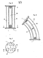
- - la figure 6 représente une coupe longitudinale d'un bras hydraulique selon l'invention,
- - la figure 7'représente une coupe transversale du même bras, et
- - la figure 8 représente une vue du même bras en position déformée.
- FIG. 6 represents a longitudinal section of a hydraulic arm according to the invention,
- FIG. 7 is a cross section of the same arm, and
- - Figure 8 shows a view of the same arm in the deformed position.
Le poignet d'assemblage représenté sur les figures 1 et 2 comporte une membrure-support 1 destinée à être fixée par tout moyen connu en soi à l'extrémité d'un élément porteur, par exemple un bras manipulateur (non représenté). Il comprend également une membrure mobile 2 ( ou plateau mobile) sur laquelle peut être fixé de manière connue en soi un élément porté, par exemple un outil d'assemblage ou une pince de préhension (non représenté). Entre ces deux membrures sont agencés une pluralité de vérins souples 3, 3', 4, 4', 5, 5', 6, 6', 7, 7', 8, 8', 9 et 9'.The assembly wrist shown in FIGS. 1 and 2 comprises a
Comme on peut le voir sur la figure 3, ces vérins sont constitués par un corps sensiblement cylindrique 10, à paroi flexible en forme d'accordéon, solidaire, à chaque extrémité d'une bague 12 rigide de fixation. Au repos, la paroi flexible s'étend autour d'un axe longitudinal 11. Ces vérins sont de préférence hydrauliques et fonctionnent de la manière suivante : lorsque l'on introduit à l'intérieur du vérin un volume d'huile supérieur au volume dudit vérin à l'état de repos, la paroi déformable 10 s'étire, entrainant un éloignement des bagues de fixation 12. Inversement, le retrait d'un volume provoque un tassement de la paroi déformable 10 entrainant un rapprochement des bagues 12 de fixation.As can be seen in FIG. 3, these jacks are constituted by a substantially
Des moyens de commande 13 permettent d'actionner les vérins. Ces moyens de commande 13 comprennent, associé et connecté à chaque vérin, un réservoir de capacité variable (représenté figure 4) comprenant un récipient 14 à paroi rigide auquel est relié au moins un élément à paroi déformable semblable aux vérins souples décrits ci-dessus mais dont la bague de fixation d'une extrémité est fermée. Ces éléments à paroi déformable sont munis de moyens d'entraînement solidaires de l'extrémité fermée. Un déplacement de cette extrémité provoque donc une variation de la capacité du réservoir.Control means 13 make it possible to actuate the jacks. These control means 13 comprise, associated and connected to each jack, a variable capacity tank (shown in FIG. 4) comprising a
La figure 4 montre plusieurs formes de réalisation de ces moyens d'entrainement. Un moteur pas à pas 15 entraIne l'extrémité fermé libre de l'élément à paroi déformable 16. Celui-ci a de préférence un volume au repos égal à celui du vérin souple associé. Un déplacement de l'extrémité libre fermée de l'élément 16, causé par le moteur 15 entraine une variation de la capacité du réservoir. Une quantité d'huile en plus ou en moins dans le réservoir entraîne une quantité d'huile en moins ou en plus dans le vérin souple et actionne celui-ci. On peut également actionner le vérin souple au moyen d'une pluralité d'éléments à paroi déformable 17, 18, 19, 20 dont les volumes sont dans un rapport binaire, c'est-à-dire que le volume de l'élément 17 est moitié de celui de l'élément 18, lui-même moitié de celui de l'élément 19 qui est lui-même moitié de l'élément 20. Ces éléments, ici au nombre de quatre donné à titre d'exemple non limitatif, sont actionnés par des électro-aimants 21 dont l'alimentation est commandée par un système numérique. Si l'élément 17 a un volume égal au quinzième du volume du vérin souple associé, la commande des électro-aimants 21 suivant un système numérique binaire permet le déplacement pas à pas de l'élément porté 2 par rapport à l'élément porteur 1 avec un pas correspondant au quinzième de l'amplitude possible de déplacement.Figure 4 shows several embodiments of these drive means. A stepping
Les liquides n'étant pas entièrement incompressibles et étant susceptibles de variations de volume fonction de variations de température, on peut prévoir un petit élément à paroi déformable 22 commandé par une vis 23 permettant d'effectuer un réglage de compensation.As liquids are not entirely incompressible and being susceptible to volume variations as a function of temperature variations, a small element with a
Chaque vérin souple est muni de moyens de mesure (non représentés) de l'état de sa déformation. Ces moyens de mesure permettent de déterminer avec précision la position exacte de l'élément porté. Reliés aux moyens de commande 13 des moyens d'entrainement 15, 21 des éléments à paroi déformable, il permettent également d'effectuer, en boucle fermée une commande en dimension extrêmement précise. Ces moyens de mesure peuvent par exemple utiliser une détection capacitive, ou un système optique comportant des fibres optiques ou des cellules photo-électriques, ou encore un système à ultra-sons travaillant en phase ou en mode impulsionnel. Il est bien évident que ces moyens de mesure, connus en soi, sont donnés à titre d'exemple non limitatif et que d'autres moyens de mesure peuvent être utilisés.Each flexible cylinder is provided with means for measuring (not shown) the state of its deformation. These measurement means make it possible to precisely determine the exact position of the element worn. Connected to the control means 13 of the drive means 15, 21 of the elements with a deformable wall, they also make it possible to carry out, in closed loop, an extremely precise size control. These measurement means can for example use a capacitive detection, or an optical system comprising optical fibers or photoelectric cells, or even an ultrasound system working in phase or in pulse mode. It is of course tooth that these measuring means, known per se, are given by way of nonlimiting example and that other measuring means can be used.
Il peut être particulièrement intéressant de travailler en mode différentiel, l'ensemble pouvant être, à l'équilibre déjà sous précontrainte ce qui minimise l'effet des déformations parasites.It may be particularly advantageous to work in differential mode, the assembly possibly being, at equilibrium already under prestress, which minimizes the effect of parasitic deformations.
Un tel ensemble est représenté figure 5. Sur cette figure, deux vérins souples 3, 3' sont actionnés par deux réservoirs de capacité variable 14, 14' comportant au moins un élément à paroi déformable 17, 17' actionnés par un électro-aimant à double action muni de deux enroulements d'excitation. L'alimentation d'un de ces enroulements provoque une augmentation de la capacité de l'un des réservoirs et une diminution de la capacité de l'autre réservoir. Ces variations de capacité entraînent une diminution de la hauteur du vérin associé au premier réservoir et une augmentation de la hauteur du vérin associé au second réservoir. La membrure mobile 2, solidaire des extrémités voisines des deux vérins se déplace donc sous l'effet des variations de hauteurs des deux vérins.Such an assembly is shown in FIG. 5. In this figure, two
En plus des moyens de mesure de l'état des déformations de chaque vérin adapté pour commander les moyens d'entrainement des éléments à paroi déformable des réservoirs à capacité variable, on dispose entre les deux réservoirs un détecteur de pression 33 dont le rôle est le suivant : si la membrure mobile 2 est soumise à une contrainte, il se crée à l'intérieur des réservoirs une différence de pression fonction de la grandeur et du sens de la contrainte. Les vérins 3 et 3' étant agencés pour provoquer un déplacement de la membrure mobile 2 dans une direction donnée, la différence de pression détectée entre les réservoirs indique également la direction de la contrainte. Cette indication permet la commande des moyens d'entraînement et lorsque la différence de pression devient nulle, on est assuré que la membrure mobile a atteint la position désirée.In addition to the means for measuring the state of the deformations of each jack adapted to control the means for driving the elements with deformable wall of the tanks with variable capacity, there is between the two tanks a
Dans la forme de réalisation du poignet d'assemblage représenté sur les figures 1 et 2, on a prévu une membrure intermédiaire 24. La membrure-support 1 comporte un corps creux 25 dont les faces internes sont munies de moyens de fixation 26 pour les parois rigides de vérins souples. Sur la figure 2, on peut voir que ces moyens de fixation sont au nombre de Huit formant quatre paires agencées â 90°. Sur ces moyens de fixation est assujettie une extrémité des vérins souples 3, 3', 4, 4', 5, 5', 6 et 6'. La membrure intermédiaire 24 comporte également un corps creux 27 et ses faces externes sont munies de moyens de fixation 28 pour les parois rigides de vérins souples. Sur la figure 2, on peut voir que ces moyens de fixation sont au nombre de quatre répartis à 90°. La membrure intermédiaire 24 est agencée à l'intérieur du corps creux 25 de la membrure support 1 de façon que les moyens de fixations 28 viennent s'intercaler entre les vérins souples 3 et 3', 4 et 4', 5 et 5', 6 et 6'.In the embodiment of the assembly wrist shown in FIGS. 1 and 2, an
La membrure mobile 2 comporte une platine 29 de chaque côté de laquelle est fixée l'une des parois rigides des vérins souples souples 7, 7', 8, 8', 9, 9'. L'autre paroi rigide de ces vérins est fixée à l'intérieur du corps creux 27 de la membrure intermédiaire 24. Ces vérins sont répartis de part et d'autre de la platine 29 selon un angle de 120°.The
Dans l'exemple de réalisation décrit sur les figures 1 et 2, un vérin portant une référence et le vérin portant la même référence accompagnée du signe ' constituent un ensemble différentiel tel qu'il a été décrit en regard de la figure 5.In the exemplary embodiment described in FIGS. 1 and 2, a jack bearing a reference and the jack bearing the same reference accompanied by the sign 'constitute a differential assembly as it has been described with reference to FIG. 5.
Les vérins souples sont répartis en trois groupes dont nous allons expliciter le fonctionnement : un premier groupe Gx, constitué des vérins 3, 3', 4, 4', un deuxième groupe Gy, constitué des vérins 5, 5', 6, 6' et un troisième groupe Gz, constitué des vérins 7, 7', 8, 8', 9, 9'. Lorsque tous les vérins du groupe Gx sont actionnés de façon que les vérins 3 et 4, respectivement 3' et 4' subissent une déformation de même sens, la membrure intermédiaire 24 portant la membrure mobile 2 se déplace suivant une direction marquée X sur la figure 2. De même, lorsque tous les vérins du groupe Gy sont actionnés de façon que les vérins 5 et 6, respectivement 5' et 6' subissent une déformation de même sens, la membrure intermédiaire 24 se déplace suivant une direction marquée Y sur la figure 2. De même, lorsque les trois vérins 7, 8, 9 respectivement 7', 8', 9', sont actionnés de façon à subir des déformations de même sens, la membrure mobile 2 se déplace dans une direction marquée Z sur la figure 1. Les déplacements suivant les directions X, Y, Z sont des déplacements linéaires.The flexible cylinders are divided into three groups whose operation we will explain: a first group Gx, consisting of
En actionnant simultanément les vérins des groupes Gx et Gy de façon que les déformations subies par les vérins 3, 6, 4', 5', respectivement 3', 6', 4, 5 soit de même sens, alors que la membrure intermédiaire effectue par rapport à la membrure support 1 un mouvement de rotation indiqué par sur la figure 2. De même, un actionnement différencié des vérins du groupe Gz entraine un déplacement oscillatoire de la membrure mobile 2 par rapport à la membrure intermédiaire 24 suivant trois directions dont une est indiquée par 9 sur la figure 1. On obtient ainsi un système de liaison mobile à sept degrés de liberté ce qui permet, par une commande individuelle de chaque système différentiel de vérins, d'obtenir des déplacements dans toutes les directions.By simultaneously actuating the cylinders of groups Gx and Gy so that the deformations undergone by the
Dans le cas du poignet mobile d'assemblage qui vient d'être décrit, les déplacements nécessaires de l'élément porté par rapport à l'élément porteur ne sont que de faible amplitude. La grandeur des déplacements étant déterminée par la déformation de la paroi latérale des vérins dans le sens de leur hauteur, celle-ci sera faible et en tout cas inférieure au diamètre desdits vérins.In the case of the movable wrist assembly which has just been described, the necessary displacements of the element carried relative to the carrier element are only of small amplitude. The magnitude of the displacements being determined by the deformation of the side wall of the jacks in the direction of their height, this will be small and in any case less than the diameter of said jacks.
En référence aux figures 6 à 8, il est décrit un dispositif mobile de liaison permettant de faire subir à l'élément porté des déplacements de grande amplitude par rapport à l'élément porteur. Un tel dispositif constitue un bras hydraulique de manutention.With reference to FIGS. 6 to 8, there is described a mobile connection device making it possible to subject the element carried to displacements of great amplitude relative to the carrier element. Such a device constitutes a hydraulic handling arm.
Sur la figure 6, on peut voir la membrure sup- ; port 1 et la membrure mobile 2 constituée toutes deux par une platine circulaire. La membrure 1 est destinée à être fixée sur un châssis porteur (non représenté). Un outil de travail (élément porté non représenté) est fixé sur la membrure mobile 2. Trois vérins 30, 31, 32 sont fixés par leurs bagues de fixation entre les membrures 1 et 2. A chaque vérin est associé et connecté un réservoir à capacité variable semblable à celui décrit ci-dessus. Chaque vérin est également muni de moyens de mesure. Ces trois vérins sont répartis sur les membrures suivant un angle de 120° de façon que leurs axes soient au repos parallèles à une même direction. Les déplacements souhaités étant ici de grande amplitude, les vérins 30, 31, 32 présentent une hauteur nettement plus grande que leur diamètre.In Figure 6, we can see the sup- member ; port 1 and the
L'actionnement différencié de chacun des trois vérins provoque des déplacements fonction de l'état des déformations de chaque vérin. On peut obtenir ainsi un grand nombre de positions dans l'espace.The differentiated actuation of each of the three jacks causes displacements depending on the state of the deformations of each jack. One can thus obtain a large number of positions in space.
Il est évident que l'on peut agencer entre la membrure support 1 et la membrure mobile 2 une ou plusieurs membrures intermédiaires, un groupe de trois vérins étant agencé entre deux membrures voisines, ce qui augmente d'autant le nombre de positions qu'il est possible de donner à l'élément porté.It is obvious that one or more intermediate members can be arranged between the
Un grand avantage des dispositifs de liaison mobile décrits ci-dessus réside dans le fait que les vérins peuvent être commandés à distance, ceux-ci étant reliés aux moyens de commande par un faisceau de conduites hydrauliques et de câbles électriques de mesure.A great advantage of the mobile connection devices described above lies in the fact that the jacks can be controlled remotely, these being connected to the control means by a bundle of hydraulic lines and electrical measurement cables.
Il est à noter que le dispositif conforme à l'invention peut être utilisé pour manoeuvrer en rotation des bras manipulateurs (ou tout autre organe) en permettant un en- trainement de charges importantes ; il suffit d'asservir un point de la membrure mobile de façon à lui imposer un mouvement circulaire.It should be noted that the device according to the invention can be used to maneuver in rotation of the manipulator arms (or any other member) while allowing significant loads to be driven; it suffices to enslave a point on the movable member so as to impose a circular motion on it.
Il est également possible de conférer à la membrure mobile un mouvement alternatif de va-et-vient, par une commande cyclique des vérins.It is also possible to give the movable member an alternating back-and-forth movement, by cyclic control of the jacks.
Claims (19)
Applications Claiming Priority (2)
| Application Number | Priority Date | Filing Date | Title |
|---|---|---|---|
| FR8221389A FR2537909B1 (en) | 1982-12-17 | 1982-12-17 | MOBILE CONNECTION DEVICE FOR SUBJECTING TO A CARRIED ELEMENT MOVEMENTS IN MULTIPLE DEGREES OF FREEDOM |
| FR8221389 | 1982-12-17 |
Publications (2)
| Publication Number | Publication Date |
|---|---|
| EP0113145A1 true EP0113145A1 (en) | 1984-07-11 |
| EP0113145B1 EP0113145B1 (en) | 1986-11-26 |
Family
ID=9280313
Family Applications (1)
| Application Number | Title | Priority Date | Filing Date |
|---|---|---|---|
| EP83201759A Expired EP0113145B1 (en) | 1982-12-17 | 1983-12-13 | Connection device with a plurality of degrees of freedom |
Country Status (6)
| Country | Link |
|---|---|
| US (1) | US4614084A (en) |
| EP (1) | EP0113145B1 (en) |
| JP (1) | JPS60500350A (en) |
| DE (1) | DE3367870D1 (en) |
| FR (1) | FR2537909B1 (en) |
| WO (1) | WO1984002302A1 (en) |
Cited By (11)
| Publication number | Priority date | Publication date | Assignee | Title |
|---|---|---|---|---|
| EP0165635A1 (en) * | 1984-06-13 | 1985-12-27 | Centre National De La Recherche Scientifique (Cnrs) | Joint with several degrees of freedom |
| EP0198134A1 (en) * | 1985-04-17 | 1986-10-22 | International Business Machines Corporation | Remote centre compliance system |
| DE3611806A1 (en) * | 1986-04-08 | 1987-10-15 | Fraunhofer Ges Forschung | Gripper device in particular for an industrial robot |
| GB2191467A (en) * | 1986-06-09 | 1987-12-16 | Teradyne Inc | Compliant link |
| FR2604938A1 (en) * | 1986-09-25 | 1988-04-15 | Peugeot | POSITIONING HEAD |
| EP0278580A1 (en) * | 1987-02-10 | 1988-08-17 | Persluchtring Advies B.V. | A fluid pressure operated push beam and apparatus comprising one or more of such push beams |
| US4790584A (en) * | 1986-06-09 | 1988-12-13 | Teradyne, Inc. | Compliant link |
| FR2692514A1 (en) * | 1992-06-19 | 1993-12-24 | Peugeot | Supple mechanical interface between robot grip and tool it holds - uses plates separated by pneumatic actuators and joined by swivel joint that allows limited three-axis movement. |
| FR2702695A1 (en) * | 1993-03-17 | 1994-09-23 | Irigaray Jean | Device for fitting a polishing or milling tool at the end of a rotating shaft |
| EP1190819A1 (en) * | 2000-03-28 | 2002-03-27 | Seiko Epson Corporation | Pump-integrated flexible actuator |
| EP1586778A3 (en) * | 2001-12-13 | 2006-02-01 | Seiko Epson Corporation | Flexible actuator |
Families Citing this family (8)
| Publication number | Priority date | Publication date | Assignee | Title |
|---|---|---|---|---|
| GB8501654D0 (en) * | 1985-01-23 | 1985-02-27 | Emi Ltd | Compliant coupling mechanism |
| FR2590196B1 (en) * | 1985-11-15 | 1991-04-19 | Havez Bernard | HANDLING DEVICE |
| DE3821548A1 (en) * | 1988-03-22 | 1989-10-05 | Mannesmann Ag | DEVICE FOR COMPENSATING POSITION AND POSITION TOLERANCES |
| US5116190A (en) * | 1990-08-02 | 1992-05-26 | General Atomics | Remotely adjustable compliance for end effector tooling |
| US5377950A (en) * | 1992-09-10 | 1995-01-03 | The University Of British Columbia | Platform mountings |
| DE102010035561B3 (en) * | 2010-08-26 | 2012-01-19 | Wsengineering Gmbh & Co.Kg | Tool holder with evasive mechanism and method for its production |
| DE102013204588A1 (en) * | 2013-03-15 | 2014-09-18 | Siemens Aktiengesellschaft | Torque transmission device, actuator, robot |
| JP2015169386A (en) * | 2014-03-07 | 2015-09-28 | 三菱電機株式会社 | Air conditioner |
Citations (10)
| Publication number | Priority date | Publication date | Assignee | Title |
|---|---|---|---|---|
| CH290405A (en) * | 1950-07-28 | 1953-04-30 | Anstalt Gibone | Device for hydraulic power transmission. |
| US3279624A (en) * | 1962-09-26 | 1966-10-18 | George C Devol | Programmed article handling |
| US3284964A (en) * | 1964-03-26 | 1966-11-15 | Saito Norio | Flexible beam structures |
| FR1500113A (en) * | 1966-07-13 | 1967-11-03 | Siersatom S A | Multi-orientation arm |
| FR2032026A5 (en) * | 1969-02-17 | 1970-11-20 | Beaudouin Ets | |
| FR2328950A1 (en) * | 1975-10-24 | 1977-05-20 | Kilchsperger Jean Claude | Reciprocating liq. column metering pump - has oscillating liq. and buffer liq. between piston drive diaphragm and valved diaphragm pump |
| US4060178A (en) * | 1974-05-10 | 1977-11-29 | Miller Mfg. Co. Of Schiller Park, Inc. | Metering pump |
| US4099409A (en) * | 1977-07-05 | 1978-07-11 | The Bendix Corporation | Multi-axis load cell with arcuate flexures |
| GB2033010A (en) * | 1978-10-12 | 1980-05-14 | Automotive Prod Co Ltd | Fluid pressure servo motors |
| EP0017016A1 (en) * | 1979-03-16 | 1980-10-15 | Robotgruppen HB | Flexible arm, particularly a robot arm |
Family Cites Families (4)
| Publication number | Priority date | Publication date | Assignee | Title |
|---|---|---|---|---|
| US2780065A (en) * | 1955-07-20 | 1957-02-05 | Letourneau Westinghouse Compan | Closed hydraulic system |
| US2927432A (en) * | 1958-03-18 | 1960-03-08 | Ibm | Hydraulic positioning device |
| US3583752A (en) * | 1968-01-02 | 1971-06-08 | Ibm | Vibratory article handling device |
| GB2088504B (en) * | 1980-11-27 | 1984-12-19 | Underwater & Marine Equipment | Flexible tubular joint |
-
1982
- 1982-12-17 FR FR8221389A patent/FR2537909B1/en not_active Expired
-
1983
- 1983-12-12 US US06/641,964 patent/US4614084A/en not_active Expired - Fee Related
- 1983-12-12 WO PCT/FR1983/000249 patent/WO1984002302A1/en unknown
- 1983-12-12 JP JP59500222A patent/JPS60500350A/en active Pending
- 1983-12-13 DE DE8383201759T patent/DE3367870D1/en not_active Expired
- 1983-12-13 EP EP83201759A patent/EP0113145B1/en not_active Expired
Patent Citations (10)
| Publication number | Priority date | Publication date | Assignee | Title |
|---|---|---|---|---|
| CH290405A (en) * | 1950-07-28 | 1953-04-30 | Anstalt Gibone | Device for hydraulic power transmission. |
| US3279624A (en) * | 1962-09-26 | 1966-10-18 | George C Devol | Programmed article handling |
| US3284964A (en) * | 1964-03-26 | 1966-11-15 | Saito Norio | Flexible beam structures |
| FR1500113A (en) * | 1966-07-13 | 1967-11-03 | Siersatom S A | Multi-orientation arm |
| FR2032026A5 (en) * | 1969-02-17 | 1970-11-20 | Beaudouin Ets | |
| US4060178A (en) * | 1974-05-10 | 1977-11-29 | Miller Mfg. Co. Of Schiller Park, Inc. | Metering pump |
| FR2328950A1 (en) * | 1975-10-24 | 1977-05-20 | Kilchsperger Jean Claude | Reciprocating liq. column metering pump - has oscillating liq. and buffer liq. between piston drive diaphragm and valved diaphragm pump |
| US4099409A (en) * | 1977-07-05 | 1978-07-11 | The Bendix Corporation | Multi-axis load cell with arcuate flexures |
| GB2033010A (en) * | 1978-10-12 | 1980-05-14 | Automotive Prod Co Ltd | Fluid pressure servo motors |
| EP0017016A1 (en) * | 1979-03-16 | 1980-10-15 | Robotgruppen HB | Flexible arm, particularly a robot arm |
Cited By (17)
| Publication number | Priority date | Publication date | Assignee | Title |
|---|---|---|---|---|
| EP0165635A1 (en) * | 1984-06-13 | 1985-12-27 | Centre National De La Recherche Scientifique (Cnrs) | Joint with several degrees of freedom |
| EP0198134A1 (en) * | 1985-04-17 | 1986-10-22 | International Business Machines Corporation | Remote centre compliance system |
| DE3611806A1 (en) * | 1986-04-08 | 1987-10-15 | Fraunhofer Ges Forschung | Gripper device in particular for an industrial robot |
| US4790584A (en) * | 1986-06-09 | 1988-12-13 | Teradyne, Inc. | Compliant link |
| GB2191467A (en) * | 1986-06-09 | 1987-12-16 | Teradyne Inc | Compliant link |
| GB2191467B (en) * | 1986-06-09 | 1989-12-20 | Teradyne Inc | Compliant link |
| FR2604938A1 (en) * | 1986-09-25 | 1988-04-15 | Peugeot | POSITIONING HEAD |
| EP0266236A1 (en) * | 1986-09-25 | 1988-05-04 | Automobiles Peugeot | Positioning holder |
| EP0278580A1 (en) * | 1987-02-10 | 1988-08-17 | Persluchtring Advies B.V. | A fluid pressure operated push beam and apparatus comprising one or more of such push beams |
| US4928926A (en) * | 1987-02-10 | 1990-05-29 | Persluchtring Advies B.V. | Fluid pressure operated push beam and apparatus comprising one or more of such push beams |
| FR2692514A1 (en) * | 1992-06-19 | 1993-12-24 | Peugeot | Supple mechanical interface between robot grip and tool it holds - uses plates separated by pneumatic actuators and joined by swivel joint that allows limited three-axis movement. |
| FR2702695A1 (en) * | 1993-03-17 | 1994-09-23 | Irigaray Jean | Device for fitting a polishing or milling tool at the end of a rotating shaft |
| EP1190819A1 (en) * | 2000-03-28 | 2002-03-27 | Seiko Epson Corporation | Pump-integrated flexible actuator |
| EP1190819A4 (en) * | 2000-03-28 | 2003-04-09 | Seiko Epson Corp | Pump-integrated flexible actuator |
| US6718766B2 (en) | 2000-03-28 | 2004-04-13 | Seiko Epson Corporation | Pump-integrated flexible actuator |
| EP1408241A3 (en) * | 2000-03-28 | 2004-11-17 | Seiko Epson Corporation | Pump-integrated flexible actuator |
| EP1586778A3 (en) * | 2001-12-13 | 2006-02-01 | Seiko Epson Corporation | Flexible actuator |
Also Published As
| Publication number | Publication date |
|---|---|
| JPS60500350A (en) | 1985-03-14 |
| US4614084A (en) | 1986-09-30 |
| WO1984002302A1 (en) | 1984-06-21 |
| FR2537909A1 (en) | 1984-06-22 |
| DE3367870D1 (en) | 1987-01-15 |
| EP0113145B1 (en) | 1986-11-26 |
| FR2537909B1 (en) | 1987-06-26 |
Similar Documents
| Publication | Publication Date | Title |
|---|---|---|
| EP0113145B1 (en) | Connection device with a plurality of degrees of freedom | |
| EP1879827B1 (en) | Sling device for a piece with force compensation and hoisting system comprising the same | |
| EP0080416B1 (en) | Drive mechanism and its application to a position remote control for a master-slave manipulator | |
| WO1999038044A1 (en) | Assembly for mounting and correcting the position of an element, such as a mirror, of a space telescope | |
| FR2556274A1 (en) | HANDLING ROBOT FOR BOTTOM PIECES | |
| EP0551045A1 (en) | Device for controlling the dimensions of an object, in particular the external or internal diameters of mechanical pieces | |
| FR2561394A1 (en) | DEVICE FOR RECEIVING ACOUSTIC WAVES IN A WELL | |
| EP0165635B1 (en) | Joint with several degrees of freedom | |
| FR2695767A1 (en) | Rotary piezoelectric motor with improved stator-housing connection. | |
| EP0479653B1 (en) | Mounting assembly for a loading platform which is retractable parallel to the chassis of a vehicle | |
| FR2880575A1 (en) | Delta type parallel manipulator robot for moving light load, has load balancing unit balancing load exerted on movable unit and permitting mobility of connection with respect to base unit according to three degrees of liberty and pantograph | |
| EP0003930B1 (en) | Apparatus for simultaneously applying several optical fibres into several helicoidal grooves on the surface of a cylindrical support | |
| FR2483300A1 (en) | Articulated mechanical handling arm - is on swivel base and uses two fixed jacks to counter torque at joints and moment of front arm about shoulder joint | |
| EP0122208A1 (en) | Device for conveying rotary motion from a driving to a driven shaft | |
| EP0074888A2 (en) | Load-handling device and application to immersed-load handling | |
| FR2627718A1 (en) | FORCE BALANCING DEVICE, ESPECIALLY WEIGHING, ACTING ON A ROBOT ARM OR THE LIKE | |
| EP0086710B1 (en) | Three-dimensional cam command for use as part of a multi-parameter function calculator | |
| WO2006059039A1 (en) | Haptic interface comprising cables | |
| FR2794196A1 (en) | Measurement and continuous display of actuator rod position utilizes cable connected at end to rod and wound round rotating drum | |
| FR2467169A1 (en) | Tower crane with permanent balancing - has base supports with monitors to measure side loads and control counter-balance weight | |
| EP0498699A1 (en) | Pointing mechanism for a payload, especially for a satellite antenna | |
| EP0171763B1 (en) | Self-centering device for guiding a measuring instrument or tool relative to an oblong object | |
| EP0806601A2 (en) | Supporting system for a large apparatus, particularly an optical bench | |
| WO2024089357A1 (en) | Three-degrees-of-freedom joint with force feedback | |
| FR2599289A1 (en) | Mechanical three-jaw gripper particularly intended for a robot |
Legal Events
| Date | Code | Title | Description |
|---|---|---|---|
| PUAI | Public reference made under article 153(3) epc to a published international application that has entered the european phase |
Free format text: ORIGINAL CODE: 0009012 |
|
| AK | Designated contracting states |
Designated state(s): CH DE GB IT LI NL SE |
|
| 17P | Request for examination filed |
Effective date: 19841119 |
|
| GRAA | (expected) grant |
Free format text: ORIGINAL CODE: 0009210 |
|
| AK | Designated contracting states |
Kind code of ref document: B1 Designated state(s): CH DE GB IT LI NL SE |
|
| REF | Corresponds to: |
Ref document number: 3367870 Country of ref document: DE Date of ref document: 19870115 |
|
| ITF | It: translation for a ep patent filed |
Owner name: ORGANIZZAZIONE D'AGOSTINI |
|
| PLBE | No opposition filed within time limit |
Free format text: ORIGINAL CODE: 0009261 |
|
| STAA | Information on the status of an ep patent application or granted ep patent |
Free format text: STATUS: NO OPPOSITION FILED WITHIN TIME LIMIT |
|
| 26N | No opposition filed | ||
| PGFP | Annual fee paid to national office [announced via postgrant information from national office to epo] |
Ref country code: SE Payment date: 19891123 Year of fee payment: 7 |
|
| PGFP | Annual fee paid to national office [announced via postgrant information from national office to epo] |
Ref country code: CH Payment date: 19891213 Year of fee payment: 7 |
|
| PGFP | Annual fee paid to national office [announced via postgrant information from national office to epo] |
Ref country code: NL Payment date: 19891231 Year of fee payment: 7 Ref country code: GB Payment date: 19891231 Year of fee payment: 7 |
|
| PGFP | Annual fee paid to national office [announced via postgrant information from national office to epo] |
Ref country code: DE Payment date: 19900223 Year of fee payment: 7 |
|
| PG25 | Lapsed in a contracting state [announced via postgrant information from national office to epo] |
Ref country code: GB Effective date: 19901213 |
|
| PG25 | Lapsed in a contracting state [announced via postgrant information from national office to epo] |
Ref country code: SE Effective date: 19901214 |
|
| PG25 | Lapsed in a contracting state [announced via postgrant information from national office to epo] |
Ref country code: LI Effective date: 19901231 Ref country code: CH Effective date: 19901231 |
|
| PG25 | Lapsed in a contracting state [announced via postgrant information from national office to epo] |
Ref country code: NL Effective date: 19910701 |
|
| GBPC | Gb: european patent ceased through non-payment of renewal fee | ||
| NLV4 | Nl: lapsed or anulled due to non-payment of the annual fee | ||
| REG | Reference to a national code |
Ref country code: CH Ref legal event code: PL |
|
| PG25 | Lapsed in a contracting state [announced via postgrant information from national office to epo] |
Ref country code: DE Effective date: 19910903 |
|
| EUG | Se: european patent has lapsed |
Ref document number: 83201759.4 Effective date: 19910910 |