EP0806601A2 - Supporting system for a large apparatus, particularly an optical bench - Google Patents
Supporting system for a large apparatus, particularly an optical bench Download PDFInfo
- Publication number
- EP0806601A2 EP0806601A2 EP97400963A EP97400963A EP0806601A2 EP 0806601 A2 EP0806601 A2 EP 0806601A2 EP 97400963 A EP97400963 A EP 97400963A EP 97400963 A EP97400963 A EP 97400963A EP 0806601 A2 EP0806601 A2 EP 0806601A2
- Authority
- EP
- European Patent Office
- Prior art keywords
- chassis
- jacks
- supports
- freedom
- articulated
- Prior art date
- Legal status (The legal status is an assumption and is not a legal conclusion. Google has not performed a legal analysis and makes no representation as to the accuracy of the status listed.)
- Withdrawn
Links
Images

Classifications
-
- F—MECHANICAL ENGINEERING; LIGHTING; HEATING; WEAPONS; BLASTING
- F16—ENGINEERING ELEMENTS AND UNITS; GENERAL MEASURES FOR PRODUCING AND MAINTAINING EFFECTIVE FUNCTIONING OF MACHINES OR INSTALLATIONS; THERMAL INSULATION IN GENERAL
- F16M—FRAMES, CASINGS OR BEDS OF ENGINES, MACHINES OR APPARATUS, NOT SPECIFIC TO ENGINES, MACHINES OR APPARATUS PROVIDED FOR ELSEWHERE; STANDS; SUPPORTS
- F16M7/00—Details of attaching or adjusting engine beds, frames, or supporting-legs on foundation or base; Attaching non-moving engine parts, e.g. cylinder blocks
-
- G—PHYSICS
- G01—MEASURING; TESTING
- G01M—TESTING STATIC OR DYNAMIC BALANCE OF MACHINES OR STRUCTURES; TESTING OF STRUCTURES OR APPARATUS, NOT OTHERWISE PROVIDED FOR
- G01M11/00—Testing of optical apparatus; Testing structures by optical methods not otherwise provided for
- G01M11/02—Testing optical properties
- G01M11/04—Optical benches therefor
Landscapes
- Engineering & Computer Science (AREA)
- General Engineering & Computer Science (AREA)
- Mechanical Engineering (AREA)
- Chemical & Material Sciences (AREA)
- Analytical Chemistry (AREA)
- Physics & Mathematics (AREA)
- General Physics & Mathematics (AREA)
- Telescopes (AREA)
Abstract
Description
La présente invention concerne un système pour supporter un appareillage de grandes dimensions, en particulier un banc optique.The present invention relates to a system for supporting a device of large dimensions, in particular an optical bench.
Dans le domaine optique, les appareillages sont le plus souvent constitués par un ensemble de composants répartis en plusieurs étages successifs qu'il faut positionner avec précision les uns par rapports aux autres.In the optical field, the apparatuses most often consist of a set of components distributed in several successive stages which must be positioned with precision with respect to each other.
D'une manière générale, l'ensemble des composants est monté sur un châssis auquel on demande de remplir un certain nombre de fonctions qui sont nécessaires pour assurer une bonne fiabilité de fonctionnement du banc optique.Generally, all of the components are mounted on a chassis which is asked to fulfill a certain number of functions which are necessary to ensure good operating reliability of the optical bench.
Parmi ces fonctions, on peut notamment citer celles qui consistent :
- à isoler le banc optique des vibrations,
- à éviter des déformations et des contraintes mécaniques pouvant résulter de variations de températures, par exemple,
- à rattraper les dérives long terme de la géométrie du sol,
- à être fiable, robuste et de longue durée,
- à faciliter les opérations de maintenance lorsqu'un élément du châssis est défectueux, et
- à pouvoir éventuellement repositionner le banc optique suivant les six degrés de liberté.
- isolating the optical bench from vibrations,
- to avoid deformations and mechanical stresses which may result from temperature variations, for example,
- to catch up with long-term drifts in soil geometry,
- to be reliable, robust and long lasting,
- to facilitate maintenance operations when a part of the chassis is defective, and
- to be able to possibly reposition the optical bench according to the six degrees of freedom.
Cependant, pour définir la structure du châssis, il faut également tenir compte du fait que le banc optique ne constitue pas nécessairement une charge homogène. En effet, la charge peut être non seulement lourde mais également hétérogène du fait qu'elle comprend par exemple, plusieurs étages qui n'ont pas nécessairement la même structure et donc la même masse. Il peut alors en résulter un comportement mécanique complexe qu'il faut alors maîtriser.However, when defining the chassis structure, it must also be taken into account that the optical bench does not necessarily constitute a homogeneous load. Indeed, the load can be not only heavy but also heterogeneous because it comprises for example, several stages which do not necessarily have the same structure and therefore the same mass. This can then result in a complex mechanical behavior which must then be mastered.
Pour supporter des bancs optiques de grandes dimensions, c'est-à-dire qui présentent une grande longueur et/ou une grande surface, il est essentiellement connu deux architectures de châssis.To support large optical benches, that is to say which have a long length and / or a large surface, it is essentially known two chassis architectures.
Selon une première architecture connue, le châssis est rigide et formé d'une seule pièce qui repose ou est fixée au sol. Cette solution, bien que simple, présente toutefois l'inconvénient de conduire à un châssis de masse importante non repositionnable dans l'espace suivant les six degrés de liberté.According to a first known architecture, the chassis is rigid and formed in one piece which rests or is fixed to the ground. This solution, although simple, however has the drawback of leading to a chassis of large mass which cannot be repositioned in space according to the six degrees of freedom.
Selon une seconde architecture connue, le châssis est scindé en plusieurs segments, mais cette solution nécessite alors des ajustements délicats entre les différents segments du châssis pour les positionner correctement les uns par rapport aux autres. Cette solution permet cependant de pouvoir envisager un repositionnement actif de chaque segment par rapport aux autres segments du châssis, mais cela conduit à un nombre élevé de points de mesure, à des actionneurs qui sont actifs en permanence et à un nombre important de boucles d'asservissement. Autrement dit, il en résulte une architecture complexe et délicate à mettre en oeuvre.According to a second known architecture, the chassis is split into several segments, but this solution then requires delicate adjustments between the different segments of the chassis to position them correctly with respect to each other. This solution however makes it possible to be able to envisage an active repositioning of each segment relative to the other segments of the chassis, but this leads to a high number of measurement points, to actuators which are permanently active and to a large number of loops. enslavement. In other words, this results in a complex and delicate architecture to be implemented.
Le but de l'invention est de proposer une nouvelle architecture de support d'un appareillage de grandes dimensions, qui pallie notamment les inconvénients précités.The object of the invention is to propose a new architecture for supporting a device of large dimensions, which in particular overcomes the aforementioned drawbacks.
Pour atteindre ce but, l'invention propose un système pour supporter un appareillage de grandes dimensions, en particulier un banc optique, l'appareillage comprenant un ensemble de composants montés sur un châssis d'une seule pièce, système qui est caractérisé en ce qu'il est du type isostatique et comprend au moins un ensemble de supports sensiblement verticaux constitués par des vérins qui sont articulés d'une part, à une structure fixe et, d'autres part, au châssis pour définir des points d'appui sur lequel le châssis est posé et/ou des points de suspension auxquels le châssis est suspendu, la position et le nombre de ces points d'appui et/ou de suspension étant choisis pour que la masse du châssis soit régulièrement répartie entre ces différents points, et en ce que les vérins formant les supports verticaux sont alimentés en fluide sous pression à partir de plusieurs réseaux hydrauliques.To achieve this object, the invention provides a system for supporting large-sized switchgear, in particular an optical bench, the switchgear comprising a set of components mounted on a chassis in one piece, a system which is characterized in that '' it is of the isostatic type and comprises at least one set of substantially vertical supports constituted by jacks which are articulated on the one hand, to a fixed structure and, on the other hand, to the chassis to define support points on which the chassis is placed and / or suspension points to which the chassis is suspended, the position and the number of these support and / or suspension points being chosen so that the mass of the chassis is regularly distributed between these different points, and in that the jacks forming the vertical supports are supplied with pressurized fluid from several hydraulic networks.
Selon une autre caractéristique de l'invention, les vérins formant les supports verticaux sont répartis en plusieurs ensembles pour pouvoir contrôler plusieurs degrés de liberté, les vérins de chaque ensemble étant alimentés à partir d'un réseau hydraulique actif relié à une unité de dosage de fluide pour repositionner le châssis suivant le degré de liberté contrôlé par chaque ensemble de vérins.According to another characteristic of the invention, the jacks forming the vertical supports are divided into several assemblies in order to be able to control several degrees of freedom, the jacks of each assembly being supplied from an active hydraulic network connected to a metering unit for fluid to reposition the chassis according to the degree of freedom controlled by each set of cylinders.
D'une manière générale, le châssis est par exemple de forme parallélépipédique rectangle avec deux faces respectivement supérieure et inférieure, deux faces latérales longitudinales et deux faces latérales d'extrémité, les points d'appui et/ou de suspension du châssis étant situés sur les faces supérieure et/ou inférieure de celui-ci, le système comprenant également des supports latéraux qui sont articulés, d'une part, à la structure fixe et, d'autre part, à une face latérale longitudinale du châssis, ainsi que des supports d'extrémité qui sont articulés d'une part, à la structure fixe et, d'autre part, à une face latérale d'extrémité du châssis, les supports latéraux et d'extrémité étant avantageusement constitués par des vérins.In general, the chassis is for example of rectangular parallelepiped shape with two upper and lower faces respectively, two longitudinal side faces and two lateral end faces, the support and / or suspension points of the chassis being located on the upper and / or lower faces thereof, the system also comprising lateral supports which are articulated, on the one hand, to the fixed structure and, on the other hand, to a longitudinal lateral face of the chassis, as well as end supports which are articulated on the one hand, to the fixed structure and, on the other hand, to a lateral end face of the chassis, the lateral and end supports advantageously being constituted by jacks.
Le système supporte le châssis d'une manière isostatique par l'intermédiaire des vérins formant les supports verticaux, latéraux et d'extrémité alimentés en fluide sous pression par des réseaux hydrauliques, sachant qu'il est également possible de repositionner le châssis suivant plusieurs degrés de liberté en rendant actif cet isostatisme en dosant le fluide d'alimentation des vérins à travers les réseaux hydrauliques.The system supports the chassis in an isostatic way by means of the jacks forming the vertical, lateral and end supports supplied with pressurized fluid by hydraulic networks, knowing that it is also possible to reposition the chassis according to several degrees freedom by making this isostatism active by dosing the fluid supplying the cylinders through the hydraulic networks.
Selon un mode de réalisation du système selon l'invention :
- les vérins des supports verticaux qui définissent les points d'appui et/ou de suspension du châssis sont répartis suivant trois réseaux hydrauliques actifs pour assurer en plus un contrôle du positionnement du châssis suivant trois degrés de liberté,
- les supports latéraux du système sont constitués par des vérins qui sont avantageusement répartis suivant deux réseaux hydrauliques actifs pour assurer en plus un contrôle du positionnement du châssis suivant deux autres degrés de liberté, et
- les supports d'extrémité du système sont constitués par au moins un vérin relié à un réseau hydraulique actif pour assurer un contrôle suivant le sixième degré de liberté.
- the cylinders of the vertical supports which define the support and / or suspension points of the chassis are distributed along three active hydraulic networks to additionally provide control of the positioning of the chassis according to three degrees of freedom,
- the lateral supports of the system are constituted by jacks which are advantageously distributed along two active hydraulic networks in addition to ensuring control of the positioning of the chassis according to two other degrees of freedom, and
- the end supports of the system consist of at least one jack connected to an active hydraulic network to ensure control according to the sixth degree of freedom.
Ainsi, selon ce premier mode de réalisation, le châssis peut être posé ou suspendu au système de support avec possibilité de repositionner dans l'espace le châssis puisque le système permet de modifier la position du châssis suivant les six degrés de liberté. Bien entendu, une solution mixte posé et suspension peut être envisagée pour supporter le châssis.Thus, according to this first embodiment, the chassis can be placed or suspended from the support system with the possibility of repositioning the chassis in space since the system makes it possible to modify the position of the chassis according to the six degrees of freedom. Of course, a mixed solution posed and suspension can be envisaged to support the chassis.
En variante de ce premier mode de réalisation, les supports latéraux et/ou d'extrémité du système peuvent être constitués par des biellettes articulées.As a variant of this first embodiment, the lateral and / or end supports of the system can be constituted by articulated rods.
Selon un second mode de réalisation qui est plus particulièrement adapté dans le cas d'un châssis long, haut et étroit qui est suspendu au système de support :
- les vérins des supports verticaux qui définissent les points de suspension du châssis sont répartis suivant deux réseaux hydrauliques actifs pour assurer un contrôle du positionnement du châssis suivant deux degrés de liberté,
- les supports latéraux du système sont constitués par des vérins qui sont répartis suivant trois réseaux hydrauliques actifs pour assurer un contrôle du positionnement du châssis suivant trois autres degrés de liberté, et
- les supports d'extrémité du système sont constitués par au moins un vérin relié à un réseau hydraulique actif pour assurer le contrôle du positionnement du châssis suivant le sixième degré de liberté.
- the cylinders of the vertical supports which define the suspension points of the chassis are distributed along two active hydraulic networks to ensure control of the positioning of the chassis according to two degrees of freedom,
- the lateral supports of the system consist of cylinders which are distributed according to three active hydraulic networks to ensure control of the positioning of the chassis according to three other degrees of freedom, and
- the system end supports consist of at least one cylinder connected to an active hydraulic network to control the positioning of the chassis according to the sixth degree of freedom.
En variante de ce second mode de réalisation, les supports d'extrémité du système peuvent être constitués par des biellettes articulées.As a variant of this second embodiment, the end supports of the system can be constituted by articulated rods.
D'une manière générale, chaque réseau hydraulique actif est relié à une unité de dosage indépendante qui alimente en fluide les vérins du réseau.In general, each active hydraulic network is connected to an independent metering unit which supplies the cylinders in the network with fluid.
Dans les modes de réalisation envisagés précédemment, chaque vérin comporte par exemple un corps creux dans lequel est monté un piston coulissant qui partage le volume intérieur du corps du vérin en deux chambres à volume variable, le piston se prolongeant d'un côté par une tige qui fait saillie à l'extérieur du corps du vérin, le corps du vérin étant articulé à la structure fixe alors que l'extrémité libre de la tige de piston est articulée au châssis.In the embodiments envisaged above, each cylinder comprises for example a hollow body in which is mounted a sliding piston which divides the internal volume of the cylinder body into two variable-volume chambers, the piston extending on one side by a rod which projects outside the cylinder body, the cylinder body being articulated to the fixed structure while the free end of the piston rod is articulated to the chassis.
Dans cet exemple, une chambre des vérins des supports verticaux, aussi bien dans le cas d'un châssis posé que suspendu, est alimentée en fluide sous pression, alors que l'autre chambre de ces vérins est mise à l'échappement par l'intermédiaire d'un clapet, par exemple.In this example, one of the cylinders of the vertical supports, both in the case of a seated and suspended chassis, is supplied with pressurized fluid, while the other chamber of these jacks is exhausted by the through a valve, for example.
Au contraire, les deux chambres des vérins des supports latéraux ou d'extrémité sont toutes les deux remplies de fluide, alors que l'une des chambres communique également avec un accumulateur hydraulique.On the contrary, the two chambers of the cylinders of the lateral or end supports are both filled with fluid, while one of the chambers also communicates with a hydraulic accumulator.
En variante, chaque vérin pourrait être un vérin à membrane déformable.Alternatively, each cylinder could be a cylinder with a deformable membrane.
Le système est complété par des capteurs de position qui sont répartis le long du châssis pour permettre à une unité centrale de commander les différentes unités de dosage des réseaux hydrauliques en fonction des informations transmises par les capteurs pour repositionner le châssis suivant les degrés de liberté autorisés par le système.The system is completed by position sensors which are distributed along the chassis to allow a central unit to control the different metering units of the hydraulic networks according to the information transmitted by the sensors to reposition the chassis according to the authorized degrees of freedom by the system.
Le système selon l'invention permet donc de supporter d'une manière isostatique, active ou non, le châssis de l'appareillage, ce qui offre notamment l'avantage de pouvoir utiliser un châssis d'une seule pièce mais dont la masse est notablement réduite.The system according to the invention therefore makes it possible to support in an isostatic manner, active or not, the chassis of the apparatus, which in particular offers the advantage of being able to use a chassis in one piece but whose mass is notably scaled down.
Le système selon l'invention permet de remplir les fonctions énumérées en préambule, mais il permet également de réduire les flexions parasites du châssis sous l'effet de la gravité, ainsi que les défauts géométriques d'alignement des interfaces de liaison des supports verticaux, latéraux et d'extrémité sur le châssis et sur le sol, ce qui facilite les opérations de montage du système.The system according to the invention makes it possible to fulfill the functions listed in the preamble, but it also makes it possible to reduce the parasitic flexions of the chassis under the effect of gravity, as well as the geometrical defects of alignment of the interfaces for connecting the vertical supports, side and end on the chassis and on the ground, which facilitates the assembly operations of the system.
D'autres avantages, caractéristiques et détails de l'invention ressortiront de la description explicative qui va suivre, faite en référence aux dessins annexés, donnés uniquement à titre d'exemple et dans lesquels :
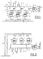
- la figure 1 est une vue schématique partielle pour illustrer le principe du système selon un mode de réalisation de l'invention lorsque le châssis de l'appareillage est posé sur le système de support,
- la figure 2 est une vue en perspective simplifiée pour illustrer les réseaux hydrauliques qui alimentent les vérins du système de la figure 1,
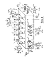
- les figures 3 et 4 sont des vues schématiques semblables aux figures 1 et 2 dans le cas où le châssis est suspendu au système de support selon l'invention ,
- les figures 5 et 6 sont des vues schématiques pour illustrer une variante de réalisation du système représenté aux figures 1 et 2, et
- les figures 7 et 8 sont des vues schématiques pour illustrer un autre mode de réalisation du système selon l'invention.
- FIG. 1 is a partial schematic view to illustrate the principle of the system according to one embodiment of the invention when the chassis of the apparatus is placed on the support system,
- FIG. 2 is a simplified perspective view to illustrate the hydraulic networks which supply the jacks of the system of FIG. 1,
- FIGS. 3 and 4 are schematic views similar to FIGS. 1 and 2 in the case where the chassis is suspended from the support system according to the invention,
- FIGS. 5 and 6 are schematic views to illustrate an alternative embodiment of the system shown in FIGS. 1 and 2, and
- Figures 7 and 8 are schematic views to illustrate another embodiment of the system according to the invention.
Les composants 1a, 1b, 1c.... d'un appareillage tel qu'un banc optique 1 par exemple, sont montés sur un châssis 3 formé d'une seule pièce et qui est supporté d'une manière isostatique par un système selon l'invention.The
Pour des raisons de simplification, le châssis 3 est schématisé sous la forme d'un parallélépipédique sensiblement rectangle sur lequel on distinguera les deux faces supérieure 3a et inférieure 3b, les deux faces latérales longitudinales 3c et les deux faces d'extrémité 3d.For reasons of simplification, the
Selon un exemple de réalisation illustré sur les figures 1 et 2, les composants 1a, 1b, 1c.... du banc optique 1 sont montés sur la face supérieure 3a du châssis 3, ce châssis 3 reposant par sa face inférieure 3b sur le système selon l'inventionAccording to an exemplary embodiment illustrated in FIGS. 1 and 2, the
Le système comprend notamment un ensemble de supports sensiblement verticaux tels que des vérins 7, du type hydraulique par exemple. Chaque vérin 7 peut être constitué, d'une façon connue en soi, par un corps creux 9 dans lequel est monté coulissant un piston 10 qui partage ainsi le volume intérieur du corps 9 en deux chambres A et B à volume variable. Du côté de la chambre B, le piston 10 se prolonge par une tige de piston 12 dont l'extrémité libre fait saillie à l'extérieur du vérin 7.The system notably comprises a set of substantially vertical supports such as
Le corps 9 de chaque vérin 7 est monté articulé en 15 sur une embase fixe 17 qui repose sur le sol, alors que l'extrémité libre de la tige de piston 12 est montée articulée en 19 à la face inférieure 3b du châssis 3. Les articulations 15 et 19 sont des rotules, par exemple.The
Dans l'exemple illustré, le châssis 3 est supporté par douze vérins 7 (figure 2), le nombre et la position de ces vérins 7 étant déterminés en fonction des dimensions et de la masse du châssis 3, de manière à ce que ce dernier soit supporté sans déformation et contrainte mécanique excessives et que sa masse soit régulièrement répartie ou équilibrée sur l'ensemble des points d'appui 19 du système et en évitant tout hyperstatisme.In the example illustrated, the
Avantageusement, le système support est du type isostatique actif pour permettre un repositionnement du châssis 3 suivant plusieurs degrés de liberté.Advantageously, the support system is of the active isostatic type to allow repositioning of the
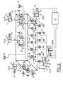
A cet effet, les douze vérins 7 sont répartis en trois réseaux hydrauliques actifs R1, R2 et R3 qui comprennent chacun quatre vérins 7.To this end, the twelve
Les quatre vérins 7 du réseau hydraulique R1 sont commandés à partir d'une unité de dosage U1 qui alimente simultanément en fluide les chambres inférieures A des vérins 7, alors que les chambres supérieures B sont mises à l'échappement par un clapet 21. Les chambres A des vérins 7 sont raccordées par des tubulures flexibles t à l'unité U1. Il en est de même pour l'alimentation des vérins des réseaux hydrauliques R2 et R3 qui sont alimentés à partir d'unités de dosage U2 et U3, respectivement.The four
Chaque unité de dosage U1, U2 et U3 est par exemple constituée par un vérin 23 qui comprend une chambre C à volume variable remplie d'un fluide qui est acheminé dans les tubulures t des réseaux hydrauliques R1 à R3 par un piston 25 mobile en translation et commandé par une unité centrale UC qui est reliée aux unités de dosage U1, U2 et U3.Each metering unit U1, U2 and U3 is for example constituted by a
Lorsqu'un positionnement du châssis 3 dans l'espace n'est pas nécessaire, les unités de dosage sont alors supprimées, les réseaux hydrauliques étant alors passifs.When a positioning of the
Le système comprend également des supports latéraux qui sont constitués par des vérins 7. Le corps 9 de chaque vérin est monté articulé en 27 sur un montant vertical 29 qui est ou non solidaire de l'embase 17, alors que l'extrémité libre de la tige de piston 12 est montée articulée en 31 sur une face longitudinale 3c du châssis 3. Les articulations 27 et 31 sont des rotules par exemple.The system also includes lateral supports which are constituted by
Dans cet exemple, le nombre des supports latéraux est de quatre, mais ce nombre et la position des vérins 7 varient notamment en fonction de la répartition de la masse et de la longueur du châssis 3.In this example, the number of lateral supports is four, but this number and the position of the
Pour assurer un contrôle du positionnement du châssis 3 suivant deux autres degrés de liberté, les quatre vérins 7 sont répartis en deux réseaux R4 et R5 comprenant chacun deux vérins 7. Les deux réseaux R4 et R5 sont alimentés à partir de deux unités de dosage U4 et U5, respectivement. Les deux chambres A de chaque vérin 7 communiquent avec l'unité de dosage associée par des tubulures flexibles t, alors que les chambres B communiquent avec un accumulateur hydraulique.To ensure control of the positioning of the
Enfin, le système comprend également des supports d'extrémité qui sont également constitués par des vérins 7. Dans l'exemple illustré, les supports d'extrémité sont constitués par deux vérins 7 qui sont alimentés par un réseau hydraulique actif R6 pour assurer le contrôle du positionnement du châssis 3 suivant un degré de liberté supplémentaire. Les deux vérins 7 sont montés articulés sur le châssis 3 et sur un montant vertical (non représenté), d'une manière semblable aux vérins 7 des supports latéraux.Finally, the system also comprises end supports which are also constituted by
D'une manière générale, toutes les unités de dosage U1 à U6 sont commandées à partir d'une unité centrale UC. A titre d'exemple, la tige de piston 26 du vérin 23 de chaque unité de dosage est commandée en translation à partir d'un système vis-écrou 34 qui convertit la rotation de l'arbre de sortie d'un moteur en un mouvement de translation. Un moteur équipe alors chaque unité de dosage et ce moteur est commandé à partir de l'unité centrale UC. A cet effet, des capteurs de position sont répartis le long du châssis 3 pour mesurer la position du banc optique 1 par rapport à un référentiel de positionnement, les mesures de ces capteurs étant transmises à l'unité centrale UC.In general, all dosing units U1 to U6 are controlled from a unit central CPU. By way of example, the
Ainsi, selon ce mode de réalisation illustré sur les figures 1 et 2, le châssis 3 est supporté d'une manière isostatique avec en plus la possibilité de repositionner le châssis 3 suivant les six degrés de liberté au moyen des réseaux hydrauliques actifs R1 à R6.Thus, according to this embodiment illustrated in Figures 1 and 2, the
Selon un second mode de réalisation illustré aux figures 3 et 4, le châssis 3 est cette fois-ci suspendu au système de support. Par rapport au mode de réalisation illustré sur les figures 1 et 2, les composants 1a, 1b et 1c du banc optique 1 sont par exemple fixés sur la face inférieure 3b du châssis 3, alors que les vérins 7 des supports verticaux sont montés articulés entre une structure fixe 35 tel qu'un portique par exemple, et la face supérieure 3a du châssis 3.According to a second embodiment illustrated in Figures 3 and 4, the
Le mode de réalisation illustré sur les figures 5 et 6 est une variante du premier mode de réalisation illustré sur les figures 1 et 2, le châssis 3 étant sensiblement de forme carrée par exemple.The embodiment illustrated in Figures 5 and 6 is a variant of the first embodiment illustrated in Figures 1 and 2, the
Dans ce mode de réalisation, les supports latéraux et d'extrémité du système sont constitués par des biellettes articulées 40. Chaque biellette 40 est articulée en 42 au châssis 3 d'une part, et en 44 à une structure fixe 29.In this embodiment, the lateral and end supports of the system are constituted by articulated
Le châssis 3 est posé sur les supports verticaux constitués par des vérins 7 agencés de la même manière que celle illustrée aux figures 1 et 2.The
Selon ce mode de réalisation, le système supporte le châssis 3 d'une manière isostatique par l'intermédiaire des supports verticaux, avec la possibilité de contrôler le positionnement du châssis 3 suivant trois degrés de liberté qui sont définis à partir de trois réseaux hydrauliques actifs R1, R2 et R3.According to this embodiment, the system supports the
Plus précisément, en se reportant à la figure 6, les vérins 7 des supports verticaux sont au nombre de neuf et sont répartis en trois réseaux hydrauliques actifs R1, R2 et R3 qui comprennent chacun trois vérins 7. Les vérins 7 du réseau R1 définissent trois points d'appui P11, P12 et P13, ceux du réseau R2 définissent trois points d'appui P21, P22 et P23, alors que ceux du réseau R3 définissent trois points d'appui P31, P32 et P33.More specifically, with reference to FIG. 6, the
Les figures 7 et 8 illustrent un autre mode de réalisation selon l'invention. Ce mode de réalisation peut être utilisé pour suspendre le châssis 3 lorsque celui-ci est étroit, haut et s'étend sur une grande longueur par exemple.Figures 7 and 8 illustrate another embodiment according to the invention. This embodiment can be used to suspend the
Selon cette variante, les supports verticaux sont constitués par un ensemble de vérins 7 qui sont répartis suivant deux réseaux hydrauliques actifs R1 et R2, les supports latéraux sont constitués par un ensemble de vérins 7 qui sont répartis suivant trois réseaux hydrauliques R3, R4 et R5, alors que les supports d'extrémité sont constitués par des vérins reliés à un réseau hydraulique actif R6. Il est ainsi possible de contrôler le positionnement du châssis 3 suivant les six degrés de liberté.According to this variant, the vertical supports consist of a set of
En variante, les supports d'extrémité peuvent être constitués par des biellettes articulées 40, c'est-à-dire que le contrôle du positionnement du châssis ne peut alors se faire que suivant cinq degrés de liberté.As a variant, the end supports can consist of articulated
D'une manière générale, le châssis 3 peut être constitué par une plaque d'une certaine épaisseur ou par un treillis de poutraison, le choix dépendant de la nature du banc optique à supporter.In general, the
L'invention a été décrite en prenant l'exemple d'un banc optique mais ce banc pourrait être tout aussi bien une chaîne laser. Le système peut donc être utilisé pour supporter un appareillage de mesure quelconque.The invention has been described by taking the example of an optical bench but this bench could just as easily be a laser chain. The system can therefore be used to support any measuring equipment.
Claims (16)
Applications Claiming Priority (2)
| Application Number | Priority Date | Filing Date | Title |
|---|---|---|---|
| FR9605776A FR2748546B1 (en) | 1996-05-09 | 1996-05-09 | SYSTEM FOR SUPPORTING LARGE DIMENSIONAL APPARATUS IN PARTICULAR AN OPTICAL BENCH |
| FR9605776 | 1996-05-09 |
Publications (2)
| Publication Number | Publication Date |
|---|---|
| EP0806601A2 true EP0806601A2 (en) | 1997-11-12 |
| EP0806601A3 EP0806601A3 (en) | 1999-12-08 |
Family
ID=9491970
Family Applications (1)
| Application Number | Title | Priority Date | Filing Date |
|---|---|---|---|
| EP97400963A Withdrawn EP0806601A3 (en) | 1996-05-09 | 1997-04-29 | Supporting system for a large apparatus, particularly an optical bench |
Country Status (2)
| Country | Link |
|---|---|
| EP (1) | EP0806601A3 (en) |
| FR (1) | FR2748546B1 (en) |
Cited By (1)
| Publication number | Priority date | Publication date | Assignee | Title |
|---|---|---|---|---|
| CN109459223A (en) * | 2018-12-10 | 2019-03-12 | 辽宁科技大学 | A kind of loading device and test method of Modelling Test of Powered Supports |
Citations (4)
| Publication number | Priority date | Publication date | Assignee | Title |
|---|---|---|---|---|
| US3288421A (en) * | 1965-03-29 | 1966-11-29 | Everett R Peterson | Movable and rotatable top |
| EP0139132A2 (en) * | 1983-08-30 | 1985-05-02 | The Perkin-Elmer Corporation | Assembly for leveling a surface |
| DE3827240A1 (en) * | 1988-08-11 | 1990-02-15 | Renk Tacke Gmbh | Damping and positioning arrangement for gearing |
| DE4128669A1 (en) * | 1991-08-29 | 1993-03-04 | Zeiss Carl Jena Gmbh | THREE-DIMENSIONALLY ADJUSTABLE CEILING SUSPENSION FOR OPERATING MICROSCOPES |
-
1996
- 1996-05-09 FR FR9605776A patent/FR2748546B1/en not_active Expired - Fee Related
-
1997
- 1997-04-29 EP EP97400963A patent/EP0806601A3/en not_active Withdrawn
Patent Citations (4)
| Publication number | Priority date | Publication date | Assignee | Title |
|---|---|---|---|---|
| US3288421A (en) * | 1965-03-29 | 1966-11-29 | Everett R Peterson | Movable and rotatable top |
| EP0139132A2 (en) * | 1983-08-30 | 1985-05-02 | The Perkin-Elmer Corporation | Assembly for leveling a surface |
| DE3827240A1 (en) * | 1988-08-11 | 1990-02-15 | Renk Tacke Gmbh | Damping and positioning arrangement for gearing |
| DE4128669A1 (en) * | 1991-08-29 | 1993-03-04 | Zeiss Carl Jena Gmbh | THREE-DIMENSIONALLY ADJUSTABLE CEILING SUSPENSION FOR OPERATING MICROSCOPES |
Cited By (1)
| Publication number | Priority date | Publication date | Assignee | Title |
|---|---|---|---|---|
| CN109459223A (en) * | 2018-12-10 | 2019-03-12 | 辽宁科技大学 | A kind of loading device and test method of Modelling Test of Powered Supports |
Also Published As
| Publication number | Publication date |
|---|---|
| FR2748546A1 (en) | 1997-11-14 |
| FR2748546B1 (en) | 1998-08-14 |
| EP0806601A3 (en) | 1999-12-08 |
Similar Documents
| Publication | Publication Date | Title |
|---|---|---|
| EP1049950B1 (en) | Assembly for mounting and correcting the position of an element, such as a mirror, of a space telescope | |
| CA2844329C (en) | Platform lift including weight measurement cell | |
| CA2912163C (en) | Oligocyclic fatigue or oligocyclic and polycyclic fatigue test rig | |
| FR2635500A1 (en) | UNIVERSAL MOUNTING AND START-UP DEVICE FOR LAUNCHING A SPATIAL VEHICLE | |
| EP0113145A1 (en) | Connection device with a plurality of degrees of freedom | |
| FR3020977A1 (en) | NACELLE FOR PARALLEL ROBOT FOR ACTING ON AN OBJECT | |
| CA1187163A (en) | Mixed device for transmitting longitudinal or transverse waves | |
| EP0479653B1 (en) | Mounting assembly for a loading platform which is retractable parallel to the chassis of a vehicle | |
| EP0491613B1 (en) | Manipulating device for moving an object in space, for instance parallel to itself | |
| EP0806601A2 (en) | Supporting system for a large apparatus, particularly an optical bench | |
| EP1402992A1 (en) | High precision apparatus for imposing or for measuring a position or a force | |
| FR2930936A1 (en) | SYSTEM FOR CONTROLLING A DOUBLE-MEDIUM DRIVING GANTRY | |
| FR2631457A1 (en) | ROTATING LASER RECEIVER FOR GUIDING MACHINERY, PUBLIC WORKS IN PARTICULAR | |
| EP0968450A1 (en) | Device for micrometric positioning of a space optical support element along six degrees of freedom | |
| FR2583584A1 (en) | DEVICE FOR SUPPORTING A PIEZOELECTRIC RESONATOR WITHIN A HOUSING | |
| FR2681665A1 (en) | METHOD FOR ALIGNING MULTIPLE GROUPS OF A MACHINE DISPOSED IN SERIES | |
| FR2714855A1 (en) | Large force vibrator with adjustable unbalanced rotating masses for fruit harvesting machines | |
| CA1135488A (en) | Precision positioning method of one or several tools on the culting plane of a tubular body, and device therefor | |
| EP1309429A1 (en) | Vibration filtering assembly for a robotized assembly working on vehicle bodies | |
| FR2638587A1 (en) | DEVIABLE DEVICE FOR SUPPORTING A PIEZOELECTRIC RESONATOR WITHIN A HOUSING | |
| FR2590339A1 (en) | DEVICE FOR ALIGNING PERPENDICULARLY THE AXIS OF "GIRATION" OF A SUPERSTRUCTURE RELATED IN A WAY REGULATED IN ROTATION AND INCLINATION TO A CHASSIS | |
| FR2698293A1 (en) | Vibrating fruit harvester - has rotating assembly of two parallel cylinders with one fixed and one hydraulically displaceable piston mass | |
| FR2556463A1 (en) | Extensometer allowing direct and simultaneous measurement of the axial deformation and the distortion of a test piece | |
| FR2715456A1 (en) | Point locating device for body on base | |
| EP0069023B1 (en) | Device for levelling and raising a vehicle body such that it is not subjected to deforming loads |
Legal Events
| Date | Code | Title | Description |
|---|---|---|---|
| PUAI | Public reference made under article 153(3) epc to a published international application that has entered the european phase |
Free format text: ORIGINAL CODE: 0009012 |
|
| AK | Designated contracting states |
Kind code of ref document: A2 Designated state(s): CH DE GB IT LI SE |
|
| PUAL | Search report despatched |
Free format text: ORIGINAL CODE: 0009013 |
|
| AK | Designated contracting states |
Kind code of ref document: A3 Designated state(s): CH DE GB IT LI SE |
|
| STAA | Information on the status of an ep patent application or granted ep patent |
Free format text: STATUS: THE APPLICATION HAS BEEN WITHDRAWN |
|
| 18W | Application withdrawn |
Withdrawal date: 20000413 |