EP0806601A2 - Trageinrichtung für eine Vorrichtung grosser Abmessungen, insbesondere eine optische Bank - Google Patents
Trageinrichtung für eine Vorrichtung grosser Abmessungen, insbesondere eine optische Bank Download PDFInfo
- Publication number
- EP0806601A2 EP0806601A2 EP97400963A EP97400963A EP0806601A2 EP 0806601 A2 EP0806601 A2 EP 0806601A2 EP 97400963 A EP97400963 A EP 97400963A EP 97400963 A EP97400963 A EP 97400963A EP 0806601 A2 EP0806601 A2 EP 0806601A2
- Authority
- EP
- European Patent Office
- Prior art keywords
- chassis
- jacks
- supports
- freedom
- articulated
- Prior art date
- Legal status (The legal status is an assumption and is not a legal conclusion. Google has not performed a legal analysis and makes no representation as to the accuracy of the status listed.)
- Withdrawn
Links
- 230000003287 optical effect Effects 0.000 title claims description 16
- 239000012530 fluid Substances 0.000 claims abstract description 13
- 239000000725 suspension Substances 0.000 claims description 13
- 230000000712 assembly Effects 0.000 claims description 2
- 238000000429 assembly Methods 0.000 claims description 2
- 239000000243 solution Substances 0.000 description 3
- 238000012423 maintenance Methods 0.000 description 2
- 238000005259 measurement Methods 0.000 description 2
- 229930091051 Arenine Natural products 0.000 description 1
- 241000897276 Termes Species 0.000 description 1
- 230000007547 defect Effects 0.000 description 1
- 230000002950 deficient Effects 0.000 description 1
- 230000000694 effects Effects 0.000 description 1
- 230000005484 gravity Effects 0.000 description 1
- 230000005923 long-lasting effect Effects 0.000 description 1
- 230000007774 longterm Effects 0.000 description 1
- 239000012528 membrane Substances 0.000 description 1
- 239000011259 mixed solution Substances 0.000 description 1
- 230000003071 parasitic effect Effects 0.000 description 1
- 230000000284 resting effect Effects 0.000 description 1
- 239000002689 soil Substances 0.000 description 1
Images

Classifications
-
- F—MECHANICAL ENGINEERING; LIGHTING; HEATING; WEAPONS; BLASTING
- F16—ENGINEERING ELEMENTS AND UNITS; GENERAL MEASURES FOR PRODUCING AND MAINTAINING EFFECTIVE FUNCTIONING OF MACHINES OR INSTALLATIONS; THERMAL INSULATION IN GENERAL
- F16M—FRAMES, CASINGS OR BEDS OF ENGINES, MACHINES OR APPARATUS, NOT SPECIFIC TO ENGINES, MACHINES OR APPARATUS PROVIDED FOR ELSEWHERE; STANDS; SUPPORTS
- F16M7/00—Details of attaching or adjusting engine beds, frames, or supporting-legs on foundation or base; Attaching non-moving engine parts, e.g. cylinder blocks
-
- G—PHYSICS
- G01—MEASURING; TESTING
- G01M—TESTING STATIC OR DYNAMIC BALANCE OF MACHINES OR STRUCTURES; TESTING OF STRUCTURES OR APPARATUS, NOT OTHERWISE PROVIDED FOR
- G01M11/00—Testing of optical apparatus; Testing structures by optical methods not otherwise provided for
- G01M11/02—Testing optical properties
- G01M11/04—Optical benches therefor
Definitions
- the present invention relates to a system for supporting a device of large dimensions, in particular an optical bench.
- the apparatuses In the optical field, the apparatuses most often consist of a set of components distributed in several successive stages which must be positioned with precision with respect to each other.
- the optical bench does not necessarily constitute a homogeneous load.
- the load can be not only heavy but also heterogeneous because it comprises for example, several stages which do not necessarily have the same structure and therefore the same mass. This can then result in a complex mechanical behavior which must then be mastered.
- the chassis is rigid and formed in one piece which rests or is fixed to the ground.
- This solution although simple, however has the drawback of leading to a chassis of large mass which cannot be repositioned in space according to the six degrees of freedom.
- the chassis is split into several segments, but this solution then requires delicate adjustments between the different segments of the chassis to position them correctly with respect to each other.
- This solution however makes it possible to be able to envisage an active repositioning of each segment relative to the other segments of the chassis, but this leads to a high number of measurement points, to actuators which are permanently active and to a large number of loops. enslavement. In other words, this results in a complex and delicate architecture to be implemented.
- the object of the invention is to propose a new architecture for supporting a device of large dimensions, which in particular overcomes the aforementioned drawbacks.
- the invention provides a system for supporting large-sized switchgear, in particular an optical bench, the switchgear comprising a set of components mounted on a chassis in one piece, a system which is characterized in that '' it is of the isostatic type and comprises at least one set of substantially vertical supports constituted by jacks which are articulated on the one hand, to a fixed structure and, on the other hand, to the chassis to define support points on which the chassis is placed and / or suspension points to which the chassis is suspended, the position and the number of these support and / or suspension points being chosen so that the mass of the chassis is regularly distributed between these different points, and in that the jacks forming the vertical supports are supplied with pressurized fluid from several hydraulic networks.
- the jacks forming the vertical supports are divided into several assemblies in order to be able to control several degrees of freedom, the jacks of each assembly being supplied from an active hydraulic network connected to a metering unit for fluid to reposition the chassis according to the degree of freedom controlled by each set of cylinders.
- the chassis is for example of rectangular parallelepiped shape with two upper and lower faces respectively, two longitudinal side faces and two lateral end faces, the support and / or suspension points of the chassis being located on the upper and / or lower faces thereof, the system also comprising lateral supports which are articulated, on the one hand, to the fixed structure and, on the other hand, to a longitudinal lateral face of the chassis, as well as end supports which are articulated on the one hand, to the fixed structure and, on the other hand, to a lateral end face of the chassis, the lateral and end supports advantageously being constituted by jacks.
- the system supports the chassis in an isostatic way by means of the jacks forming the vertical, lateral and end supports supplied with pressurized fluid by hydraulic networks, knowing that it is also possible to reposition the chassis according to several degrees freedom by making this isostatism active by dosing the fluid supplying the cylinders through the hydraulic networks.
- the chassis can be placed or suspended from the support system with the possibility of repositioning the chassis in space since the system makes it possible to modify the position of the chassis according to the six degrees of freedom.
- a mixed solution posed and suspension can be envisaged to support the chassis.
- the lateral and / or end supports of the system can be constituted by articulated rods.
- the end supports of the system can be constituted by articulated rods.
- each active hydraulic network is connected to an independent metering unit which supplies the cylinders in the network with fluid.
- each cylinder comprises for example a hollow body in which is mounted a sliding piston which divides the internal volume of the cylinder body into two variable-volume chambers, the piston extending on one side by a rod which projects outside the cylinder body, the cylinder body being articulated to the fixed structure while the free end of the piston rod is articulated to the chassis.
- one of the cylinders of the vertical supports both in the case of a seated and suspended chassis, is supplied with pressurized fluid, while the other chamber of these jacks is exhausted by the through a valve, for example.
- the two chambers of the cylinders of the lateral or end supports are both filled with fluid, while one of the chambers also communicates with a hydraulic accumulator.
- each cylinder could be a cylinder with a deformable membrane.
- the system is completed by position sensors which are distributed along the chassis to allow a central unit to control the different metering units of the hydraulic networks according to the information transmitted by the sensors to reposition the chassis according to the authorized degrees of freedom by the system.
- the system according to the invention therefore makes it possible to support in an isostatic manner, active or not, the chassis of the apparatus, which in particular offers the advantage of being able to use a chassis in one piece but whose mass is notably scaled down.
- the system according to the invention makes it possible to fulfill the functions listed in the preamble, but it also makes it possible to reduce the parasitic flexions of the chassis under the effect of gravity, as well as the geometrical defects of alignment of the interfaces for connecting the vertical supports, side and end on the chassis and on the ground, which facilitates the assembly operations of the system.
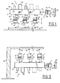
- the components 1a, 1b, 1c .... of an apparatus such as an optical bench 1 for example, are mounted on a chassis 3 formed in one piece and which is supported in an isostatic manner by a system according to the invention.
- chassis 3 is shown diagrammatically in the form of a substantially rectangular parallelepiped on which the two upper 3a and lower 3b faces, the two longitudinal side faces 3c and the two end faces 3d can be distinguished.
- the components 1a, 1b, 1c .... of the optical bench 1 are mounted on the upper face 3a of the chassis 3, this chassis 3 resting by its lower face 3b on the system according to the invention
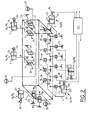
- the system notably comprises a set of substantially vertical supports such as jacks 7, of the hydraulic type for example.
- Each cylinder 7 can be constituted, in a manner known per se, by a hollow body 9 in which is slidably mounted a piston 10 which thus divides the internal volume of the body 9 into two chambers A and B with variable volume.
- the piston 10 On the side of chamber B, the piston 10 is extended by a piston rod 12 the free end of which projects outside the jack 7.
- each jack 7 is mounted articulated at 15 on a fixed base 17 which rests on the ground, while the free end of the piston rod 12 is mounted articulated at 19 on the underside 3b of the chassis 3.
- the joints 15 and 19 are ball joints, for example.
- the frame 3 is supported by twelve jacks 7 (FIG. 2), the number and the position of these jacks 7 being determined as a function of the dimensions and the mass of the frame 3, so that the latter is supported without excessive deformation and mechanical stress and that its mass is regularly distributed or balanced over all the support points 19 of the system and avoiding any hyperstatism.
- the support system is of the active isostatic type to allow repositioning of the chassis 3 according to several degrees of freedom.
- the twelve jacks 7 are divided into three active hydraulic networks R1, R2 and R3 which each include four jacks 7.
- the four jacks 7 of the hydraulic network R1 are controlled from a metering unit U1 which simultaneously supplies fluid to the lower chambers A of the jacks 7, while the upper chambers B are exhausted by a valve 21.
- the chambers A of cylinders 7 are connected by flexible tubes t to the unit U1. It is the same for the supply of the cylinders of the hydraulic networks R2 and R3 which are supplied from metering units U2 and U3, respectively.
- Each metering unit U1, U2 and U3 is for example constituted by a jack 23 which comprises a chamber C of variable volume filled with a fluid which is conveyed in the pipes t of the hydraulic networks R1 to R3 by a piston 25 movable in translation and controlled by a central unit UC which is connected to the metering units U1, U2 and U3.
- the system also includes lateral supports which are constituted by jacks 7.
- the body 9 of each jack is mounted articulated at 27 on an upright vertical 29 which is or is not integral with the base 17, while the free end of the piston rod 12 is mounted articulated at 31 on a longitudinal face 3c of the chassis 3.
- the articulations 27 and 31 are ball joints for example.
- the number of lateral supports is four, but this number and the position of the jacks 7 vary in particular depending on the distribution of the mass and the length of the chassis 3.
- the four jacks 7 are divided into two networks R4 and R5 each comprising two jacks 7.
- the two networks R4 and R5 are supplied from two metering units U4 and U5, respectively.
- the two chambers A of each jack 7 communicate with the associated metering unit by flexible tubes t , while the chambers B communicate with a hydraulic accumulator.
- the system also comprises end supports which are also constituted by jacks 7.
- the end supports are constituted by two jacks 7 which are supplied by an active hydraulic network R6 to ensure control positioning the chassis 3 according to an additional degree of freedom.
- the two jacks 7 are mounted articulated on the chassis 3 and on a vertical upright (not shown), in a similar manner to the jacks 7 of the lateral supports.
- all dosing units U1 to U6 are controlled from a unit central CPU.
- the piston rod 26 of the cylinder 23 of each metering unit is controlled in translation from a screw-nut system 34 which converts the rotation of the output shaft of a motor into a movement of translation.
- An engine is then fitted to each dosing unit and this engine is controlled from the central processing unit UC.
- position sensors are distributed along the chassis 3 to measure the position of the optical bench 1 relative to a positioning reference frame, the measurements of these sensors being transmitted to the central unit UC.
- the chassis 3 is supported in an isostatic manner with in addition the possibility of repositioning the chassis 3 according to the six degrees of freedom by means of the active hydraulic networks R1 to R6 .
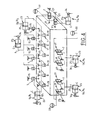
- the chassis 3 is this time suspended from the support system.
- the components 1a, 1b and 1c of the optical bench 1 are for example fixed on the underside 3b of the frame 3, while the jacks 7 of the vertical supports are mounted articulated between a fixed structure 35 such as a gantry for example, and the upper face 3a of the chassis 3.
- FIG. 5 and 6 is a variant of the first embodiment illustrated in Figures 1 and 2, the chassis 3 being substantially square in shape for example.
- the lateral and end supports of the system are constituted by articulated links 40.
- Each link 40 is articulated at 42 to the chassis 3 on the one hand, and at 44 to a fixed structure 29.
- the chassis 3 is placed on the vertical supports constituted by jacks 7 arranged in the same manner as that illustrated in FIGS. 1 and 2.
- the system supports the chassis 3 in an isostatic manner via the vertical supports, with the possibility of controlling the positioning of the chassis 3 according to three degrees of freedom which are defined from three active hydraulic networks R1, R2 and R3.
- the jacks 7 of the vertical supports are nine in number and are distributed in three active hydraulic networks R1, R2 and R3 which each comprise three jacks 7.
- the jacks 7 of the network R1 define three support points P11, P12 and P13, those of the network R2 define three support points P21, P22 and P23, while those of the network R3 define three support points P31, P32 and P33.
- FIGS 7 and 8 illustrate another embodiment according to the invention. This embodiment can be used to suspend the chassis 3 when it is narrow, high and extends over a great length for example.
- the vertical supports consist of a set of jacks 7 which are distributed along two active hydraulic networks R1 and R2, the lateral supports are constituted by a set of jacks 7 which are distributed along three hydraulic networks R3, R4 and R5, while the end supports are constituted by jacks connected to a network active hydraulic R6. It is thus possible to control the positioning of the chassis 3 according to the six degrees of freedom.
- the end supports can consist of articulated links 40, that is to say that the control of the positioning of the chassis can then only be done according to five degrees of freedom.
- the chassis 3 can be constituted by a plate of a certain thickness or by a beam lattice, the choice depending on the nature of the optical bench to be supported.
- the invention has been described by taking the example of an optical bench but this bench could just as easily be a laser chain.
- the system can therefore be used to support any measuring equipment.
Landscapes
- Engineering & Computer Science (AREA)
- General Engineering & Computer Science (AREA)
- Mechanical Engineering (AREA)
- Chemical & Material Sciences (AREA)
- Analytical Chemistry (AREA)
- Physics & Mathematics (AREA)
- General Physics & Mathematics (AREA)
- Telescopes (AREA)
Applications Claiming Priority (2)
| Application Number | Priority Date | Filing Date | Title |
|---|---|---|---|
| FR9605776A FR2748546B1 (fr) | 1996-05-09 | 1996-05-09 | Systeme pour supporter un appareillage de grandes dimensions en particulier un banc optique |
| FR9605776 | 1996-05-09 |
Publications (2)
| Publication Number | Publication Date |
|---|---|
| EP0806601A2 true EP0806601A2 (de) | 1997-11-12 |
| EP0806601A3 EP0806601A3 (de) | 1999-12-08 |
Family
ID=9491970
Family Applications (1)
| Application Number | Title | Priority Date | Filing Date |
|---|---|---|---|
| EP97400963A Withdrawn EP0806601A3 (de) | 1996-05-09 | 1997-04-29 | Trageinrichtung für eine Vorrichtung grosser Abmessungen, insbesondere eine optische Bank |
Country Status (2)
| Country | Link |
|---|---|
| EP (1) | EP0806601A3 (de) |
| FR (1) | FR2748546B1 (de) |
Cited By (1)
| Publication number | Priority date | Publication date | Assignee | Title |
|---|---|---|---|---|
| CN109459223A (zh) * | 2018-12-10 | 2019-03-12 | 辽宁科技大学 | 一种液压支架模型试验的加载装置及试验方法 |
Family Cites Families (4)
| Publication number | Priority date | Publication date | Assignee | Title |
|---|---|---|---|---|
| US3288421A (en) * | 1965-03-29 | 1966-11-29 | Everett R Peterson | Movable and rotatable top |
| DE3480664D1 (de) * | 1983-08-30 | 1990-01-11 | Perkin Elmer Corp | Anordnung zum nivellieren einer oberflaeche. |
| DE3827240A1 (de) * | 1988-08-11 | 1990-02-15 | Renk Tacke Gmbh | Daempfungs- und positioniereinrichtung fuer getriebe |
| DE4128669A1 (de) * | 1991-08-29 | 1993-03-04 | Zeiss Carl Jena Gmbh | Dreidimensional verstellbare deckenaufhaengung fuer operationsmikroskope |
-
1996
- 1996-05-09 FR FR9605776A patent/FR2748546B1/fr not_active Expired - Fee Related
-
1997
- 1997-04-29 EP EP97400963A patent/EP0806601A3/de not_active Withdrawn
Cited By (1)
| Publication number | Priority date | Publication date | Assignee | Title |
|---|---|---|---|---|
| CN109459223A (zh) * | 2018-12-10 | 2019-03-12 | 辽宁科技大学 | 一种液压支架模型试验的加载装置及试验方法 |
Also Published As
| Publication number | Publication date |
|---|---|
| FR2748546B1 (fr) | 1998-08-14 |
| EP0806601A3 (de) | 1999-12-08 |
| FR2748546A1 (fr) | 1997-11-14 |
Similar Documents
| Publication | Publication Date | Title |
|---|---|---|
| EP1049950B1 (de) | Vorrichtung zur montage und lagekorrektur eines elementes, wie eines spiegels von einem weltraumteleskop | |
| CA2912163C (fr) | Banc d'essai en fatigue oligocyclique ou en fatigue oligocyclique et polycyclique | |
| FR2635500A1 (fr) | Dispositif universel de montage et de mise en marche pour le lancement d'un vehicule spatial | |
| EP0113145B1 (de) | Verbindungsglied mit mehreren Freiheitsgraden | |
| FR3020977A1 (fr) | Nacelle pour robot parallele destine a agir sur un objet | |
| FR2958695A1 (fr) | Verin apte a etre utilise dans une tourelle hexapode et tourelle hexapode comprenant le verin | |
| EP0479653B1 (de) | Montagevorrichtung für eine parallel zum Chassis eines Fahrzeuges ausfahrbare Ladebordwand | |
| EP0491613B1 (de) | Handhabungsgerät zum Bewegen eines Gegenstandes in Raum, z.B. parallel mit sichselbst | |
| FR2533288A1 (fr) | Dispositif compose de deux ensembles montes pivotants l'un par rapport a l'autre tel qu'un chassis pour le moulage d'elements en beton, un heliostat ou analogue | |
| EP1402992A1 (de) | Vorrichtung mit höher Präzision zum Vorgeben oder zum Messen einer Position oder Kraft | |
| EP0968450B1 (de) | Mikrometrische positionierungsvorrichtung einer halterung eines optischen elements mit sechs freiheitsgraden | |
| EP0806601A2 (de) | Trageinrichtung für eine Vorrichtung grosser Abmessungen, insbesondere eine optische Bank | |
| FR2930936A1 (fr) | Systeme de regulation d'un portique a double moyen d'entrainement | |
| FR2681665A1 (fr) | Procede d'alignement de plusieurs groupes d'une machine disposes en serie. | |
| EP1309429B1 (de) | Plattform mit filtration von schwingungen für eine robotisierte anlage zum bearbeiten von kraftfahrzeugkästen | |
| FR2714855A1 (fr) | Vibreur à faible encombrement et à grande force de vibration, et machines équipées de ce vibreur. | |
| WO2013121130A1 (fr) | Dispositif et système d'alignement et de maintien en position de poutres | |
| FR2638587A1 (fr) | Dispositif demontable de support d'un resonateur piezoelectrique a l'interieur d'un boitier | |
| FR2698293A1 (fr) | Vibreur à masses rotatives à balourd réglable et supprimable, et machines équipées de ce vibreur. | |
| FR2556463A1 (fr) | Extensometre permettant de mesurer directement et simultanement la deformation axiale et la distorsion d'une eprouvette | |
| FR2773415A1 (fr) | Dispositif de calage transversal d'assemblages combustibles nucleaires a l'interieur d'emballages de transport | |
| FR2715456A1 (fr) | Dispositif de support ponctuel. | |
| FR3147628A1 (fr) | procédé et dispositif de détermination de charge pour plate-forme de travail de nacelle élévatrice | |
| FR2631377A1 (fr) | Dispositif de secours ou a usage industriel, susceptible d'etre installe sur un chassis de vehicule et engin equipe d'un tel dispositif | |
| EP4688640A1 (de) | Verfahren und vorrichtung zur bestimmung der last einer hubarbeitsbühne |
Legal Events
| Date | Code | Title | Description |
|---|---|---|---|
| PUAI | Public reference made under article 153(3) epc to a published international application that has entered the european phase |
Free format text: ORIGINAL CODE: 0009012 |
|
| AK | Designated contracting states |
Kind code of ref document: A2 Designated state(s): CH DE GB IT LI SE |
|
| PUAL | Search report despatched |
Free format text: ORIGINAL CODE: 0009013 |
|
| AK | Designated contracting states |
Kind code of ref document: A3 Designated state(s): CH DE GB IT LI SE |
|
| STAA | Information on the status of an ep patent application or granted ep patent |
Free format text: STATUS: THE APPLICATION HAS BEEN WITHDRAWN |
|
| 18W | Application withdrawn |
Withdrawal date: 20000413 |