EP0112892B1 - A plant for processing by cutting material with the aid of a laser beam - Google Patents
A plant for processing by cutting material with the aid of a laser beam Download PDFInfo
- Publication number
- EP0112892B1 EP0112892B1 EP83902311A EP83902311A EP0112892B1 EP 0112892 B1 EP0112892 B1 EP 0112892B1 EP 83902311 A EP83902311 A EP 83902311A EP 83902311 A EP83902311 A EP 83902311A EP 0112892 B1 EP0112892 B1 EP 0112892B1
- Authority
- EP
- European Patent Office
- Prior art keywords
- tube
- slide
- holder
- plant
- mirror
- Prior art date
- Legal status (The legal status is an assumption and is not a legal conclusion. Google has not performed a legal analysis and makes no representation as to the accuracy of the status listed.)
- Expired
Links
- 239000000463 material Substances 0.000 title claims description 15
- 239000000779 smoke Substances 0.000 claims description 2
- 238000012216 screening Methods 0.000 claims 1
- 238000003698 laser cutting Methods 0.000 abstract description 2
- 239000007789 gas Substances 0.000 description 8
- 238000006073 displacement reaction Methods 0.000 description 3
- 239000002245 particle Substances 0.000 description 3
- 239000000567 combustion gas Substances 0.000 description 2
- 238000001816 cooling Methods 0.000 description 2
- 239000000110 cooling liquid Substances 0.000 description 2
- 238000005516 engineering process Methods 0.000 description 2
- 239000004744 fabric Substances 0.000 description 2
- 239000002184 metal Substances 0.000 description 2
- 238000007789 sealing Methods 0.000 description 2
- 208000020564 Eye injury Diseases 0.000 description 1
- 229920005372 Plexiglas® Polymers 0.000 description 1
- 230000001427 coherent effect Effects 0.000 description 1
- 239000002826 coolant Substances 0.000 description 1
- 239000012809 cooling fluid Substances 0.000 description 1
- 230000006378 damage Effects 0.000 description 1
- 239000000428 dust Substances 0.000 description 1
- 239000000835 fiber Substances 0.000 description 1
- 239000002985 plastic film Substances 0.000 description 1
- 230000001681 protective effect Effects 0.000 description 1
- 239000002699 waste material Substances 0.000 description 1
Images

Classifications
-
- B—PERFORMING OPERATIONS; TRANSPORTING
- B23—MACHINE TOOLS; METAL-WORKING NOT OTHERWISE PROVIDED FOR
- B23K—SOLDERING OR UNSOLDERING; WELDING; CLADDING OR PLATING BY SOLDERING OR WELDING; CUTTING BY APPLYING HEAT LOCALLY, e.g. FLAME CUTTING; WORKING BY LASER BEAM
- B23K26/00—Working by laser beam, e.g. welding, cutting or boring
- B23K26/08—Devices involving relative movement between laser beam and workpiece
- B23K26/10—Devices involving relative movement between laser beam and workpiece using a fixed support, i.e. involving moving the laser beam
Definitions
- the invention relates to a plant of the kind disclosed in the preamble to the appended claim 1.
- Laser technology is well suited for cutting, e.g. cloth, plastic sheets, plate or fibre particle boards, since, inter alia, the cutting laser beam can be made very narrow and energy-intensive, whereby material waste will be very small.
- a work table for the material.
- a first slide can be displaceably arranged along the table and extend transverse the table.
- a second slide can be displaceably arranged on the first slide for displacement along the first slide, i.e. across the table.
- controlled displacement of the two slides the second slide can be caused to find an arbitrary point on the table.
- Such controlled displacement can be provided by conventional technology with the aid of numerical control, i.e. the driving means of the slides are controlled with the aid of a programmed computer.
- the laser unit can have a mass of about 400 kg, and since in plants of the kind in question it is desirable to have a cutting speed which is as high as possible in the plane of the table, it will be understood that the plant is subjected to large stresses due to the mass of the laser unit when the direction and rate of travel of the second slide are changed. For reasons of precision and strength, such a known plant must therefore be implemented very robustly and it will therefore be very expensive.
- the cutting speed can hardly be made larger than some few m/min even so.
- the laser unit has therefore been placed stationary relative the table, the "weightless" laser beam being deflected instead to desired points on the table with the aid of deflection mirrors, the beam path then being enclosed in a telescopic-type tube system, cf SE 347 680.
- the tube system serves the purpose of preventing the operator from being injured by the laser beam, it thus preventing direct contact with the beam and constitutes a dazzle shield so that eye injuries are avoided.
- the system can serve to prevent dirtying the mirrors which are placed in the tube system.
- Telescopic tube systems have been found to be substantially unusable, at least with relatively large cutting table surfaces, e.g. 2 x 3 m, and cutting speeds in the order of magnitude of 1 m/s.
- the second slide In order to be able to operate this mirror without vibration, which is particularly difficult since the sections of the first telescopic tube tend to hook into each other, the second slide would need to be provided with a support carrying the mirror in question at a distance from the table corresponding to a telescopic section length. In turn, this results in further weight problems.
- One object with the invention is to remove the mentioned drawbacks in known laser cutting plants which have a tube system through which the laser beam path extends.
- the invention relates to a plant of the implementation apparent from the following main claim.
- Each tube is suitably assigned a pair of elastic lips in mutual resilient engagement along the axial slit in the tube to cover the slit.
- the part of the mirror holder extending through the slit is suitably cuneiform in order to part the lips.
- the second mirror holder which is rigidly mounted in relation to the second slide for deflecting the laser beam to the table, is suitably connected to a third tube, which contains a focusing lens for the beam at its end remote from the second holder.
- the first tube is suitably closed off at its end remote from the laser unit.
- the second tube is suitably closed off at its end remote from the first mirror holder.
- the third tube suitably has an opening for the departing beam at its end which is remote from the second mirror holder. It is thus possible to introduce a pure gas into the first tube in the vicinity of the laser unit, and this pure gas can then flow through the first tube, the second tube and out through the third tube, thus preventing combustion gases or particles from the processed material coming into contact with the deflection mirrors or coming into the laser beam path.
- the mirror holder is suitably implemented such that gas can freely pass the holder in the tube, thus substantially avoiding local pressure variations in the tube as a result of displacing the holder.
- the pure gas can of course be flushed through each tube separately.
- the laser unit may include a CO 2 laser, for example, which sends coherent light having a wavelength somewhat greater than ⁇ l m.
- Laser power e.g. in cutting cloth, may attain some hundreds of watts, the beam having a diameter of say 6-15 mm.
- Plexiglas@ may be used as the tube material for this wavelength, but it should be quite clear that almost any kind of material may be used for the tubes, since they are primarily intended to serve as touch protection.
- the mirror holders may include a pipe coil through which a cooling fluid, e.g. a cooling liquid, can be passed for cooling the mirror.
- a cooling fluid e.g. a cooling liquid
- the pure gas can be utilized as coolant for the mirrors.
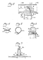
- FIGs 1 and 2 there is shown a work table 7 provided at its sides with guide rails 12 and 13 for a first slide 8, which has grooves 18 and 19 on its underside for the rails 12 and 13, respectively.
- the first slide 8 extends over the entire width of the table 7, and has on its upper side a pair of guide rails 10 and 11 for a second slide 9, which is guided by a pair of unillustrated guide grooves for travel along the rails 10 and 11.
- the table 7 is carried by a frame denoted by the numeral 20.
- a laser unit 1 is illustrated in Figure 1 and is disposed stationary in relation to the table 7. As will be seen from Figures 1 and 2, the laser unit 1 is adapted to send a beam 50 extending parallel to the surface of the table 7, at one side of the table and at the side of, or above the second slide 9.
- the beam 50 extends coaxially through a first tube 2, which is disposed stationary in relation to the table 7.
- the tube 2 has an axial slit on the right-hand side of the tube 2 in the plane of the Figure in Figure 1.
- tube 2 there is a mirror holder with mirror, generally denoted by Illa.
- the mirror deflects the beam 50 so that it extends out through the slit in the tube 2 and coaxially into a connecting tube 4, which is mounted on the first slide 8 with the aid of holders 17.
- the tube 4 also has an axial slit, disposed on its underside in Figure 1.
- a further mirror holder and mirror generally denoted by Illb is disposed in the second tube 4 such that the beam 50 can be deflected downwards through the axial slit of the tube and coaxially into a third tube 14 containing a focusing lens 16 for the beam, and which at its lower portion has an opening 15 for the focused laser beam.
- the opening 15 is arranged close to the material laid up on table 7 for cutting.
- the tube 2 is closed by a cover 3, and in a corresponding way the tube 4 is closed by a cover 40 at its remote end.
- the slit 21 of tubes 2, 4 is covered by a pair of elastic lips 31, which are attached to the tube and are in mutual resilient engagement opposite the slit 21.
- the mirror holder denoted by llla and Illb in Figures 1 and 2 is more closely illustrated in Figures 3, 4 and 6.
- the mirror holder III includes a head 23 on which a mirror 22 is adjustably mounted, the mirror being generally kept at an angle of about 45° to the incident beam 50, such that the mirror deflects the beam 50 out through the tube slit 21.
- the mirror holder head 23 is carried by a shank portion 24, the width of which is suited to the width of the slit 21 for travel along the slit.
- the edges of the shank portion 24 are given a plough shape for easily parting the lips 31.
- the shank portion 24 is carried by a foot part 37 tightly sealing against the connecting tube 4, (14).
- An opening 25 is arranged in the shank portion and foot part of the mirror holder to allow free passage for the deflected beam 50 and possibly a gas introduced into the tubes.
- a ducting coil 26 is arranged in the mirror holder, e.g. for carrying cooling liquid for cooling the mirror 22.
- the shank portion 24 of the mirror holder will move along the slit 21 of the tube 2 and by reason of its plough shape move the lips 31 apart, said lips either sealing against each other or against the long sides of the shank portion 22, due to their elasticity.
- the laser beam will therefore extend entirely enclosed from the unit 1 to the opening 15 of the third tube 14 irrespective of the movements of the slides 8, 9 and thereby the movements of the tubes 4, 14 relative the unit, and the enclosure is so complete that an operator cannot unintentionally come into contact with the laser beam 50.
- the enclosure provided by the tubes, lips and mirror holders is further such that a protective gas can be introduced, e.g.
- the table 7 can be made from expanded metal, honeycomb material or the like, and a vaccum source may be connected to the underside of the table. If the table is made from expanded metal or the like, the risk of damage to the table from the laser beam is reduced, and material debris can fall down through the interstices in the table surface. If a vaccum source is connected to such a table, both particles of material and combustion gases may be easily removed.
- the opening of the tube 14 is surrounded by a suction box 41 having an annular slit 42.
- the box 41 is evacuated via a conduit 43, the evacuation of smoke etc. being enabled via the slit 42 and conduit 43.
Landscapes
- Physics & Mathematics (AREA)
- Optics & Photonics (AREA)
- Engineering & Computer Science (AREA)
- Plasma & Fusion (AREA)
- Mechanical Engineering (AREA)
- Laser Beam Processing (AREA)
Priority Applications (1)
| Application Number | Priority Date | Filing Date | Title |
|---|---|---|---|
| AT83902311T ATE19978T1 (de) | 1982-07-05 | 1983-07-04 | Materialschneidevorrichtung mit laserstrahl. |
Applications Claiming Priority (2)
| Application Number | Priority Date | Filing Date | Title |
|---|---|---|---|
| SE8204154A SE430390B (sv) | 1982-07-05 | 1982-07-05 | Anleggning for skerande bearbetning av material medelst en laserstrale |
| SE8204154 | 1982-07-05 |
Publications (2)
| Publication Number | Publication Date |
|---|---|
| EP0112892A1 EP0112892A1 (en) | 1984-07-11 |
| EP0112892B1 true EP0112892B1 (en) | 1986-05-28 |
Family
ID=20347287
Family Applications (1)
| Application Number | Title | Priority Date | Filing Date |
|---|---|---|---|
| EP83902311A Expired EP0112892B1 (en) | 1982-07-05 | 1983-07-04 | A plant for processing by cutting material with the aid of a laser beam |
Country Status (8)
| Country | Link |
|---|---|
| US (1) | US4582977A (da) |
| EP (1) | EP0112892B1 (da) |
| AU (1) | AU566364B2 (da) |
| DE (1) | DE3363733D1 (da) |
| DK (1) | DK150405C (da) |
| FI (1) | FI76270C (da) |
| SE (1) | SE430390B (da) |
| WO (1) | WO1984000123A1 (da) |
Families Citing this family (2)
| Publication number | Priority date | Publication date | Assignee | Title |
|---|---|---|---|---|
| IT1211558B (it) * | 1987-11-26 | 1989-11-03 | Bruno Bisiach | Robot a fascio laser per taglio e saldatura |
| WO2009009187A1 (en) * | 2007-06-15 | 2009-01-15 | Johnson Controls - Saft Advanced Power Solutions Llc | Laser cutting system |
Family Cites Families (7)
| Publication number | Priority date | Publication date | Assignee | Title |
|---|---|---|---|---|
| US31042A (en) * | 1861-01-01 | Improvement in knitting-machines | ||
| US3582466A (en) * | 1968-07-09 | 1971-06-01 | Harrison P Quirk | Paper web slitter apparatus including a laser and light transmissive structure |
| DE2326049A1 (de) * | 1973-05-22 | 1974-12-12 | Guenter Stumpf | Vorrichtung zum schneiden mehrerer aufeinanderfolgender folien oder stofflagen |
| US3866398A (en) * | 1973-12-20 | 1975-02-18 | Texas Instruments Inc | In-situ gas-phase reaction for removal of laser-scribe debris |
| DE2643981A1 (de) * | 1976-09-29 | 1978-03-30 | Texas Instruments Deutschland | Vorrichtung zum absaugen des beim ritzen von halbleiterscheiben mittels laserstrahlen entstehenden staubs |
| USRE31042E (en) | 1978-08-29 | 1982-09-28 | Houdaille Industries, Inc. | Laser cutting head attachment for punch presses |
| US4223201A (en) * | 1978-12-14 | 1980-09-16 | United Technologies Corporation | Laser welding apparatus for shipyard panel shops |
-
1982
- 1982-07-05 SE SE8204154A patent/SE430390B/sv not_active IP Right Cessation
-
1983
- 1983-07-04 AU AU17762/83A patent/AU566364B2/en not_active Ceased
- 1983-07-04 EP EP83902311A patent/EP0112892B1/en not_active Expired
- 1983-07-04 US US06/598,316 patent/US4582977A/en not_active Expired - Fee Related
- 1983-07-04 WO PCT/SE1983/000271 patent/WO1984000123A1/en not_active Ceased
- 1983-07-04 DE DE8383902311T patent/DE3363733D1/de not_active Expired
-
1984
- 1984-03-02 DK DK151384A patent/DK150405C/da not_active IP Right Cessation
- 1984-03-05 FI FI840864A patent/FI76270C/fi not_active IP Right Cessation
Also Published As
| Publication number | Publication date |
|---|---|
| DE3363733D1 (en) | 1986-07-03 |
| FI76270C (fi) | 1988-10-10 |
| DK151384A (da) | 1984-03-02 |
| US4582977A (en) | 1986-04-15 |
| FI840864A0 (fi) | 1984-03-05 |
| EP0112892A1 (en) | 1984-07-11 |
| WO1984000123A1 (en) | 1984-01-19 |
| DK150405B (da) | 1987-02-23 |
| DK150405C (da) | 1988-01-25 |
| AU1776283A (en) | 1984-01-26 |
| AU566364B2 (en) | 1987-10-15 |
| FI76270B (fi) | 1988-06-30 |
| DK151384D0 (da) | 1984-03-02 |
| SE8204154D0 (sv) | 1982-07-05 |
| FI840864L (fi) | 1984-03-05 |
| SE430390B (sv) | 1983-11-14 |
Similar Documents
| Publication | Publication Date | Title |
|---|---|---|
| US5660748A (en) | Laser beam machine with an optical fiber cable | |
| CA1206210A (en) | Light pattern projector especially for welding | |
| KR102099996B1 (ko) | 클램핑 클로에 대해 이동될 수 있는 레이저 가공 헤드를 갖는 레이저 가공 장치 | |
| US6140606A (en) | Laser cutting system | |
| US6600131B2 (en) | Laser cutting system | |
| GB1360380A (en) | Laser beam apparatus | |
| EP2301706A2 (en) | Laser machining machine | |
| EP0206027A2 (en) | End-of-arm tooling carousel apparatus for use with a robot | |
| CN107717227B (zh) | 一种激光窄间隙焊接头 | |
| US6545249B2 (en) | Laser cutting system | |
| TWI445588B (zh) | 具掃瞄透鏡後偏轉之雷射微加工系統 | |
| US4761534A (en) | Laser apparatus | |
| EP1539419A1 (en) | Laser welding method and apparatus for suppressing plasma | |
| US6300592B1 (en) | Laser cutting system | |
| US6588738B1 (en) | Laser cutting system | |
| EP0112892B1 (en) | A plant for processing by cutting material with the aid of a laser beam | |
| US3742183A (en) | Optical element protection in laser apparatus | |
| GB1215714A (en) | Improvements relating to thermal cutting apparatus | |
| RU96100472A (ru) | Устройство для лазерной наплавки | |
| JPH10137970A (ja) | 熱加工装置およびその装置に用いる加工ヘッド | |
| GB1334772A (en) | Laser device having means for protecting the human body against harmful rays | |
| Edler et al. | New nozzle concept for cutting with high power lasers | |
| JPH05237682A (ja) | レーザ光集光装置 | |
| US6291795B1 (en) | Unfocused laser beam delivery system | |
| CA2380063C (en) | Laser cutting system |
Legal Events
| Date | Code | Title | Description |
|---|---|---|---|
| PUAI | Public reference made under article 153(3) epc to a published international application that has entered the european phase |
Free format text: ORIGINAL CODE: 0009012 |
|
| 17P | Request for examination filed |
Effective date: 19840306 |
|
| AK | Designated contracting states |
Designated state(s): AT BE CH DE FR GB LI NL |
|
| GRAA | (expected) grant |
Free format text: ORIGINAL CODE: 0009210 |
|
| AK | Designated contracting states |
Kind code of ref document: B1 Designated state(s): AT BE CH DE FR GB LI NL |
|
| PG25 | Lapsed in a contracting state [announced via postgrant information from national office to epo] |
Ref country code: NL Effective date: 19860528 Ref country code: LI Effective date: 19860528 Ref country code: CH Effective date: 19860528 Ref country code: AT Effective date: 19860528 |
|
| REF | Corresponds to: |
Ref document number: 19978 Country of ref document: AT Date of ref document: 19860615 Kind code of ref document: T |
|
| REF | Corresponds to: |
Ref document number: 3363733 Country of ref document: DE Date of ref document: 19860703 |
|
| ET | Fr: translation filed | ||
| REG | Reference to a national code |
Ref country code: CH Ref legal event code: PL |
|
| NLV1 | Nl: lapsed or annulled due to failure to fulfill the requirements of art. 29p and 29m of the patents act | ||
| PLBE | No opposition filed within time limit |
Free format text: ORIGINAL CODE: 0009261 |
|
| STAA | Information on the status of an ep patent application or granted ep patent |
Free format text: STATUS: NO OPPOSITION FILED WITHIN TIME LIMIT |
|
| 26N | No opposition filed | ||
| PGFP | Annual fee paid to national office [announced via postgrant information from national office to epo] |
Ref country code: GB Payment date: 19900622 Year of fee payment: 8 Ref country code: FR Payment date: 19900622 Year of fee payment: 8 |
|
| PGFP | Annual fee paid to national office [announced via postgrant information from national office to epo] |
Ref country code: BE Payment date: 19900629 Year of fee payment: 8 |
|
| PGFP | Annual fee paid to national office [announced via postgrant information from national office to epo] |
Ref country code: DE Payment date: 19900823 Year of fee payment: 8 |
|
| PG25 | Lapsed in a contracting state [announced via postgrant information from national office to epo] |
Ref country code: GB Effective date: 19910704 |
|
| PG25 | Lapsed in a contracting state [announced via postgrant information from national office to epo] |
Ref country code: BE Effective date: 19910731 |
|
| BERE | Be: lapsed |
Owner name: INGENJORSFIRMA G. KNUTSSON A.B. Effective date: 19910731 |
|
| GBPC | Gb: european patent ceased through non-payment of renewal fee | ||
| PG25 | Lapsed in a contracting state [announced via postgrant information from national office to epo] |
Ref country code: FR Effective date: 19920331 |
|
| PG25 | Lapsed in a contracting state [announced via postgrant information from national office to epo] |
Ref country code: DE Effective date: 19920401 |
|
| REG | Reference to a national code |
Ref country code: FR Ref legal event code: ST |