EP0112316B1 - Expansion body - Google Patents
Expansion body Download PDFInfo
- Publication number
- EP0112316B1 EP0112316B1 EP83850337A EP83850337A EP0112316B1 EP 0112316 B1 EP0112316 B1 EP 0112316B1 EP 83850337 A EP83850337 A EP 83850337A EP 83850337 A EP83850337 A EP 83850337A EP 0112316 B1 EP0112316 B1 EP 0112316B1
- Authority
- EP
- European Patent Office
- Prior art keywords
- casing
- socket
- expansion body
- body according
- folds
- Prior art date
- Legal status (The legal status is an assumption and is not a legal conclusion. Google has not performed a legal analysis and makes no representation as to the accuracy of the status listed.)
- Expired
Links
- 239000012530 fluid Substances 0.000 claims abstract description 7
- 238000010276 construction Methods 0.000 claims abstract description 3
- 238000007789 sealing Methods 0.000 claims description 8
- 238000003825 pressing Methods 0.000 claims description 4
- 239000011345 viscous material Substances 0.000 claims description 2
- 230000037431 insertion Effects 0.000 abstract description 2
- 238000003780 insertion Methods 0.000 abstract description 2
- 239000004567 concrete Substances 0.000 description 11
- 238000003466 welding Methods 0.000 description 5
- 239000003795 chemical substances by application Substances 0.000 description 4
- 238000004519 manufacturing process Methods 0.000 description 4
- 239000010426 asphalt Substances 0.000 description 3
- XEEYBQQBJWHFJM-UHFFFAOYSA-N Iron Chemical compound [Fe] XEEYBQQBJWHFJM-UHFFFAOYSA-N 0.000 description 2
- 230000015572 biosynthetic process Effects 0.000 description 2
- XLYOFNOQVPJJNP-UHFFFAOYSA-N water Substances O XLYOFNOQVPJJNP-UHFFFAOYSA-N 0.000 description 2
- 229910000831 Steel Inorganic materials 0.000 description 1
- 239000003570 air Substances 0.000 description 1
- 238000005336 cracking Methods 0.000 description 1
- 230000007423 decrease Effects 0.000 description 1
- 230000003247 decreasing effect Effects 0.000 description 1
- 238000005553 drilling Methods 0.000 description 1
- 238000011065 in-situ storage Methods 0.000 description 1
- 229910052742 iron Inorganic materials 0.000 description 1
- 239000002184 metal Substances 0.000 description 1
- 229910052751 metal Inorganic materials 0.000 description 1
- 239000004033 plastic Substances 0.000 description 1
- 229920003023 plastic Polymers 0.000 description 1
- 230000003014 reinforcing effect Effects 0.000 description 1
- 230000000717 retained effect Effects 0.000 description 1
- 238000005096 rolling process Methods 0.000 description 1
- 239000010959 steel Substances 0.000 description 1
- 239000000126 substance Substances 0.000 description 1
Images


Classifications
-
- E—FIXED CONSTRUCTIONS
- E02—HYDRAULIC ENGINEERING; FOUNDATIONS; SOIL SHIFTING
- E02D—FOUNDATIONS; EXCAVATIONS; EMBANKMENTS; UNDERGROUND OR UNDERWATER STRUCTURES
- E02D5/00—Bulkheads, piles, or other structural elements specially adapted to foundation engineering
- E02D5/74—Means for anchoring structural elements or bulkheads
- E02D5/80—Ground anchors
- E02D5/805—Ground anchors with deformable anchoring members
-
- E—FIXED CONSTRUCTIONS
- E02—HYDRAULIC ENGINEERING; FOUNDATIONS; SOIL SHIFTING
- E02D—FOUNDATIONS; EXCAVATIONS; EMBANKMENTS; UNDERGROUND OR UNDERWATER STRUCTURES
- E02D5/00—Bulkheads, piles, or other structural elements specially adapted to foundation engineering
- E02D5/22—Piles
- E02D5/54—Piles with prefabricated supports or anchoring parts; Anchoring piles
Definitions
- This invention relates to an expansion body for constructions located in the earth including a folded elongated casing and a first and a second closure arranged at the upper and lower end respectively of the casing, said casing and closures defining an internal closed space connectable to a source of pressurized fluid for the expansion of the body by pressing out the folds of the casing.
- Expansion bodies of the kind mentioned above have been proposed for in situ piles and especially as an expanded foot of these.
- the casing is first inserted into the ground and then filled with pressurized water and concrete for pressing out the folds thereof thus giving the pile its final shape.
- closures A problem related to the expansion bodies of that kind has been the arrangement of the end closures.
- said closures must be designed for sealing the end parts of the casing as well as for enabling the fold to unfold gradually from the ends without causing cracking tensions in the casing.
- the closures are shaped like cone-formed endings of the casing with successively decreasing depths of the foldings. Closures like that are, however, in practise impossible to manufacture for a reasonable cost. They are also unsuitable for closely folded casings or when there is a need for larger inlets or tubes leading through the casing.
- An object of the present invention is to provide an expansion body with end closures which eliminate the drawbacks mentioned above. Another object is to provide an end closure which is simple and cheap to manufacture and mount on the ends of the casing.
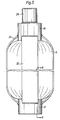
- the expansion body according to Fig. 1 in- eludes a folded casing 11 and end closures 12, 13 arranged at the upper and lower end 14, 15 respectively of the casing 11.
- the casing 11 which is preferably made of sheet metal is folded in zig-zag shape in a way that appears from Figs. 3 and 4 and will be described more in detail later on. In Fig. 1 the folds are only shown schematically.
- Each closure 12, 13 comprises a socket or end cap 16, 17 with a sleeve portion 18, 19 and a bottom portion 20, 21.
- the sleeves 18,19 have preferably a square cross section in order to closely fit within a predrilled hole in the ground to provide for a high degree of expansion.
- the bottom portions 20, 21 in the form of square plates of steel are welded to the sleeves 18, 19 respectively for forming a sealed end.
- Tubular spacing means 22 and 23 respectively are welded to each bottom plate 20, 21 to form part of the sockets 16, 17. They have a rectangular cross section and provide annular spaces 24, 25 between themselves and the sleeves 18, 19.
- the spaces 24, 25 are arranged for receiving the end parts 14 and 15 respectively of the casing 11 and each space 24, 25 comprises two wide parts 26 in which the casing is folded and two narrow parts 27 in which the casing is flat (Fig. 2).
- the upper closure 12 includes a fitting 28 welded to the bottom plate 20 of the socket 16.
- the fitting 28 has an internal thread 29 for connection with a conduit in the form of a pipe, not shown, from an external source of pressurized fluid.
- the fluid for example concrete, water or air is conveyed into the internal space of the casing through a passage 30 in the bottom plate.
- a sealing agent 31 ia arranged to fill up possible openings between the folds and between the end part 14, 15 of the casing and the socket 16,17.
- the sealing agent 31 is preferably some viscous substance as for example asphalt but other substances can also be used for example different plastics.
- connection rods or plates 32 are welded to the sockets 16, 17 for retaining them on the casing ends when the pressurized fluid starts to unfold the casing. It might be sufficient with two rods 32 but it is preferred to have four so that the casing can be protected by them during handling, transportation and insertion in the ground especially when the expansion body is rammed into the ground instead of inserted into a pre-bored hole.
- the rods are adapted to follow the contour of the casing during the expansion of the body, see Fig. 5, and will thus bring the sockets 16, 17 closer to each other as the body shortens due to the expansion.
- the sockets 16, 17 need not be directly affixed to the respective ends of the casings.
- the expansion body is arranged to be the expanded end of a pile or anchor.
- the non-illustrated tube screwed to the fitting 28 forms the stem of the pile or anchor.
- Reinforcing bars can be inserted through the stem and into the expansion body before concrete is forced into the tube to expand the expansion body and form an integral concrete anchor or pile that consists of a stem and a foot.
- expansion bodies can be arranged on the same stem at desired axial intervals.
- the inner sleeves, 22, 23 can then be dispensed with and the stem forming tube can have the same dimension as the sleeves 22, 23.
- the bottom plates 20 can be welded directly to the tube.
- the stem forming tube should then have several big holes into the expansion body for permitting concrete to pass into the expansion body and for providing sufficient concrete bridges between the concrete in the stem and the concrete in the expansion body.
- expansion bodies on pre-formed concrete piles.
- the concrete for expanding the body or bodies can then be injected through a channel in the concrete pile or through conduits outside the pile.
- the pile or anchor with the expansion body or bodies thereon can be inserted into a pre-drilled hole in the ground or they can be forced into the ground.
- the bottom end should be provided with a shoe that can be formed as an arrow point.
- a preferred way of manufacturing the expansion body is to start with rolling an iron sheet to a zig-zag shaped sheet which is cut into smaller sheets of a suitable size.
- Two such sheets, 40, 41, see Fig.3, are laid over each other, face to face, so that the folds 42 of the first sheet 40 fall into the folds 43 of the second sheet 41.
- the sheets 40, 41 form an opening 44, 45 of about the same size as the spacing sleeves 22, 23.
- a die beam in the form of a box girder 46 with the same rectangular cross section as the spacing sleeves 22, 23 is arranged to be located in the opening 44, 45 when the two sheets are inserted in each other, see Fig. 4.
- Fig. 2 is somewhat misleading.
- the spacing sleeve 22 should have the same size in Fig. 2 as in Fig. 1.
- the two longitudinal side edges 47, 48 are welded and the double sheet is pressed in a press, not shown, as indicated by the arrows F.
- the pressing is finished when the folds 42, 43 are in close abutment with each other, as in Fig. 2.
- the beam 46 is withdrawn from the internal space 49 established by the opening 44, 45 and the sleeve 18, 19 are put onto the ends of the casing 11.
- the spacing sleeves 22, 23, to which bottom plates 20, 21 have been welded are inserted into the internal space 49 and the bottom plates 20, 21 are welded to the sleeves 18,19.
- the connecting rods 32 are then attached to the sleeves 18, 19 by welding and the ends of the expansion body are dipped into hot fluent asphalt which fills up and seals possible passages between each end part 14, 15 of the casing 11 and the respective sockets 16, 17 as well as between the folds in the socket.
- the asphalt or other sealing agents penetrates also into the folds between the two sheets 40 and 41.
- the end closures 12, 13 so obtained are adapted for keeping the parts of the casing 11 which are located in the sockets 16, 17 in a folded condition when the casing outside the sockets is unfolded and expanded. That is achieved since the folds are retained tightly adjacent to each other within the wide parts 26 of the spaces 24, 25 in the sockets. But it is also necessary to provide for some sliding motion in the sockets, otherwise extreme tensions will appear adjacent the sockets which tensions might cause the casing to crack. For that reason the space part 26 is wide enough to allow the folds of the two opposed sheets 40, 41 to move in opposite directions sliding against one another as can be seen in Fig. 6.
- the folds 42 and 43 of the first and second sheet 40 and 41 respectively turn about opposite edges 50 and 51 of the sleeve 18, 19 so that the edges bend somewhat outwards.
- the turning and sliding movement is longest for the folds which are located closest to the spacing tube 22 and it decreases successively towards the outer folds.
- the casing 11 may tear up close to the tubes 22 and 23 which results in slits 52, 53 as indicated in Fig. 6 but otherwise the casing 11 does not crack.
- the sliding movement is facilitated by the part of the sealing agent 31 which has penetrated in between the two sheets 40, 41. '
- the pressure needed for expanding the casing 11 varies with the formation in which it is located.
- the pressure can typically be between a few bars and 50 bars depending on the depth and the formation.
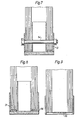
- the end closures 12, 13 can alternately be attached directly to the end parts of the casing 11 as shown in Figs. 7-9. In the embodiment according to Fig. 7 this is done by drilling a hole through the end caps 16, 17 and the casing 11 and inserting a bolt 54 in the hole.
- the two end caps or sockets 16, 17 are welded to the ends of the casing by welding seam 55 between the sleeve portion of the socket and the part of the casing that is not folded.
- the welding seam 55 is applied to the inside of the sleeve as it appears from Fig. 9 and the end cap is finished by welding the bottom plate to the wall portion by a welding seam 56, as can be seen in Fig. 8.
Landscapes
- Engineering & Computer Science (AREA)
- Structural Engineering (AREA)
- Civil Engineering (AREA)
- General Life Sciences & Earth Sciences (AREA)
- Mining & Mineral Resources (AREA)
- Paleontology (AREA)
- General Engineering & Computer Science (AREA)
- Life Sciences & Earth Sciences (AREA)
- Piles And Underground Anchors (AREA)
- Superconductors And Manufacturing Methods Therefor (AREA)
- Glass Compositions (AREA)
- Window Of Vehicle (AREA)
- Bulkheads Adapted To Foundation Construction (AREA)
- Mechanical Pencils And Projecting And Retracting Systems Therefor, And Multi-System Writing Instruments (AREA)
- Road Paving Structures (AREA)
- Consolidation Of Soil By Introduction Of Solidifying Substances Into Soil (AREA)
- Addition Polymer Or Copolymer, Post-Treatments, Or Chemical Modifications (AREA)
- Laying Of Electric Cables Or Lines Outside (AREA)
- Footwear And Its Accessory, Manufacturing Method And Apparatuses (AREA)
- Buildings Adapted To Withstand Abnormal External Influences (AREA)
- Earth Drilling (AREA)
- Filling Or Discharging Of Gas Storage Vessels (AREA)
- Absorbent Articles And Supports Therefor (AREA)
Priority Applications (1)
| Application Number | Priority Date | Filing Date | Title |
|---|---|---|---|
| AT83850337T ATE22950T1 (de) | 1982-12-21 | 1983-12-16 | Spannglied. |
Applications Claiming Priority (2)
| Application Number | Priority Date | Filing Date | Title |
|---|---|---|---|
| SE8207291A SE451268B (sv) | 1982-12-21 | 1982-12-21 | Svellkropp for i mark belegna konstruktioner |
| SE8207291 | 1982-12-21 |
Publications (3)
| Publication Number | Publication Date |
|---|---|
| EP0112316A2 EP0112316A2 (en) | 1984-06-27 |
| EP0112316A3 EP0112316A3 (en) | 1984-07-25 |
| EP0112316B1 true EP0112316B1 (en) | 1986-10-15 |
Family
ID=20349084
Family Applications (1)
| Application Number | Title | Priority Date | Filing Date |
|---|---|---|---|
| EP83850337A Expired EP0112316B1 (en) | 1982-12-21 | 1983-12-16 | Expansion body |
Country Status (11)
| Country | Link |
|---|---|
| US (2) | US4571126A (enExample) |
| EP (1) | EP0112316B1 (enExample) |
| JP (1) | JPS59118919A (enExample) |
| AT (1) | ATE22950T1 (enExample) |
| AU (1) | AU567643B2 (enExample) |
| CA (1) | CA1195518A (enExample) |
| DE (1) | DE3366981D1 (enExample) |
| DK (1) | DK155229C (enExample) |
| ES (1) | ES285062Y (enExample) |
| NO (1) | NO162391B (enExample) |
| SE (1) | SE451268B (enExample) |
Families Citing this family (13)
| Publication number | Priority date | Publication date | Assignee | Title |
|---|---|---|---|---|
| SE470406B (sv) * | 1991-07-01 | 1994-02-14 | Soilex Ab | Förfarande för att sätta dragstag och ett dragsteg |
| SE514084C2 (sv) * | 1999-04-21 | 2000-12-18 | Gurlita Maskin Ab | Anordning och metod för armering och tätning av bergvägg innefattande en expander för förankring |
| AT412739B (de) | 2002-01-22 | 2005-06-27 | Techmo Entw & Vertriebs Gmbh | Verfahren und vorrichtung zum bohren eines loches in boden- oder gesteinsmaterial und zum ausbilden einer verankerung |
| SE0202501L (sv) * | 2002-08-23 | 2004-02-24 | Soilex Ab | Sätt att tillverka en påle och/eller ett dragstag |
| AT509159B1 (de) | 2004-03-23 | 2011-09-15 | Alwag Tunnelausbau Gmbh | Verfahren und vorrichtung zum bohren, insbesondere schlag- oder drehschlagbohren, eines lochs in boden- oder gesteinsmaterial und zum ausbilden einer verankerung in dem loch |
| RU2346112C2 (ru) * | 2004-08-30 | 2009-02-10 | ФУТ ФАУНДЭШН А/Эс | Способы создания свайных фундаментов для сооружений, свайные фундаменты и оболочка для создания уширенной подошвы |
| JP4450862B1 (ja) * | 2009-09-01 | 2010-04-14 | 弘和産業株式会社 | 袋体の折り畳み構造 |
| US8221033B2 (en) * | 2009-09-12 | 2012-07-17 | Geopier Foundation Company, Inc. | Extensible shells and related methods for constructing a support pier |
| US9567723B2 (en) | 2010-09-13 | 2017-02-14 | Geopier Foundation Company, Inc. | Open-end extensible shells and related methods for constructing a support pier |
| WO2016011060A1 (en) * | 2014-07-15 | 2016-01-21 | Uretek Usa, Inc. | Rapid pier |
| US10858796B2 (en) | 2015-07-27 | 2020-12-08 | Geopier Foundation Company, Inc. | Extensible shells and related methods for constructing a ductile support pier |
| US11124938B2 (en) * | 2018-09-04 | 2021-09-21 | Ojjo, Inc. | Expanding foundation components and related systems and methods |
| CN109469050A (zh) * | 2018-12-25 | 2019-03-15 | 高永光 | 灌注桩桩底安装中空(孔)环形钢板胶囊(腔)后注浆技术 |
Family Cites Families (9)
| Publication number | Priority date | Publication date | Assignee | Title |
|---|---|---|---|---|
| FR951479A (fr) * | 1942-11-16 | 1949-10-26 | Procédé et appareil permettant de revêtir de bitume chauffé des pieux en béton coulés sur place | |
| US2497377A (en) * | 1947-10-17 | 1950-02-14 | Swann Philip | Pile |
| US2631435A (en) * | 1950-05-05 | 1953-03-17 | John P Emshwiller | Bearing pile |
| GB880736A (en) * | 1958-11-19 | 1961-10-25 | Electricite De France | Improved method of constructing foundations |
| FR1368123A (fr) * | 1963-01-28 | 1964-07-31 | Ct Ex De Rech S Et D Etudes Du | Procédé d'ancrage et dispositif d'ancrage amovible |
| JPS52426A (en) * | 1975-06-23 | 1977-01-05 | Copyer Co Ltd | Transfer device for electrostatic copying machine |
| SU861471A1 (ru) * | 1976-11-19 | 1981-09-07 | За витель В. Г. Федулов | Способ образовани уширени сваи |
| NO159201C (no) * | 1980-09-08 | 1988-12-07 | Atlas Copco Ab | Fremgangsmaate ved bolting i fjell og kombinert ekspansjonsbolt og installasjonsanordning for samme. |
| SE436781B (sv) * | 1981-11-16 | 1985-01-21 | Atlas Copco Ab | Svellkropp |
-
1982
- 1982-12-21 SE SE8207291A patent/SE451268B/sv not_active IP Right Cessation
-
1983
- 1983-12-12 US US06/560,124 patent/US4571126A/en not_active Expired - Lifetime
- 1983-12-14 CA CA000443249A patent/CA1195518A/en not_active Expired
- 1983-12-16 AT AT83850337T patent/ATE22950T1/de not_active IP Right Cessation
- 1983-12-16 DE DE8383850337T patent/DE3366981D1/de not_active Expired
- 1983-12-16 EP EP83850337A patent/EP0112316B1/en not_active Expired
- 1983-12-16 NO NO834643A patent/NO162391B/no unknown
- 1983-12-20 DK DK585583A patent/DK155229C/da not_active IP Right Cessation
- 1983-12-20 AU AU22702/83A patent/AU567643B2/en not_active Ceased
- 1983-12-21 JP JP58240002A patent/JPS59118919A/ja active Granted
- 1983-12-21 ES ES1983285062U patent/ES285062Y/es not_active Expired
-
1986
- 1986-02-05 US US06/826,279 patent/US4661021A/en not_active Expired - Lifetime
Also Published As
| Publication number | Publication date |
|---|---|
| US4661021A (en) | 1987-04-28 |
| SE8207291D0 (sv) | 1982-12-21 |
| DK155229B (da) | 1989-03-06 |
| AU567643B2 (en) | 1987-11-26 |
| ES285062Y (es) | 1986-05-01 |
| EP0112316A2 (en) | 1984-06-27 |
| DK585583D0 (da) | 1983-12-20 |
| DE3366981D1 (en) | 1986-11-20 |
| CA1195518A (en) | 1985-10-22 |
| NO162391B (no) | 1989-09-11 |
| ATE22950T1 (de) | 1986-11-15 |
| NO834643L (no) | 1984-06-22 |
| DK155229C (da) | 1989-07-10 |
| US4571126A (en) | 1986-02-18 |
| SE8207291L (sv) | 1984-06-22 |
| EP0112316A3 (en) | 1984-07-25 |
| DK585583A (da) | 1984-06-22 |
| ES285062U (es) | 1985-08-01 |
| AU2270283A (en) | 1984-06-28 |
| SE451268B (sv) | 1987-09-21 |
| JPH0424489B2 (enExample) | 1992-04-27 |
| JPS59118919A (ja) | 1984-07-09 |
Similar Documents
| Publication | Publication Date | Title |
|---|---|---|
| EP0112316B1 (en) | Expansion body | |
| US4519729A (en) | Segmented membrane barrier | |
| EP1080296B1 (en) | Deformable liner tube | |
| US4487528A (en) | Earth anchoring expansion body having folded sheet metal casing | |
| US5447393A (en) | Building construction methods and materials | |
| EP1375754B1 (en) | A packing apparatus and method for soil nailing | |
| EP0496519B1 (en) | Apparatus for joining water structure sections or the like | |
| DE69905354T2 (de) | Faltbares rohr | |
| US4830536A (en) | Method and apparatus for tunnel lining | |
| US2682152A (en) | Method of and apparatus for reinforcing and supporting mine roofs and the like | |
| US4648220A (en) | Supporting member | |
| US4188140A (en) | Welded joint | |
| JP2614287B2 (ja) | 円筒構造物構築方法および構築用鋼製セグメント | |
| JPH0650002B2 (ja) | 家屋等の建築物の貫通孔を閉塞する閉塞枠および該貫通孔を閉塞する方法 | |
| DE10245648A1 (de) | Verfahren zur Herstellung von Geobarriern für Absperrungen und Abstützungen im Hoch-und Tiefbau sowie Einrichtung zur Durchführung des Verfahrens | |
| JPS5912809B2 (ja) | 山止め壁の鋼材の引抜工法 | |
| KR860007433A (ko) | 지중매설용 고저조절식 맨홀 | |
| JP2022189654A (ja) | パッカー移動機構及び地山補強工法 | |
| NZ244882A (en) | Trapezoidally corrugated sheetpile exceeding 800mm width and with specified parameters for flange & web extent, thickness, angle etc. | |
| JPH06228949A (ja) | 柱列式地中連続壁 | |
| JPH0133640B2 (enExample) |
Legal Events
| Date | Code | Title | Description |
|---|---|---|---|
| PUAI | Public reference made under article 153(3) epc to a published international application that has entered the european phase |
Free format text: ORIGINAL CODE: 0009012 |
|
| PUAL | Search report despatched |
Free format text: ORIGINAL CODE: 0009013 |
|
| AK | Designated contracting states |
Designated state(s): AT BE CH DE FR GB IT LI LU NL SE |
|
| AK | Designated contracting states |
Designated state(s): AT BE CH DE FR GB IT LI LU NL SE |
|
| 17P | Request for examination filed |
Effective date: 19841212 |
|
| RAP1 | Party data changed (applicant data changed or rights of an application transferred) |
Owner name: ATLAS COPCO AKTIEBOLAG |
|
| 17Q | First examination report despatched |
Effective date: 19860219 |
|
| ITF | It: translation for a ep patent filed | ||
| GRAA | (expected) grant |
Free format text: ORIGINAL CODE: 0009210 |
|
| AK | Designated contracting states |
Kind code of ref document: B1 Designated state(s): AT BE CH DE FR GB IT LI LU NL SE |
|
| PG25 | Lapsed in a contracting state [announced via postgrant information from national office to epo] |
Ref country code: AT Effective date: 19861015 |
|
| REF | Corresponds to: |
Ref document number: 22950 Country of ref document: AT Date of ref document: 19861115 Kind code of ref document: T |
|
| REF | Corresponds to: |
Ref document number: 3366981 Country of ref document: DE Date of ref document: 19861120 |
|
| ET | Fr: translation filed | ||
| PLBE | No opposition filed within time limit |
Free format text: ORIGINAL CODE: 0009261 |
|
| STAA | Information on the status of an ep patent application or granted ep patent |
Free format text: STATUS: NO OPPOSITION FILED WITHIN TIME LIMIT |
|
| 26N | No opposition filed | ||
| ITTA | It: last paid annual fee | ||
| PGFP | Annual fee paid to national office [announced via postgrant information from national office to epo] |
Ref country code: LU Payment date: 19911218 Year of fee payment: 9 |
|
| EPTA | Lu: last paid annual fee | ||
| PG25 | Lapsed in a contracting state [announced via postgrant information from national office to epo] |
Ref country code: LU Free format text: LAPSE BECAUSE OF NON-PAYMENT OF DUE FEES Effective date: 19921216 |
|
| PGFP | Annual fee paid to national office [announced via postgrant information from national office to epo] |
Ref country code: CH Payment date: 19931215 Year of fee payment: 11 |
|
| PGFP | Annual fee paid to national office [announced via postgrant information from national office to epo] |
Ref country code: BE Payment date: 19940131 Year of fee payment: 11 |
|
| PG25 | Lapsed in a contracting state [announced via postgrant information from national office to epo] |
Ref country code: LI Effective date: 19941231 Ref country code: CH Effective date: 19941231 Ref country code: BE Effective date: 19941231 |
|
| EAL | Se: european patent in force in sweden |
Ref document number: 83850337.3 |
|
| BERE | Be: lapsed |
Owner name: ATLAS COPCO A.B. Effective date: 19941231 |
|
| REG | Reference to a national code |
Ref country code: CH Ref legal event code: PL |
|
| PGFP | Annual fee paid to national office [announced via postgrant information from national office to epo] |
Ref country code: FR Payment date: 19951212 Year of fee payment: 13 |
|
| PGFP | Annual fee paid to national office [announced via postgrant information from national office to epo] |
Ref country code: NL Payment date: 19951230 Year of fee payment: 13 |
|
| PG25 | Lapsed in a contracting state [announced via postgrant information from national office to epo] |
Ref country code: NL Effective date: 19970701 |
|
| PG25 | Lapsed in a contracting state [announced via postgrant information from national office to epo] |
Ref country code: FR Effective date: 19970829 |
|
| NLV4 | Nl: lapsed or anulled due to non-payment of the annual fee |
Effective date: 19970701 |
|
| REG | Reference to a national code |
Ref country code: FR Ref legal event code: ST |
|
| PGFP | Annual fee paid to national office [announced via postgrant information from national office to epo] |
Ref country code: DE Payment date: 19981229 Year of fee payment: 16 |
|
| PG25 | Lapsed in a contracting state [announced via postgrant information from national office to epo] |
Ref country code: DE Free format text: LAPSE BECAUSE OF NON-PAYMENT OF DUE FEES Effective date: 20001003 |
|
| REG | Reference to a national code |
Ref country code: GB Ref legal event code: IF02 |
|
| PGFP | Annual fee paid to national office [announced via postgrant information from national office to epo] |
Ref country code: SE Payment date: 20021204 Year of fee payment: 20 |
|
| PGFP | Annual fee paid to national office [announced via postgrant information from national office to epo] |
Ref country code: GB Payment date: 20021211 Year of fee payment: 20 |
|
| PG25 | Lapsed in a contracting state [announced via postgrant information from national office to epo] |
Ref country code: GB Free format text: LAPSE BECAUSE OF EXPIRATION OF PROTECTION Effective date: 20031215 |
|
| REG | Reference to a national code |
Ref country code: GB Ref legal event code: PE20 |
|
| EUG | Se: european patent has lapsed |