EP0112316A2 - Expansion body - Google Patents
Expansion body Download PDFInfo
- Publication number
- EP0112316A2 EP0112316A2 EP83850337A EP83850337A EP0112316A2 EP 0112316 A2 EP0112316 A2 EP 0112316A2 EP 83850337 A EP83850337 A EP 83850337A EP 83850337 A EP83850337 A EP 83850337A EP 0112316 A2 EP0112316 A2 EP 0112316A2
- Authority
- EP
- European Patent Office
- Prior art keywords
- casing
- socket
- expansion body
- body according
- folds
- Prior art date
- Legal status (The legal status is an assumption and is not a legal conclusion. Google has not performed a legal analysis and makes no representation as to the accuracy of the status listed.)
- Granted
Links
Images


Classifications
-
- E—FIXED CONSTRUCTIONS
- E02—HYDRAULIC ENGINEERING; FOUNDATIONS; SOIL SHIFTING
- E02D—FOUNDATIONS; EXCAVATIONS; EMBANKMENTS; UNDERGROUND OR UNDERWATER STRUCTURES
- E02D5/00—Bulkheads, piles, or other structural elements specially adapted to foundation engineering
- E02D5/74—Means for anchoring structural elements or bulkheads
- E02D5/80—Ground anchors
- E02D5/805—Ground anchors with deformable anchoring members
-
- E—FIXED CONSTRUCTIONS
- E02—HYDRAULIC ENGINEERING; FOUNDATIONS; SOIL SHIFTING
- E02D—FOUNDATIONS; EXCAVATIONS; EMBANKMENTS; UNDERGROUND OR UNDERWATER STRUCTURES
- E02D5/00—Bulkheads, piles, or other structural elements specially adapted to foundation engineering
- E02D5/22—Piles
- E02D5/54—Piles with prefabricated supports or anchoring parts; Anchoring piles
Definitions
- This invention relates to an expansion body for constructions located in the earth including a folded elongated casing and a first and a second closure arranged at the upper and lower end respectively of the casing, said casing and closures defining an internal closed space connectable to a source of pressurized fluid for the expansion of the body by pressing out the folds of the casing.
- Expansion bodies of the kind mentioned above have been proposed for in situ piles and especially as an expanded foot of these.
- the casing is first inserted into the ground and then filled with pressurized water or concrete for pressing out the folds thereof thus giving the pile its final shape.
- closures A problem related to expansion bodies of that kind has been the arrangement of the end closures.
- said closures must be designed for sealing the end parts of the casing as well as for enabling the foldings to unfold gradually from the ends without causing cracking tensions in the casing.
- the closures are shaped like cone-formed endings of the casing with successively decreasing depths of the foldings. Closures like that are, however, in practice impossible to manufacture for a reasonable cost. They are also unsuitable for closely folded casings or when there is a need for larger inlets or tubes leading through the casing.
- An object of the present invention is to provide an expansion body with end closures which eliminate the drawbacks mentioned above. Another object is to provide an end closure which is simple and cheep to manufacture and mount on the ends of the casing.
- the expansion body according to Fig 1 includes a folded casing 11 and end closures 12, 13 arranged at the upper and lower end 14, 15 respectively of the casing 11.
- the casing 11 which is preferably made of sheet metal is folded in zig-zag shape in a way that appears from Figs 4 and 5 and will be described more in detail later on. In Fig. 1 the folds are only shown schematically.
- Each closure 12, 13 comprises a socket or end cap 16, 17 with a sleeve portion 18, 19 and a bottom portion 20, 21.
- the sleeves 18, 19 have preferably a square cross section in order to closely fit within a predrilled hole in the ground to provide for a high degree of expansion.
- the bottom portions 20, 21 in the form of square plates of steel are welded to the sleeves 18, 19 respectively for forming a sealed ending.
- Tubular spacing means 22 and 23 respectively are welded to each bottom plate 20, 21 to form part of the sockets 16, 17. They have a rectangular cross section and provide annular spaces 24, 25 between themselves and the sleeves 18, 19.
- the spaces 24, 25 are arranged for receiving the end parts 14 and 15 respectively of the casing 11 and each space 24, 25 comprises two wide parts 26 in which the casing is folded and two narrow parts 27 in which the casing is flat (Fig 2).
- the upper closure 12 includes a fitting 28 welded to the bottom plate 20 of the socket 16.
- the fitting 28 has an internal thread 29 for connection with a conduit in the form of a pipe, not shewn, from an external source of pressurized fluid.
- the fluid for example concrete, water or air is conveyed into the internal space of the casing through a passage 30 in the bottom plate.
- a sealing agent 31 is arranged to fill up possible openings between the folds and between the end part 14, 15 of the casing and the socket 16, 17.
- the sealing agent 31 is preferably some viscous substance as for example asphalt but other substances can also be used for example different plastics.
- connection rods or plates 32 are welded to the sockets 16, 17 for retaining them on the casing ends when the pressurized fluid starts to unfold the casing. It might be sufficient with two rods 32 but it is preferred to have four so that the casing can be protected by them during handling, transportation and insertion in the ground especially when the expansion body is rammed into the ground instead of inserted into a pre-bored hole.
- the rods are adapted to follow the contour of the casing during the expansion of the body, see Fig 5, and will thus bring the sockets 16, 17 closer to each other as the body shortens due to the expansion.
- the sockets 16, 17 need not be directly affixed to the respective ends of the casings.
- the expansion body is arranged to be the expanded end of a pile or anchor.
- the non-illustrated tube screwed to the fitting 28 forms the stem of the pile or anchor.
- Reinforcing bars can be inserted through the stem and into the expansion body before concrete is forced into the tube to expand the expansion body and form an integral concrete anchor or pile that consists of a stem and a foot.
- expansion bodies can be arranged on the same stem at desired axial intervals.
- the inner sleeves 22, 23 can then be dispensed with and the stem forming tube can have the same dimension as the sleeves 22, 23.
- the bottom plates 20 can be welded directly to the tube.
- the stem forming tube should then have several big holes into the expansion body for permitting concrete to pass into the expansion body and for providing sufficient concrete bridges between the concrete in the stem and the concrete in the expansion body.
- expansion bodies on pre-formed concrete piles.
- the concrete for expanding the body or bodies can then be injected through a channel in the concrete pile or through conduits outside the pile.
- the pile or anchor with the expansion body or bodies thereon can be inserted into a pre-drilled hole in the ground or they can be forced into the ground.
- the bottom end should be provided with a shoe that can be formed as an arrow point.
- a preferred way of manufacturing the expansion body is to start with rolling an iron sheet to a zig-zag shaped sheet which is cut into smaller sheets of a suitable size.
- Two such sheets 40, 41, see Fig 3 are laid over each other, face to face, so that the folds 42 of the first sheet 40 fall into the folds 43 of the second sheet 41.
- the sheets 40, 41 form an opening 44, 45 of about the same size as the spacing sleeves 22, 23.
- a die beam in the form of a box girder 46 with the same rectangular cross section as the spacing sleeves 22, 23 is arranged to be located in the opening 44, 45 when the two sheets are inserted in each other, see Fig 4.
- Fig 2 is somewhat misleading.
- the spacing sleeve 22 should have the same size in Fig 2 as in Fig 1.
- the two longitudinal side edges 47, 48 are welded and the double sheet is pressed in a press, not shown, as indicated by the arrows F.
- the pressing is finished when the folds 42, 43 are in close abutment with each other, as in Fig 2.
- the beam 46 is withdrawn from the internal space 49 established by the opening 44, 45 and the sleeves 18, 19 are put onto the ends of the casing 11.
- the spacing sleeves 22, 23, to which bottom plates 20, 21 have been welded are inserted into the internal space 49 and the bottom plates 20, 21 are welded to.the sleeves 18, 19.
- the connecting rods 32 are then attached to the sleeves 18, 19 by welding and the ends of the expansion body are dipped into hot fluent asphalt which fills up and seals possible passages between each end part 14, 15 of the casing 11 and the respective socket 16, 17 as well as between the folds in the socket.
- the asphalt or other sealing agents penetrates also into the folds between the two sheets 40 and 41.
- the end closures 12, 13 so obtained are adapted for keeping the parts of the casing 11 which are located in the sockets 16, 17 in a folded position when the casing outside the sockets is unfolded and expanded. This is achieved since the folds are retained tightly adjacent to each other within the wide parts 26 of the spaces 24, 25 in the sockets. But it is also necessary to provide for some sliding motion in the sockets, otherwise extreme tensions will appear adjacent the sockets which tensions might cause the casing to crack. For that reason the space part 26 is wide enough to allow the folds of the two opposed sheets 40, 41 to move in opposite directions sliding against one another as can be seen in Fig 6.
- the folds 42 and 43 of the first and second sheet 40 and 41 respectively turn about opposite edges 50 and 51 of the sleeves 18, 19 so that the edges bend somewhat outwards.
- the turning and sliding movement is longest for the folds which are located closest to the spacing tube 22 and it decreases successively towards the outer folds.
- the casing 11 may tear up close to the tubes 22 and 23 which results in slits 52, 53 as indicated in Fig 6 but otherwise the casing 11 does not crack.
- the sliding movement is facilitated by the part of the sealing agent 31 which has penetrated inbetween the two sheets 40, 41.
- the pressure needed for expanding the casing 11 varies with the formaton in which it is located.
- the pressure can typically be between a few bars and 50 bars depending on the depth and the formation.
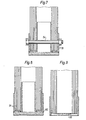
- the end closures 12, 13 can alternatively be attached directly to the end parts of the casing 11 as shown in Figs 7-9. In the embodiment according to Fig 7 this is done by drilling a hole through the end caps 16, 17 and the casing 11 and inserting a bolt 54 in the hole.
- the end caps or sockets 16, 17 are welded to the ends of the casing by welding seam 55 between the sleeve portion of the socket and the part of the casing that is not folded.
- the welding seam 55 is applied to the inside of the sleeve as appears from Fig 9 and the end cap is finished by welding the bottom plate to the wall portion by a welding seam 56, as can be see in Fig 8.
Abstract
Description
- This invention relates to an expansion body for constructions located in the earth including a folded elongated casing and a first and a second closure arranged at the upper and lower end respectively of the casing, said casing and closures defining an internal closed space connectable to a source of pressurized fluid for the expansion of the body by pressing out the folds of the casing.
- Expansion bodies of the kind mentioned above have been proposed for in situ piles and especially as an expanded foot of these. When such piles are used, the casing is first inserted into the ground and then filled with pressurized water or concrete for pressing out the folds thereof thus giving the pile its final shape.
- A problem related to expansion bodies of that kind has been the arrangement of the end closures. The reason for this is that said closures must be designed for sealing the end parts of the casing as well as for enabling the foldings to unfold gradually from the ends without causing cracking tensions in the casing. According to one known proposal for such an expansion body, the closures are shaped like cone-formed endings of the casing with successively decreasing depths of the foldings. Closures like that are, however, in practice impossible to manufacture for a reasonable cost. They are also unsuitable for closely folded casings or when there is a need for larger inlets or tubes leading through the casing.
- An object of the present invention is to provide an expansion body with end closures which eliminate the drawbacks mentioned above. Another object is to provide an end closure which is simple and cheep to manufacture and mount on the ends of the casing.
- These objects and others are achieved by providing an expansion body according to the accompanying claims.
- The invention will now be described more in detail in connecton with the enclosed drawings wherein:
- Fig 1 is a longitudinal cross section of an expansion body according to the invention. The section is taken along the line 1-1 in Fig. 2.
- Fig 2 is a cross section according to the line 2-2 in Fig 1.
- Figs 3 and 4 are a cross section of two sheets and a die beam, showing schematically the manufacture of the expansion body according to Fig 1.
- Fig 5 is a side view of an expanded body according to Fig 1.
- Fig 6 is a cross section according to the line 6-6 in Fig 5.
- Fig 7 is a longitudinal cross section of the lower end part of the casing with an alternative attachment between the closure and the casing.
- Fig 8 is the same section as Fig 7 but showing still another attachment.
- Fig 9 shows the closure according to Fig 8 partly finished.
- The expansion body according to Fig 1 includes a folded
casing 11 andend closures lower end casing 11. Thecasing 11 which is preferably made of sheet metal is folded in zig-zag shape in a way that appears from Figs 4 and 5 and will be described more in detail later on. In Fig. 1 the folds are only shown schematically. Eachclosure end cap sleeve portion bottom portion sleeves bottom portions sleeves bottom plate sockets annular spaces sleeves spaces end parts casing 11 and eachspace wide parts 26 in which the casing is folded and twonarrow parts 27 in which the casing is flat (Fig 2). - The
upper closure 12 includes afitting 28 welded to thebottom plate 20 of thesocket 16. Thefitting 28 has aninternal thread 29 for connection with a conduit in the form of a pipe, not shewn, from an external source of pressurized fluid. The fluid, for example concrete, water or air is conveyed into the internal space of the casing through apassage 30 in the bottom plate. To prevent the fluid from leaking between the folds in the socket, asealing agent 31 is arranged to fill up possible openings between the folds and between theend part socket sealing agent 31 is preferably some viscous substance as for example asphalt but other substances can also be used for example different plastics. - Four connecting rods or
plates 32 are welded to thesockets rods 32 but it is preferred to have four so that the casing can be protected by them during handling, transportation and insertion in the ground especially when the expansion body is rammed into the ground instead of inserted into a pre-bored hole. The rods are adapted to follow the contour of the casing during the expansion of the body, see Fig 5, and will thus bring thesockets sockets - In the embodiment described above, the expansion body is arranged to be the expanded end of a pile or anchor. The non-illustrated tube screwed to the fitting 28 forms the stem of the pile or anchor. Reinforcing bars can be inserted through the stem and into the expansion body before concrete is forced into the tube to expand the expansion body and form an integral concrete anchor or pile that consists of a stem and a foot.
- Several expansion bodies can be arranged on the same stem at desired axial intervals. The
inner sleeves sleeves bottom plates 20 can be welded directly to the tube. The stem forming tube should then have several big holes into the expansion body for permitting concrete to pass into the expansion body and for providing sufficient concrete bridges between the concrete in the stem and the concrete in the expansion body. - It is also possible to arrange the expansion bodies on pre-formed concrete piles. The concrete for expanding the body or bodies can then be injected through a channel in the concrete pile or through conduits outside the pile.
- In all the embodiments described, the pile or anchor with the expansion body or bodies thereon can be inserted into a pre-drilled hole in the ground or they can be forced into the ground. When they are forced into the ground, the bottom end should be provided with a shoe that can be formed as an arrow point.
- A preferred way of manufacturing the expansion body is to start with rolling an iron sheet to a zig-zag shaped sheet which is cut into smaller sheets of a suitable size. Two
such sheets 40, 41, see Fig 3, are laid over each other, face to face, so that thefolds 42 of thefirst sheet 40 fall into thefolds 43 of the second sheet 41. Along their middle portions, thesheets 40, 41 form an opening 44, 45 of about the same size as thespacing sleeves box girder 46 with the same rectangular cross section as thespacing sleeves opening spacing sleeve 22 should have the same size in Fig 2 as in Fig 1. - The two
longitudinal side edges folds beam 46 is withdrawn from theinternal space 49 established by the opening 44, 45 and thesleeves casing 11. Then, thespacing sleeves bottom plates internal space 49 and thebottom plates sleeves rods 32 are then attached to thesleeves end part casing 11 and therespective socket sheets 40 and 41. - The
end closures casing 11 which are located in thesockets wide parts 26 of thespaces space part 26 is wide enough to allow the folds of the two opposedsheets 40, 41 to move in opposite directions sliding against one another as can be seen in Fig 6. Thefolds second sheet 40 and 41 respectively turn aboutopposite edges sleeves spacing tube 22 and it decreases successively towards the outer folds. Thecasing 11 may tear up close to thetubes slits casing 11 does not crack. The sliding movement is facilitated by the part of the sealingagent 31 which has penetrated inbetween the twosheets 40, 41. - The pressure needed for expanding the
casing 11 varies with the formaton in which it is located. The pressure can typically be between a few bars and 50 bars depending on the depth and the formation. In application for which a comparatively low pressure is sufficient, theend closures casing 11 as shown in Figs 7-9. In the embodiment according to Fig 7 this is done by drilling a hole through the end caps 16, 17 and thecasing 11 and inserting abolt 54 in the hole. In another embodiment according to Figs 8 and 9 the end caps orsockets seam 55 between the sleeve portion of the socket and the part of the casing that is not folded. Thewelding seam 55 is applied to the inside of the sleeve as appears from Fig 9 and the end cap is finished by welding the bottom plate to the wall portion by awelding seam 56, as can be see in Fig 8. - It is to be understood that the invention is not limited to the disclosed examples but can be varied in many ways within the scope of the claims. For example the casing can be folded in other ways.
Claims (10)
characterized in n
that at least one of the closures (12, 13) comprises a sealing socket (16, 17) with a sleeve (18, 19) encircling one end part (14, 15) of the casing, said socket (16, 17) being adapted for keeping the folds (42, 43) located within the socket in a folded position when the body is expanded.
characterized in n
that a sealing agent (31) is arranged in said socket (16, 17) between the folds of said casing (11) and between the casing and the socket.
characterized in n
that said socket (16, 17) is attached to said casing (11) by attaching means (32; 50; 51) which substantially prevents relative axial movement between said socket and casing but allows the folds (42, 43) located within the socket to turn in relation to said socket.
characterized in n
that said socket includes a tube-shaped spacing means (22, 23) projecting in parallel with the sleeve (18, 19) into said internal space (49).
characterized in
that said attaching means comprises one or more connecting bars (32) mounted to the socket (16, 17) and extending between said socket and the closure at the opposite end of the casing.
characterized in n
that the connecting elements (32) extend along the outside of the casing.
characterized in
that said closure at the opposite end of the casing comprises a second socket, said connecting elements (32) being connected to said second socket.
characterized i n
that the socket (16 and 17 respectively) is attached to the adjacent end part (14 and 15 respectively) of the casing.
characterized in
that said socket (16, 17) comprises a bottom plate (20, 21) attached to the sleeve (18, 19) and to the spacing means (22, 23) for forming a sealed bottom portion.
characterized i n
that an annular space (26, 27) is provided between the sleeve (18, 19) and the spacing means (22, 23) said space comprising a wide part (26) in which the casing (11) is folded and a narrow part (27) in which the casing is not folded.
Priority Applications (1)
| Application Number | Priority Date | Filing Date | Title |
|---|---|---|---|
| AT83850337T ATE22950T1 (en) | 1982-12-21 | 1983-12-16 | TENSIONING LINK. |
Applications Claiming Priority (2)
| Application Number | Priority Date | Filing Date | Title |
|---|---|---|---|
| SE8207291A SE451268B (en) | 1982-12-21 | 1982-12-21 | SWELL BODY FOR MARK LOCATION CONSTRUCTIONS |
| SE8207291 | 1982-12-21 |
Publications (3)
| Publication Number | Publication Date |
|---|---|
| EP0112316A2 true EP0112316A2 (en) | 1984-06-27 |
| EP0112316A3 EP0112316A3 (en) | 1984-07-25 |
| EP0112316B1 EP0112316B1 (en) | 1986-10-15 |
Family
ID=20349084
Family Applications (1)
| Application Number | Title | Priority Date | Filing Date |
|---|---|---|---|
| EP83850337A Expired EP0112316B1 (en) | 1982-12-21 | 1983-12-16 | Expansion body |
Country Status (11)
| Country | Link |
|---|---|
| US (2) | US4571126A (en) |
| EP (1) | EP0112316B1 (en) |
| JP (1) | JPS59118919A (en) |
| AT (1) | ATE22950T1 (en) |
| AU (1) | AU567643B2 (en) |
| CA (1) | CA1195518A (en) |
| DE (1) | DE3366981D1 (en) |
| DK (1) | DK155229C (en) |
| ES (1) | ES285062Y (en) |
| NO (1) | NO162391B (en) |
| SE (1) | SE451268B (en) |
Cited By (3)
| Publication number | Priority date | Publication date | Assignee | Title |
|---|---|---|---|---|
| WO1993001360A1 (en) * | 1991-07-01 | 1993-01-21 | Soilex Ab | A method of installing a soil anchor and a soil anchor |
| WO2003062599A1 (en) | 2002-01-22 | 2003-07-31 | Techmo Entwicklungs- Und Vertriebs Gmbh | Rock bolts with an expandable element |
| US7320371B2 (en) | 2004-03-23 | 2008-01-22 | “ALWAG” Tunnelausbau Gesellschaft m.b.H. | Method and device for producing pretensioned anchorings |
Families Citing this family (9)
| Publication number | Priority date | Publication date | Assignee | Title |
|---|---|---|---|---|
| SE514084C2 (en) * | 1999-04-21 | 2000-12-18 | Gurlita Maskin Ab | Device and method for reinforcing and sealing rock wall including an expander for anchoring |
| SE0202501L (en) * | 2002-08-23 | 2004-02-24 | Soilex Ab | Ways to make a pole and / or a tie rod |
| JP4450862B1 (en) * | 2009-09-01 | 2010-04-14 | 弘和産業株式会社 | Folding structure of bag |
| US8221033B2 (en) * | 2009-09-12 | 2012-07-17 | Geopier Foundation Company, Inc. | Extensible shells and related methods for constructing a support pier |
| US9567723B2 (en) | 2010-09-13 | 2017-02-14 | Geopier Foundation Company, Inc. | Open-end extensible shells and related methods for constructing a support pier |
| US9988784B2 (en) * | 2014-07-15 | 2018-06-05 | Uretek Usa, Inc. | Rapid pier |
| US10858796B2 (en) * | 2015-07-27 | 2020-12-08 | Geopier Foundation Company, Inc. | Extensible shells and related methods for constructing a ductile support pier |
| US11124938B2 (en) * | 2018-09-04 | 2021-09-21 | Ojjo, Inc. | Expanding foundation components and related systems and methods |
| CN109469050A (en) * | 2018-12-25 | 2019-03-15 | 高永光 | Grout pile bottom is installed by hollow (hole) doughnut-shaped steel plate capsule (chamber) Post Grouting Technique |
Citations (3)
| Publication number | Priority date | Publication date | Assignee | Title |
|---|---|---|---|---|
| US2497377A (en) * | 1947-10-17 | 1950-02-14 | Swann Philip | Pile |
| GB1034033A (en) * | 1963-01-28 | 1966-06-29 | Ct Ex De Rech S Et D Etudes Du | Improvements in or relating to methods and means for anchoring articles to the ground or other media |
| DE2131033A1 (en) * | 1971-06-23 | 1972-12-28 | Klammt Kg Baugesellschaft | Ground anchor |
Family Cites Families (7)
| Publication number | Priority date | Publication date | Assignee | Title |
|---|---|---|---|---|
| FR951479A (en) * | 1942-11-16 | 1949-10-26 | Method and apparatus for coating cast-in-place concrete piles with heated bitumen | |
| US2631435A (en) * | 1950-05-05 | 1953-03-17 | John P Emshwiller | Bearing pile |
| GB880736A (en) * | 1958-11-19 | 1961-10-25 | Electricite De France | Improved method of constructing foundations |
| JPS52426A (en) * | 1975-06-23 | 1977-01-05 | Copyer Co Ltd | Transfer device for electrostatic copying machine |
| SU861471A1 (en) * | 1976-11-19 | 1981-09-07 | За витель В. Г. Федулов | Method of windening pile |
| NO159201C (en) * | 1980-09-08 | 1988-12-07 | Atlas Copco Ab | PROCEDURE FOR BOLTING IN MOUNTAIN AND COMBINED EXPANSION BOLT AND INSTALLATION DEVICE FOR SAME. |
| SE436781B (en) * | 1981-11-16 | 1985-01-21 | Atlas Copco Ab | SVELLKROPP |
-
1982
- 1982-12-21 SE SE8207291A patent/SE451268B/en not_active IP Right Cessation
-
1983
- 1983-12-12 US US06/560,124 patent/US4571126A/en not_active Expired - Lifetime
- 1983-12-14 CA CA000443249A patent/CA1195518A/en not_active Expired
- 1983-12-16 DE DE8383850337T patent/DE3366981D1/en not_active Expired
- 1983-12-16 AT AT83850337T patent/ATE22950T1/en not_active IP Right Cessation
- 1983-12-16 NO NO834643A patent/NO162391B/en unknown
- 1983-12-16 EP EP83850337A patent/EP0112316B1/en not_active Expired
- 1983-12-20 AU AU22702/83A patent/AU567643B2/en not_active Ceased
- 1983-12-20 DK DK585583A patent/DK155229C/en not_active IP Right Cessation
- 1983-12-21 JP JP58240002A patent/JPS59118919A/en active Granted
- 1983-12-21 ES ES1983285062U patent/ES285062Y/en not_active Expired
-
1986
- 1986-02-05 US US06/826,279 patent/US4661021A/en not_active Expired - Lifetime
Patent Citations (3)
| Publication number | Priority date | Publication date | Assignee | Title |
|---|---|---|---|---|
| US2497377A (en) * | 1947-10-17 | 1950-02-14 | Swann Philip | Pile |
| GB1034033A (en) * | 1963-01-28 | 1966-06-29 | Ct Ex De Rech S Et D Etudes Du | Improvements in or relating to methods and means for anchoring articles to the ground or other media |
| DE2131033A1 (en) * | 1971-06-23 | 1972-12-28 | Klammt Kg Baugesellschaft | Ground anchor |
Cited By (5)
| Publication number | Priority date | Publication date | Assignee | Title |
|---|---|---|---|---|
| WO1993001360A1 (en) * | 1991-07-01 | 1993-01-21 | Soilex Ab | A method of installing a soil anchor and a soil anchor |
| US5465535A (en) * | 1991-07-01 | 1995-11-14 | Soilex Ab | Method of installing a soil anchor and a soil anchor |
| WO2003062599A1 (en) | 2002-01-22 | 2003-07-31 | Techmo Entwicklungs- Und Vertriebs Gmbh | Rock bolts with an expandable element |
| US7004686B2 (en) | 2002-01-22 | 2006-02-28 | Techmo Entwicklungs- Und Vertriebs Gmbh | Rock bolts with expandable element |
| US7320371B2 (en) | 2004-03-23 | 2008-01-22 | “ALWAG” Tunnelausbau Gesellschaft m.b.H. | Method and device for producing pretensioned anchorings |
Also Published As
| Publication number | Publication date |
|---|---|
| EP0112316A3 (en) | 1984-07-25 |
| DE3366981D1 (en) | 1986-11-20 |
| AU567643B2 (en) | 1987-11-26 |
| DK585583A (en) | 1984-06-22 |
| EP0112316B1 (en) | 1986-10-15 |
| US4661021A (en) | 1987-04-28 |
| NO834643L (en) | 1984-06-22 |
| US4571126A (en) | 1986-02-18 |
| DK155229B (en) | 1989-03-06 |
| JPS59118919A (en) | 1984-07-09 |
| ATE22950T1 (en) | 1986-11-15 |
| DK155229C (en) | 1989-07-10 |
| SE451268B (en) | 1987-09-21 |
| AU2270283A (en) | 1984-06-28 |
| ES285062U (en) | 1985-08-01 |
| JPH0424489B2 (en) | 1992-04-27 |
| DK585583D0 (en) | 1983-12-20 |
| SE8207291D0 (en) | 1982-12-21 |
| ES285062Y (en) | 1986-05-01 |
| NO162391B (en) | 1989-09-11 |
| CA1195518A (en) | 1985-10-22 |
| SE8207291L (en) | 1984-06-22 |
Similar Documents
| Publication | Publication Date | Title |
|---|---|---|
| EP1375754B1 (en) | A packing apparatus and method for soil nailing | |
| CA2270586C (en) | Composite pile | |
| US4487528A (en) | Earth anchoring expansion body having folded sheet metal casing | |
| EP0112316B1 (en) | Expansion body | |
| US4519729A (en) | Segmented membrane barrier | |
| EP1080296B1 (en) | Deformable liner tube | |
| EP0394179B1 (en) | Combined rigid profile and extension anchor with expansion element | |
| US5447393A (en) | Building construction methods and materials | |
| CA1171310A (en) | Expanding hollow tube rock stabilizer | |
| US4305680A (en) | Roadway joint and seal and method of fabricating same | |
| US2682152A (en) | Method of and apparatus for reinforcing and supporting mine roofs and the like | |
| US4648220A (en) | Supporting member | |
| CH574023A5 (en) | Junction seal for channels or conduits - has ring expansion member anchored to one channel inflated to force ends apart | |
| JPS6227546Y2 (en) | ||
| DE10245648A1 (en) | Process for the production of geobarriers for barriers and supports in civil engineering and device for carrying out the process | |
| JP2565071B2 (en) | Column-type underground continuous wall | |
| EP0916855A1 (en) | Tube connection | |
| JPH0650002B2 (en) | Closure frame for closing through holes of buildings such as houses and method for closing the through holes | |
| JP2022189654A (en) | Packer movement mechanism and ground reinforcement method | |
| JPS5912809B2 (en) | Pulling method of steel material for retaining wall | |
| JPH0731940U (en) | Ground anchor free length sealing device | |
| NZ244882A (en) | Trapezoidally corrugated sheetpile exceeding 800mm width and with specified parameters for flange & web extent, thickness, angle etc. | |
| JPH06185053A (en) | Rock anchor |
Legal Events
| Date | Code | Title | Description |
|---|---|---|---|
| PUAI | Public reference made under article 153(3) epc to a published international application that has entered the european phase |
Free format text: ORIGINAL CODE: 0009012 |
|
| PUAL | Search report despatched |
Free format text: ORIGINAL CODE: 0009013 |
|
| AK | Designated contracting states |
Designated state(s): AT BE CH DE FR GB IT LI LU NL SE |
|
| AK | Designated contracting states |
Designated state(s): AT BE CH DE FR GB IT LI LU NL SE |
|
| 17P | Request for examination filed |
Effective date: 19841212 |
|
| RAP1 | Party data changed (applicant data changed or rights of an application transferred) |
Owner name: ATLAS COPCO AKTIEBOLAG |
|
| 17Q | First examination report despatched |
Effective date: 19860219 |
|
| ITF | It: translation for a ep patent filed |
Owner name: BARZANO' E ZANARDO ROMA S.P.A. |
|
| GRAA | (expected) grant |
Free format text: ORIGINAL CODE: 0009210 |
|
| AK | Designated contracting states |
Kind code of ref document: B1 Designated state(s): AT BE CH DE FR GB IT LI LU NL SE |
|
| PG25 | Lapsed in a contracting state [announced via postgrant information from national office to epo] |
Ref country code: AT Effective date: 19861015 |
|
| REF | Corresponds to: |
Ref document number: 22950 Country of ref document: AT Date of ref document: 19861115 Kind code of ref document: T |
|
| REF | Corresponds to: |
Ref document number: 3366981 Country of ref document: DE Date of ref document: 19861120 |
|
| ET | Fr: translation filed | ||
| PLBE | No opposition filed within time limit |
Free format text: ORIGINAL CODE: 0009261 |
|
| STAA | Information on the status of an ep patent application or granted ep patent |
Free format text: STATUS: NO OPPOSITION FILED WITHIN TIME LIMIT |
|
| 26N | No opposition filed | ||
| ITTA | It: last paid annual fee | ||
| PGFP | Annual fee paid to national office [announced via postgrant information from national office to epo] |
Ref country code: LU Payment date: 19911218 Year of fee payment: 9 |
|
| EPTA | Lu: last paid annual fee | ||
| PG25 | Lapsed in a contracting state [announced via postgrant information from national office to epo] |
Ref country code: LU Free format text: LAPSE BECAUSE OF NON-PAYMENT OF DUE FEES Effective date: 19921216 |
|
| PGFP | Annual fee paid to national office [announced via postgrant information from national office to epo] |
Ref country code: CH Payment date: 19931215 Year of fee payment: 11 |
|
| PGFP | Annual fee paid to national office [announced via postgrant information from national office to epo] |
Ref country code: BE Payment date: 19940131 Year of fee payment: 11 |
|
| PG25 | Lapsed in a contracting state [announced via postgrant information from national office to epo] |
Ref country code: LI Effective date: 19941231 Ref country code: CH Effective date: 19941231 Ref country code: BE Effective date: 19941231 |
|
| EAL | Se: european patent in force in sweden |
Ref document number: 83850337.3 |
|
| BERE | Be: lapsed |
Owner name: ATLAS COPCO A.B. Effective date: 19941231 |
|
| REG | Reference to a national code |
Ref country code: CH Ref legal event code: PL |
|
| PGFP | Annual fee paid to national office [announced via postgrant information from national office to epo] |
Ref country code: FR Payment date: 19951212 Year of fee payment: 13 |
|
| PGFP | Annual fee paid to national office [announced via postgrant information from national office to epo] |
Ref country code: NL Payment date: 19951230 Year of fee payment: 13 |
|
| PG25 | Lapsed in a contracting state [announced via postgrant information from national office to epo] |
Ref country code: NL Effective date: 19970701 |
|
| PG25 | Lapsed in a contracting state [announced via postgrant information from national office to epo] |
Ref country code: FR Effective date: 19970829 |
|
| NLV4 | Nl: lapsed or anulled due to non-payment of the annual fee |
Effective date: 19970701 |
|
| REG | Reference to a national code |
Ref country code: FR Ref legal event code: ST |
|
| PGFP | Annual fee paid to national office [announced via postgrant information from national office to epo] |
Ref country code: DE Payment date: 19981229 Year of fee payment: 16 |
|
| PG25 | Lapsed in a contracting state [announced via postgrant information from national office to epo] |
Ref country code: DE Free format text: LAPSE BECAUSE OF NON-PAYMENT OF DUE FEES Effective date: 20001003 |
|
| REG | Reference to a national code |
Ref country code: GB Ref legal event code: IF02 |
|
| PGFP | Annual fee paid to national office [announced via postgrant information from national office to epo] |
Ref country code: SE Payment date: 20021204 Year of fee payment: 20 |
|
| PGFP | Annual fee paid to national office [announced via postgrant information from national office to epo] |
Ref country code: GB Payment date: 20021211 Year of fee payment: 20 |
|
| PG25 | Lapsed in a contracting state [announced via postgrant information from national office to epo] |
Ref country code: GB Free format text: LAPSE BECAUSE OF EXPIRATION OF PROTECTION Effective date: 20031215 |
|
| REG | Reference to a national code |
Ref country code: GB Ref legal event code: PE20 |
|
| EUG | Se: european patent has lapsed |