EP0111751A2 - Bildeingangsanordnung - Google Patents
Bildeingangsanordnung Download PDFInfo
- Publication number
- EP0111751A2 EP0111751A2 EP83111373A EP83111373A EP0111751A2 EP 0111751 A2 EP0111751 A2 EP 0111751A2 EP 83111373 A EP83111373 A EP 83111373A EP 83111373 A EP83111373 A EP 83111373A EP 0111751 A2 EP0111751 A2 EP 0111751A2
- Authority
- EP
- European Patent Office
- Prior art keywords
- image
- photographing
- input device
- object image
- picture
- Prior art date
- Legal status (The legal status is an assumption and is not a legal conclusion. Google has not performed a legal analysis and makes no representation as to the accuracy of the status listed.)
- Granted
Links
Images
Classifications
-
- G—PHYSICS
- G01—MEASURING; TESTING
- G01N—INVESTIGATING OR ANALYSING MATERIALS BY DETERMINING THEIR CHEMICAL OR PHYSICAL PROPERTIES
- G01N23/00—Investigating or analysing materials by the use of wave or particle radiation, e.g. X-rays or neutrons, not covered by groups G01N3/00 – G01N17/00, G01N21/00 or G01N22/00
- G01N23/02—Investigating or analysing materials by the use of wave or particle radiation, e.g. X-rays or neutrons, not covered by groups G01N3/00 – G01N17/00, G01N21/00 or G01N22/00 by transmitting the radiation through the material
- G01N23/04—Investigating or analysing materials by the use of wave or particle radiation, e.g. X-rays or neutrons, not covered by groups G01N3/00 – G01N17/00, G01N21/00 or G01N22/00 by transmitting the radiation through the material and forming images of the material
-
- H—ELECTRICITY
- H04—ELECTRIC COMMUNICATION TECHNIQUE
- H04N—PICTORIAL COMMUNICATION, e.g. TELEVISION
- H04N23/00—Cameras or camera modules comprising electronic image sensors; Control thereof
- H04N23/30—Cameras or camera modules comprising electronic image sensors; Control thereof for generating image signals from X-rays
Definitions
- the present invention relates to an image input device used in inputting an image into an image processing apparatus.
- angiography is used as one method of diagnosis of the circulatory organs.
- This method consists of inserting a catheter into the heart or blood vessels, injecting a contrast medium into the blood vessels through the catheter, and photographing the flow of the resultant contrast medium by an X-ray photographing apparatus.
- the X-ray image obtained through the irradiation of X-rays is photographed by a TV camera, and the output image signal from the TV camera is converted to a digital signal by an analog-to-digital converter.
- the digital signal is input into a computer, whereby the image processing is carried out.
- portions to be diagnosed might include such portions as, e.g., the heart, which change in shape over time, it is likely that the object to undergo diagnosis will be displaced from the central portion of the picture screen; or, at worst, will be partially or wholly lost from the screen.
- the object of the present invention is to provide an image input device wherein the photographing conditions can be varied in accordance with the variation in position and configuration of the object to be diagnosed and an image thereof can be input while the object image is being kept located in the central portion of the picture screen.
- an image input device comprising a photographing section for photographing a picture including an object to be diagnosed, which object varies in position and configuration over time, an object extracting circuit for extracting an object image by determining the difference in brightness between the two pictures obtained from the photographing section at a prescribed time interval, a position judging circuit for judging whether or not the extracted object is located within a predetermined portion of a picture screen, and a control circuit for controlling the photographing conditions of the photographing section in accordance with the results of judgement made by the position judging circuit.
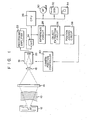
- Fig. 1 is a block diagram of this embodiment.
- An X-ray tube 12 and a fluorescent plate 14 are provided with a patient 10 therebetween.
- the fluorescent X-ray image obtained by the fluorescent plate 14 is photographed by a TV camera 16.
- the fluorescent plate 14 may be replaced by an image intensifier tube.
- the TV camera 16 is comprised of an objective lens 18 and an image pickup tube 20. While the X-ray tube 12 and fluorescent plate 14 are fixedly disposed, the TV camera 16 is made movable in three directions of X, Y and Z.
- the output signal from the image pickup tube 20 is input to a processing amplifier 22.
- the output signal from the processing amplifier 22 is supplied to a CPU 26 and a difference circuit 28 through an analog-to-digital converter 24.
- various image processings such as edge intensifying, etc., are performed with respect to the X-ray image.
- the image thus processed is stored to an external storage device including a magnetic tape 30, magnetic disk 32, floppy disk 34, etc.
- the difference circuit 28 determines the difference in brightness between the two X-ray pictures obtained at a prescribed time interval.
- the difference circuit 28 is comprised of two frame memories and a subtracter.
- the output signal from the difference circuit 28 is supplied to an object extracting circuit 36.
- the signal of the object image extracted by the object extracting circuit 36 is supplied to a position judging circuit 38, in which it is judged whether or not the object image is located within a predetermined portion of a picture screen.
- the output judgement signal from the position judging circuit 38 is supplied - to a camera position controller 40.
- the camera position controller 40 has a mechanism for moving the TV camera 16 in the three directions, i.e., in the X, Y and Z directions.
- a contrast medium is injected to the patient 10. X-rays are irradiated onto that portion of the patient 10 which is to undergo diagnosis.
- the fluorescent X-ray image produced by the fluorescent plate 14 is photographed by the TV camera 16.
- a contrast medium is further injected to the patient 10.
- the output signal from the TV camera 16 is video-processed by the processing amplifier 22, thereby obtaining an image signal of the object in question.
- This image signal is converted to a digital signal by the analog-to-digital converter 24, which digital signal is input into the CPU 26, wherein various image processings are performed on an on-line basis.
- the image thus processed is stored in the external storage device.
- the position of the TV camera 16 is first manually adjusted so that the object image may be located at the central portion of the picture screen. Where the object image is still, or where the variation in configuration and position of the object image, if any, occurs within a small range, the camera position may be fixed. However, where the variation of the object image is wide or large, then the camera position is adjusted as follows so that the object image may be located at all times at the central portion of the picture screen.
- the TV camera 16 is of a motion picture type in which 30 frames are picked up per second. In the difference circuit 28, two picture signals obtained at a prescribed time interval among the output picture signals from the TV camera 16 are sampled.
- These two pictures may be two consecutive pictures, since these pictures are spaced from each other at a time interval corresponding to one frame. Preferably, however, they are more spaced from each other, for example, at a time interval ; corresponding to several frames.
- One of the sampled I picture signals is subtracted from the other, thereby determining a difference therebetween. This difference corresponds to the movement or variation of the object.
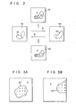
- the state wherein the object is moved or varied is shown in Fig. 2. Assume now that a picture 44 is obtained in a prescribed period of time after a picture 42 is obtained. An object image 45 is enlarged or moves from a state indicated by picture 42 to a state indicated by picture 44 (i.e.., in the direction indicated by arrow A).
- picture 42 is subtracted from picture 44, thereby obtaining a difference picture 46.
- the object image portion in the whole picture screen is made whitish (bright), while the remaining portion thereof is made blackish (dark).
- the difference between the two pictures is obtained as the difference in brightness between the picture cells of one picture and the corresponding picture cells of the other.
- the difference picture consists of three regions, i.e., the ⁇ , ⁇ and 0 regions.
- Concerning the ⁇ region the corresponding object image exists in picture 44, but not in picture 42.
- the ⁇ region the corresponding object image exists in picture 42, but not in picture 44.
- the 0 region the corresponding object image exists or does not exist in picture 44 and in picture 42.
- the object extracting circuit 36 extracts a zone covered by the ⁇ and ⁇ regions.
- the zone covered by these regions is a picture zone wherein any image variation occurs, i.e., an object image zone.
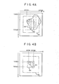
- the position judging circuit 38 judges the position of the extracted zone in the picture screen. Where. the extracted zone 50 covered by the 0 and ⁇ regions is located at the central portion of the picture screen, as shown in Fig. 3A, the object image sufficiently falls within the area of the picture screen. Where the extracted zone 50 is cut off by the side edge of the picture screen as shown in Fig. 3B, the object image is displaced from the central portion of the picture screen, namely is partly lost from the picture screen.
- the maximum value Xmax and minimum value Xmin of the extracted zone 50 in the X direction, and the maximum value Ymax and the minimum value Ymin thereof in the Y direction, are determined respectively, whereby the position of the object image in question is judged as to whether or not it is located within a specified area of the picture screen. Image inputting is effected .on an on-line basis. This specified area, therefore, is defined between an outer boundary 52, with somewhat smaller than the picture screen to provide some allowance for arrangement of the object image and an inner boundary 54 for determining the minimal magnification of the object image.
- the position judging circuit 38 will supply an output judgement signal to the camera position controller 40, to move the TV camera 16 in the X and Y directions.
- the composition of the picture will be so changed that the extracted image zone 50 may fall inside of the outer boundary 52.
- the size of the extracted image zone 50 in the picture screen is very small. Therefore, the magnification of the image in question is required to be increased.
- the increasing of the magnification of the image in question is achieved merely by moving the TV camera 16 in the Z direction to the fluorescent plate 14. Conversely, if the magnification of the object image is so large that all the detected values Xmax, Ymin, Ymax, Xmin are located outside of the outer boundary 52, the TV camera 16 will be moved in the Z direction away from the fluorescent plate 14. Thus, the object image, between the outer boundary 52 and inner boundary 54, is inputted into the CPU 26.
- the composition of the object image can be changed accordingly. Consequently, it is possible to provide an image input device which enables the inputting of an image thereof, while the object image is being kept situated at the central portion of the picture screen, without any loss of the information or signals on the object image. If this image input device is applied to an X-ray image processing apparatus, the image processing can be effected on an on-line basis. This produces the effect of making it possible to shorten the time period required for X-ray photographing, i.e., the time period required for a patient to be exposed to x-rays.
- the present invention is not limited to the above-mentioned embodiment, i.e., to a case wherein an image of the object is input through X-ray photographing.
- This invention can be applied to various modifications which composition is changed according to a difference picture between two pictures photographed.
Landscapes
- Biochemistry (AREA)
- General Physics & Mathematics (AREA)
- Signal Processing (AREA)
- General Health & Medical Sciences (AREA)
- Health & Medical Sciences (AREA)
- Life Sciences & Earth Sciences (AREA)
- Chemical & Material Sciences (AREA)
- Analytical Chemistry (AREA)
- Multimedia (AREA)
- Engineering & Computer Science (AREA)
- Physics & Mathematics (AREA)
- Immunology (AREA)
- Pathology (AREA)
- Closed-Circuit Television Systems (AREA)
- Image Analysis (AREA)
- Apparatus For Radiation Diagnosis (AREA)
- Transforming Light Signals Into Electric Signals (AREA)
- Analysing Materials By The Use Of Radiation (AREA)
- Image Processing (AREA)
Applications Claiming Priority (2)
| Application Number | Priority Date | Filing Date | Title |
|---|---|---|---|
| JP203592/82 | 1982-11-22 | ||
| JP57203592A JPS5994045A (ja) | 1982-11-22 | 1982-11-22 | 画像入力装置 |
Publications (3)
| Publication Number | Publication Date |
|---|---|
| EP0111751A2 true EP0111751A2 (de) | 1984-06-27 |
| EP0111751A3 EP0111751A3 (en) | 1986-10-22 |
| EP0111751B1 EP0111751B1 (de) | 1990-03-14 |
Family
ID=16476617
Family Applications (1)
| Application Number | Title | Priority Date | Filing Date |
|---|---|---|---|
| EP83111373A Expired - Lifetime EP0111751B1 (de) | 1982-11-22 | 1983-11-14 | Bildeingangsanordnung |
Country Status (4)
| Country | Link |
|---|---|
| US (1) | US4626908A (de) |
| EP (1) | EP0111751B1 (de) |
| JP (1) | JPS5994045A (de) |
| DE (1) | DE3381341D1 (de) |
Cited By (3)
| Publication number | Priority date | Publication date | Assignee | Title |
|---|---|---|---|---|
| WO1994010796A1 (de) * | 1992-11-02 | 1994-05-11 | KLINIKUM DER ALBERT-LUDWIGS-UNIVERSITäT FREIBURG | Verfahren und vorrichtung zur bildlagekorrektur von filmbildsequenzen |
| EP0515641A4 (en) * | 1990-11-14 | 1994-05-18 | Cedars Sinai Medical Center | Coronary tracking display |
| WO2014015119A2 (en) | 2012-07-18 | 2014-01-23 | Dow Global Technologies Llc | Fire department and/or antistatic, non-mercury catalyzed polyurethane elastomer |
Families Citing this family (17)
| Publication number | Priority date | Publication date | Assignee | Title |
|---|---|---|---|---|
| US5119190A (en) * | 1963-03-11 | 1992-06-02 | Lemelson Jerome H | Controlling systems and methods for scanning and inspecting images |
| NL8304397A (nl) * | 1983-12-22 | 1985-07-16 | Philips Nv | Roentgenonderzoekapparaat met beeldsubstractie. |
| NZ222404A (en) * | 1987-11-02 | 1991-06-25 | Precision Technology Inc | Vehicle tracking by comparison of transmitted phase at multiple receivers |
| US4937878A (en) * | 1988-08-08 | 1990-06-26 | Hughes Aircraft Company | Signal processing for autonomous acquisition of objects in cluttered background |
| US4959714A (en) * | 1988-08-08 | 1990-09-25 | Hughes Aircraft Company | Segmentation method for terminal aimpoint determination on moving objects and apparatus therefor |
| JP2770192B2 (ja) * | 1989-07-21 | 1998-06-25 | 株式会社島津製作所 | X線ディジタル・サブトラクション装置 |
| JPH0462798A (ja) * | 1990-06-29 | 1992-02-27 | Toshiba Corp | X線診断装置 |
| FR2664153B1 (fr) * | 1990-07-06 | 1992-09-11 | Gen Electric Cgr | Systeme de radiodiagnostic pour examen angiographique avec dispositif automatique de suivi d'embole. |
| JPH04345396A (ja) * | 1991-05-23 | 1992-12-01 | Takayama:Kk | 移動物体追跡方法 |
| JP3038051B2 (ja) * | 1991-06-28 | 2000-05-08 | 日本放送協会 | 動画像領域抽出装置 |
| KR940007163B1 (ko) * | 1991-07-09 | 1994-08-06 | 삼성전자 주식회사 | 캠코더의 피사체 자동추적장치 |
| US5930329A (en) * | 1997-09-22 | 1999-07-27 | Siemens Corporate Research, Inc. | Apparatus and method for detection and localization of a biopsy needle or similar surgical tool in a radiographic image |
| US6055449A (en) * | 1997-09-22 | 2000-04-25 | Siemens Corporate Research, Inc. | Method for localization of a biopsy needle or similar surgical tool in a radiographic image |
| CA2421111A1 (en) * | 2000-08-31 | 2002-03-07 | Rytec Corporation | Sensor and imaging system |
| US7321699B2 (en) | 2002-09-06 | 2008-01-22 | Rytec Corporation | Signal intensity range transformation apparatus and method |
| US20060065844A1 (en) * | 2004-09-30 | 2006-03-30 | Zelakiewicz Scott S | Systems and methods for dynamic optimization of image |
| JP4901448B2 (ja) * | 2006-12-18 | 2012-03-21 | ジーイー・メディカル・システムズ・グローバル・テクノロジー・カンパニー・エルエルシー | X線ct装置 |
Family Cites Families (17)
| Publication number | Priority date | Publication date | Assignee | Title |
|---|---|---|---|---|
| GB1127361A (en) * | 1965-01-30 | 1968-09-18 | Emi Ltd | Improvements relating to pattern recognition devices |
| US3419674A (en) * | 1965-10-14 | 1968-12-31 | Automatic Elect Lab | Image positioning and coupling circuits for television camera and display apparatus |
| US3444380A (en) * | 1966-10-26 | 1969-05-13 | Nasa | Electronic background suppression method and apparatus for a field scanning sensor |
| DE2041530C3 (de) * | 1970-08-21 | 1975-04-03 | Messerschmitt-Boelkow-Blohm Gmbh, 8000 Muenchen | Verfahren zum Fernlenken eines sich selbsttätig bewegenden Körpers und Einrichtung zur Durchführung des Verfahrens |
| DE2354769C3 (de) * | 1973-11-02 | 1982-03-18 | Fa. Carl Zeiss, 7920 Heidenheim | Anordnung zur quantitativen Auswertung der Objekte eines nach einem Rasterverfahren aufgenommenen Bildes |
| GB1590950A (en) * | 1976-12-11 | 1981-06-10 | Emi Ltd | System for comparing representations of a scene |
| JPS5942836B2 (ja) * | 1978-07-24 | 1984-10-17 | シチズン時計株式会社 | アラ−ム時計の構造 |
| JPS55102065A (en) * | 1978-10-31 | 1980-08-04 | Toshiba Corp | Picture processor |
| JPS5573180A (en) * | 1978-11-28 | 1980-06-02 | Nippon Abionikusu Kk | Picture tracking system |
| US4296470A (en) * | 1979-06-21 | 1981-10-20 | International Business Machines Corp. | Link register storage and restore system for use in an instruction pre-fetch micro-processor interrupt system |
| JPS5611560A (en) * | 1979-07-11 | 1981-02-04 | Fuji Electric Co Ltd | Designation system of specific area |
| US4364089A (en) * | 1979-10-31 | 1982-12-14 | Westinghouse Electric Corp. | Binary correlation video tracker |
| DE3043703C2 (de) * | 1980-11-19 | 1983-01-20 | Siemens AG, 1000 Berlin und 8000 München | Röntgendiagnostikeinrichtung zur Erstellung von Subtraktionsbildern |
| US4409615A (en) * | 1980-12-29 | 1983-10-11 | Thomson-Csf Broadcast, Inc. | Video imaging with automatically controlled radiation source |
| US4432014A (en) * | 1981-05-08 | 1984-02-14 | General Electric Company | Video-photo frame size coordinator |
| JPS58147287A (ja) * | 1982-02-26 | 1983-09-02 | Toshiba Corp | 撮像装置 |
| JPS58221932A (ja) * | 1982-06-17 | 1983-12-23 | 株式会社東芝 | 画像入力装置 |
-
1982
- 1982-11-22 JP JP57203592A patent/JPS5994045A/ja active Granted
-
1983
- 1983-11-14 DE DE8383111373T patent/DE3381341D1/de not_active Expired - Lifetime
- 1983-11-14 EP EP83111373A patent/EP0111751B1/de not_active Expired - Lifetime
- 1983-11-22 US US06/554,236 patent/US4626908A/en not_active Expired - Fee Related
Cited By (4)
| Publication number | Priority date | Publication date | Assignee | Title |
|---|---|---|---|---|
| EP0515641A4 (en) * | 1990-11-14 | 1994-05-18 | Cedars Sinai Medical Center | Coronary tracking display |
| US5586201A (en) * | 1990-11-14 | 1996-12-17 | Cedars-Sinai Medical Center | Coronary tracking display |
| WO1994010796A1 (de) * | 1992-11-02 | 1994-05-11 | KLINIKUM DER ALBERT-LUDWIGS-UNIVERSITäT FREIBURG | Verfahren und vorrichtung zur bildlagekorrektur von filmbildsequenzen |
| WO2014015119A2 (en) | 2012-07-18 | 2014-01-23 | Dow Global Technologies Llc | Fire department and/or antistatic, non-mercury catalyzed polyurethane elastomer |
Also Published As
| Publication number | Publication date |
|---|---|
| DE3381341D1 (de) | 1990-04-19 |
| JPS5994045A (ja) | 1984-05-30 |
| EP0111751A3 (en) | 1986-10-22 |
| EP0111751B1 (de) | 1990-03-14 |
| US4626908A (en) | 1986-12-02 |
| JPH0362073B2 (de) | 1991-09-24 |
Similar Documents
| Publication | Publication Date | Title |
|---|---|---|
| US4626908A (en) | Tracking input device | |
| US6501829B2 (en) | Grid holding frame, which provides grid information to X-ray image processing apparatus | |
| EP0146991B1 (de) | Röntgenanlage mit Bildsubtraktion | |
| KR900006419B1 (ko) | X선 촬영장치 | |
| US5978443A (en) | Automated removal of background regions from radiographic images | |
| EP0909527B1 (de) | Röntgenuntersuchungsapparat mit einer anordnung zur belichtungssteuerung | |
| JPH06154198A (ja) | X線診断装置 | |
| DE10195715T5 (de) | Digitales Erfassungsverfahren für Dualenergieabbildung | |
| EP0146992A1 (de) | Röntgen-Untersuchungsgerät mit Selektivfilter | |
| DE69815252T2 (de) | Belichtungssteuerung auf basis von einem bedeutenden teil eines röntgenstrahlbildes | |
| JPH06285061A (ja) | X線診断方法及びその装置 | |
| EP1525849B1 (de) | Fluoroskopiegerät und -Verfahren | |
| CN1025715C (zh) | X射线摄影装置 | |
| EP0374328A1 (de) | Röntgenaufnahmeeinrichtung | |
| JP2907465B2 (ja) | 画像入出力装置 | |
| RU177536U1 (ru) | Цифровая рентгенофлюорографическая камера | |
| EP0102592B1 (de) | Vorrichtung zur Erzeugung von Röntgenbildern | |
| JPH04279153A (ja) | X線条件の自動制御機構 | |
| US4829182A (en) | X-ray image-processing apparatus | |
| JP2722730B2 (ja) | X線透視断層撮影装置 | |
| JPH11290306A (ja) | X線装置 | |
| JP2000333936A (ja) | X線撮影装置 | |
| du Boulay et al. | Telecine Technique Applied to Neuroradiology | |
| EP0101746A1 (de) | System und Verfahren zur dynamischen Hintergrundsubtraktion | |
| JPH03205794A (ja) | X線撮影装置 |
Legal Events
| Date | Code | Title | Description |
|---|---|---|---|
| PUAI | Public reference made under article 153(3) epc to a published international application that has entered the european phase |
Free format text: ORIGINAL CODE: 0009012 |
|
| 17P | Request for examination filed |
Effective date: 19831209 |
|
| AK | Designated contracting states |
Designated state(s): DE FR GB NL |
|
| RAP1 | Party data changed (applicant data changed or rights of an application transferred) |
Owner name: KABUSHIKI KAISHA TOSHIBA |
|
| PUAL | Search report despatched |
Free format text: ORIGINAL CODE: 0009013 |
|
| AK | Designated contracting states |
Kind code of ref document: A3 Designated state(s): DE FR GB NL |
|
| 17Q | First examination report despatched |
Effective date: 19880810 |
|
| GRAA | (expected) grant |
Free format text: ORIGINAL CODE: 0009210 |
|
| AK | Designated contracting states |
Kind code of ref document: B1 Designated state(s): DE FR GB NL |
|
| REF | Corresponds to: |
Ref document number: 3381341 Country of ref document: DE Date of ref document: 19900419 |
|
| ET | Fr: translation filed | ||
| PLBE | No opposition filed within time limit |
Free format text: ORIGINAL CODE: 0009261 |
|
| STAA | Information on the status of an ep patent application or granted ep patent |
Free format text: STATUS: NO OPPOSITION FILED WITHIN TIME LIMIT |
|
| 26N | No opposition filed | ||
| PGFP | Annual fee paid to national office [announced via postgrant information from national office to epo] |
Ref country code: GB Payment date: 19941104 Year of fee payment: 12 |
|
| PG25 | Lapsed in a contracting state [announced via postgrant information from national office to epo] |
Ref country code: GB Effective date: 19951114 |
|
| GBPC | Gb: european patent ceased through non-payment of renewal fee |
Effective date: 19951114 |
|
| PGFP | Annual fee paid to national office [announced via postgrant information from national office to epo] |
Ref country code: FR Payment date: 19961111 Year of fee payment: 14 |
|
| PGFP | Annual fee paid to national office [announced via postgrant information from national office to epo] |
Ref country code: DE Payment date: 19961122 Year of fee payment: 14 |
|
| PGFP | Annual fee paid to national office [announced via postgrant information from national office to epo] |
Ref country code: NL Payment date: 19961128 Year of fee payment: 14 |
|
| PG25 | Lapsed in a contracting state [announced via postgrant information from national office to epo] |
Ref country code: FR Free format text: THE PATENT HAS BEEN ANNULLED BY A DECISION OF A NATIONAL AUTHORITY Effective date: 19971130 |
|
| PG25 | Lapsed in a contracting state [announced via postgrant information from national office to epo] |
Ref country code: NL Free format text: LAPSE BECAUSE OF NON-PAYMENT OF DUE FEES Effective date: 19980601 |
|
| PG25 | Lapsed in a contracting state [announced via postgrant information from national office to epo] |
Ref country code: DE Free format text: LAPSE BECAUSE OF NON-PAYMENT OF DUE FEES Effective date: 19980801 |
|
| NLV4 | Nl: lapsed or anulled due to non-payment of the annual fee |
Effective date: 19980601 |
|
| REG | Reference to a national code |
Ref country code: FR Ref legal event code: ST |