EP0111693A2 - Système de codage pour la saisie d'informations de porteurs mobiles de pièces - Google Patents
Système de codage pour la saisie d'informations de porteurs mobiles de pièces Download PDFInfo
- Publication number
- EP0111693A2 EP0111693A2 EP83110734A EP83110734A EP0111693A2 EP 0111693 A2 EP0111693 A2 EP 0111693A2 EP 83110734 A EP83110734 A EP 83110734A EP 83110734 A EP83110734 A EP 83110734A EP 0111693 A2 EP0111693 A2 EP 0111693A2
- Authority
- EP
- European Patent Office
- Prior art keywords
- information
- coding system
- circuit
- resonant circuit
- information carrier
- Prior art date
- Legal status (The legal status is an assumption and is not a legal conclusion. Google has not performed a legal analysis and makes no representation as to the accuracy of the status listed.)
- Withdrawn
Links
Images
Classifications
-
- G—PHYSICS
- G06—COMPUTING; CALCULATING OR COUNTING
- G06K—GRAPHICAL DATA READING; PRESENTATION OF DATA; RECORD CARRIERS; HANDLING RECORD CARRIERS
- G06K7/00—Methods or arrangements for sensing record carriers, e.g. for reading patterns
- G06K7/08—Methods or arrangements for sensing record carriers, e.g. for reading patterns by means detecting the change of an electrostatic or magnetic field, e.g. by detecting change of capacitance between electrodes
- G06K7/082—Methods or arrangements for sensing record carriers, e.g. for reading patterns by means detecting the change of an electrostatic or magnetic field, e.g. by detecting change of capacitance between electrodes using inductive or magnetic sensors
- G06K7/083—Methods or arrangements for sensing record carriers, e.g. for reading patterns by means detecting the change of an electrostatic or magnetic field, e.g. by detecting change of capacitance between electrodes using inductive or magnetic sensors inductive
- G06K7/086—Methods or arrangements for sensing record carriers, e.g. for reading patterns by means detecting the change of an electrostatic or magnetic field, e.g. by detecting change of capacitance between electrodes using inductive or magnetic sensors inductive sensing passive circuit, e.g. resonant circuit transponders
-
- B—PERFORMING OPERATIONS; TRANSPORTING
- B07—SEPARATING SOLIDS FROM SOLIDS; SORTING
- B07C—POSTAL SORTING; SORTING INDIVIDUAL ARTICLES, OR BULK MATERIAL FIT TO BE SORTED PIECE-MEAL, e.g. BY PICKING
- B07C3/00—Sorting according to destination
- B07C3/10—Apparatus characterised by the means used for detection ofthe destination
- B07C3/12—Apparatus characterised by the means used for detection ofthe destination using electric or electronic detecting means
Definitions
- the mechanical coding systems (DE-OS 30 12 358) have the disadvantage that they are subject to wear and that they are only one allow a very limited number of different information, so that an individual identification of more than 10 workpiece carriers on a conveyor belt or the like is hardly possible.
- a relatively large space for the mechanical coding is required in order to avoid errors when reading the stored information.
- Optically readable coding systems are known in particular for the distribution or detection of packaged goods.
- a large number of thick or thin lines are applied to the packaging in a specific field of the packaging, which lines can then be read by optical sensors.
- Such systems have the disadvantage that they are very sensitive to dirt and consequently can only be used for special / clean manufacturing, sorting and packaging processes.
- Known magnetic coding systems in which the information is applied to the information carrier, for example to a magnetizable sintered material or a metal surface, using strong magnetic fields have the disadvantage that they have a low information density due to the magnetic stray fields in the case of contactless scanning. With a large amount of information, the space required for this is often not available. There is also the risk that iron filings will stick to the magnetized points on the information carrier and prevent the correct reading of the stored information.
- the aim of the present solution is to store a large amount of information in a fail-safe and permanent manner with the smallest possible information carrier on mobile parts, workpieces or workpiece carriers in such a way that it is used in all areas of production, storage, packaging and in shipping systems can be read quickly and reliably using stationary sensors.
- the solution according to the invention with the characterizing features of the main claim has the advantage that the attachment of an information carrier coded by the setting of the resonant circuit requires little space, and that the resonant frequency of the resonant circuit can be sensed by a stationary sensor without an energy source in the information carrier by the resonant circuit of the information carrier acts as a suction circuit and the resonance frequency is detected within a frequency band emitted by the sensor by an impedance change on the sensor.
- Another advantage is that a large number of differently coded information carriers can be used due to a large number of differently set resonant circuits, so that a large number of workpiece carriers, workpieces or other parts on a production line can also be individually identified. This makes it possible with the coding system to provide a central buffer in the production lines instead of individual buffers between different stations, from which the individual workpiece carriers, workpieces or parts are then fed to the correct machines for further processing.
- the resonant circuit of each information carrier from the transmission is to be regarded as particularly advantageous coil, a first capacitor and a further coil in series with the capacitor. This makes it possible to reduce the influence of the distance between the transmitter coil of the information carrier and the sensor on the resonant frequency of the resonant circuit to such an extent that the resonant frequencies can be determined quickly and reliably even with relatively large fluctuations in the air gap between the reading stations and the transmitter coil on the mobile parts can.
- a particularly large amount of coded information from the information memories can be achieved by connecting a plurality of series circuits comprising coils and capacitors to one another and to the transmitter coil in the resonant circuit. In this way, the information memory can be coded to a plurality of resonance frequencies within a certain frequency band and the number of different pieces of information and the number of individually recognizable mobile parts can be increased almost as desired with little effort on the information carrier.
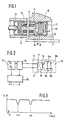
- FIG. 1 shows the outbreak of a workpiece carrier with the information carrier according to the invention in the area of a scanning sensor
- FIG. 2 shows the electrical circuit of the information memory and the scanning sensor with an evaluation circuit
- FIG. 3 shows the impedance of the information carrier measured by the scanning sensor with two resonance points measured over a specific frequency range.
- FIG. 1 the outbreak of such a workpiece carrier of a plurality of workpiece carriers in a production line is shown and designated by 10.
- the workpiece carriers 10 lie on a conveyor belt 11 and serve to hold workpieces that are processed at different stations on the production line.
- the conveyor belt 11 leads the workpiece carriers 10 past various scanning sensors 12, one of which is shown in FIG. 1.
- Each workpiece carrier 10 has an information carrier 13 in which information required for its identification is stored. This information is read out at the various scanning sensors 12 in order to then feed the workpiece picked up in the workpiece carrier 10 to the next work step.
- the information carrier 13 consists essentially of an electrical resonant circuit which contains a transmitter coil 14 with a magnetic circuit which is open at the front and via which the resonant frequency of the resonant circuit can be sensed by the stationary sensors 12.
- the information for identifying the workpiece carrier 10 is thus encoded by tuning the resonant circuit to at least one specific resonance frequency.
- the oscillating circuit is sensed by the scanning sensor 12 via a magnetic field with a sequence of different frequencies.
- the scanning sensor 12 is also provided with a transmitter coil 15 which also contains a magnetic circuit which is open at the front.
- the transmission coil 14 of the mobile workpiece carrier 10 is opposite the transmission coil 15 of the stationary scanning sensor 12.
- the transmitters Coils 14 and 15 are each arranged in a soft magnetic core open at the front, preferably a shell core 16, 17. Behind the shell core 16 of the information carrier 13 there is a printed circuit board 18 which is equipped on one side with capacitors 19 and on the other side with coils 20 and which form lines 21 connected to the transmitter coil 14 to form the electrical resonant circuit.
- the information carrier 13 is embedded in a protective cover 22 which is open at the front and is interchangeably inserted in a bore 23 in the workpiece carrier 10.
- FIG. 2 shows the electrical circuit of the information carrier 13 and the scanning sensor 12 with the evaluation circuit 26 connected to it. From this circuit it can be seen that the resonant circuits in the information carrier 13 consist of two series circuits each of a coil 20a, 20b with a capacitor 19a, 19b, which are connected in parallel to one another and to the transmitter coil 14.
- the leakage inductance of the transmitter coil 14 together with the coils 20a and 20b forms the entire inductance of the resonant circuits in the information carrier 13, but the change in the leakage inductance of the transmitter coil 14 is considerably smaller than the inductance of the coils 20a lying in series with the capacitors 19a, 19b or 20b.
- the leakage inductance of the transmission coil 14 is about 4 mH
- that of the coil 20a is 20 mH
- that of the coil 20b is 4 mH
- the change in the leakage inductance results from different, changing distances between the transmission coils 14 and 15. It is about 1.5 mH.
- the scanning sensor 12 is connected via an impedance measuring stage 24 to a wobble generator 25 which, within a certain frequency range from 10 kHz to 200 kHz, gives a repeated sequence of different frequencies to the transmitter coil 15 of the scanning sensor 12.
- a wobble generator 25 which, within a certain frequency range from 10 kHz to 200 kHz, gives a repeated sequence of different frequencies to the transmitter coil 15 of the scanning sensor 12.
- lower impedance values are measured in the region of the resonance frequencies fo1 and fo2.
- These frequencies of the wobble generator 25 are recorded in an evaluation circuit 26 and, for example, passed on to a central control circuit as a binary number for identification of the workpiece carrier 10.
- the invention is not limited to the exemplary embodiment shown, since the number of resonance elements in the resonant circuit of the information carrier 13 can be limited to one resonance element or can be extended to further additional resonance elements. Likewise, a larger frequency band and thus a larger number of different resonance frequencies can be selected with a sufficient distance from one another in order, if necessary, to obtain further possible combinations.
- resonant circuits however, coding of workpiece carriers, workpieces or other parts can be accommodated in a confined space with a high density of information. The coding can also be carried out separately from the attachment of the transmitter coil by attaching the capacitors.
- the set resonance frequencies on the outside or to provide them with an identification number which corresponds to the binary number read by the scanning sensor 12 and determined in the evaluation circuit 26.
- Such an information carrier is also inexpensive to manufacture, it is simple and robust and largely protected from dirt, moisture and foreign bodies by the protective cover 22. If necessary, it can also be cast in the protective cover 22.
- the protective cover 22 can be pressed in its cylindrical shape into the bore 23, cemented or glued or clamped. In the event of a defect, the information carrier 13 can be replaced quickly and easily.
Landscapes
- Engineering & Computer Science (AREA)
- Artificial Intelligence (AREA)
- Computer Vision & Pattern Recognition (AREA)
- Physics & Mathematics (AREA)
- General Physics & Mathematics (AREA)
- Theoretical Computer Science (AREA)
- General Factory Administration (AREA)
- Geophysics And Detection Of Objects (AREA)
Applications Claiming Priority (2)
| Application Number | Priority Date | Filing Date | Title |
|---|---|---|---|
| DE3242764 | 1982-11-19 | ||
| DE19823242764 DE3242764A1 (de) | 1982-11-19 | 1982-11-19 | Kodiersystem zur erfassung von informationen an mobilen werkstuecktraegern und dgl. |
Publications (2)
| Publication Number | Publication Date |
|---|---|
| EP0111693A2 true EP0111693A2 (fr) | 1984-06-27 |
| EP0111693A3 EP0111693A3 (fr) | 1987-03-25 |
Family
ID=6178480
Family Applications (1)
| Application Number | Title | Priority Date | Filing Date |
|---|---|---|---|
| EP83110734A Withdrawn EP0111693A3 (fr) | 1982-11-19 | 1983-10-27 | Système de codage pour la saisie d'informations de porteurs mobiles de pièces |
Country Status (2)
| Country | Link |
|---|---|
| EP (1) | EP0111693A3 (fr) |
| DE (1) | DE3242764A1 (fr) |
Cited By (10)
| Publication number | Priority date | Publication date | Assignee | Title |
|---|---|---|---|---|
| DE3541676A1 (de) * | 1985-11-26 | 1987-05-27 | Euchner & Co | Identifikationssystem |
| EP0285188A1 (fr) * | 1987-02-16 | 1988-10-05 | N.V. Nederlandsche Apparatenfabriek NEDAP | Procédé pour placer un répondeur électronique dans ou près d'un objet électriquement conducteur et objet électriquement conducteur comportant un tel répondeur |
| US4809426A (en) * | 1985-11-20 | 1989-03-07 | Tokyo Keiki Company, Ltd. | Information processing apparatus of tool holder |
| US4856177A (en) * | 1987-02-10 | 1989-08-15 | Tokyo Keiki Company Ltd. | Automatic tool changer with electromagnetically readable tool holder having an electromagnetically coupling stopper for numerical control |
| EP0389406A2 (fr) * | 1989-03-24 | 1990-09-26 | The Goodyear Tire & Rubber Company | Transmetteur équipé d'un circuit intégré dans un pneumatique pour son identification |
| WO1992003876A1 (fr) * | 1990-08-15 | 1992-03-05 | Vaseal Electronics Limited | Combinaison d'un detecteur de proximite et d'une cible, detecteur de proximite et cible pour une telle combinaison |
| US5357076A (en) * | 1991-04-12 | 1994-10-18 | The Lincoln Electric Company | Plasma torch with identification circuit |
| DE19910935A1 (de) * | 1999-03-12 | 2000-09-21 | Guenter Lang | Etikettenträger, insbesondere zur Kennzeichnung von Werkzeugaufnahmen |
| DE10347591A1 (de) * | 2003-10-14 | 2005-06-02 | Klie, Jürgen, Dr.-Ing. | Mess- und Prüfmittelidentifikationssystem |
| CN110404815A (zh) * | 2019-07-12 | 2019-11-05 | 浙江楠源机械制造有限公司 | 利用立式车床的汽车配件加工方法 |
Families Citing this family (5)
| Publication number | Priority date | Publication date | Assignee | Title |
|---|---|---|---|---|
| DE3607771C3 (de) * | 1986-03-08 | 1996-09-26 | Rolf Hermle | Werkzeughalter mit Datenträger |
| DE3734290A1 (de) * | 1987-10-09 | 1989-04-27 | Rexroth Bernd Gmbh & Co | Lesegeraet fuer ausweiskarten |
| DE3813492C2 (de) * | 1988-04-22 | 1993-12-23 | Euchner & Co | Programmierbare Einrichtung zur codierten Speicherung mindestens eines Zieles für Transportsysteme mit Zielsteuerung |
| DE19631425A1 (de) * | 1996-08-06 | 1998-02-12 | Wolf & Beck Gmbh Dr | Verfahren zur Identifikation von an Meß- oder Werkzeugmaschinen austauschbar angeordneten Zubehörteilen sowie Identifikator zur Verfahrensdurchführung |
| DE202007002838U1 (de) * | 2007-02-27 | 2008-07-03 | Robert Bosch Gmbh | Werkstückidentifikationssystem |
Citations (2)
| Publication number | Priority date | Publication date | Assignee | Title |
|---|---|---|---|---|
| GB1199256A (en) * | 1966-10-06 | 1970-07-22 | Donovan Electrical Company Ltd | Safety Device Primarily for Machine Guards |
| US3752960A (en) * | 1971-12-27 | 1973-08-14 | C Walton | Electronic identification & recognition system |
-
1982
- 1982-11-19 DE DE19823242764 patent/DE3242764A1/de not_active Withdrawn
-
1983
- 1983-10-27 EP EP83110734A patent/EP0111693A3/fr not_active Withdrawn
Patent Citations (2)
| Publication number | Priority date | Publication date | Assignee | Title |
|---|---|---|---|---|
| GB1199256A (en) * | 1966-10-06 | 1970-07-22 | Donovan Electrical Company Ltd | Safety Device Primarily for Machine Guards |
| US3752960A (en) * | 1971-12-27 | 1973-08-14 | C Walton | Electronic identification & recognition system |
Cited By (16)
| Publication number | Priority date | Publication date | Assignee | Title |
|---|---|---|---|---|
| US4809426A (en) * | 1985-11-20 | 1989-03-07 | Tokyo Keiki Company, Ltd. | Information processing apparatus of tool holder |
| DE3541676A1 (de) * | 1985-11-26 | 1987-05-27 | Euchner & Co | Identifikationssystem |
| EP0224226A2 (fr) * | 1985-11-26 | 1987-06-03 | Euchner & Co. | Système d'identification |
| US4720907A (en) * | 1985-11-26 | 1988-01-26 | Euchner & Co. | Identification system |
| EP0224226A3 (fr) * | 1985-11-26 | 1988-02-03 | Euchner & Co. | Système d'identification |
| US4856177A (en) * | 1987-02-10 | 1989-08-15 | Tokyo Keiki Company Ltd. | Automatic tool changer with electromagnetically readable tool holder having an electromagnetically coupling stopper for numerical control |
| EP0285188A1 (fr) * | 1987-02-16 | 1988-10-05 | N.V. Nederlandsche Apparatenfabriek NEDAP | Procédé pour placer un répondeur électronique dans ou près d'un objet électriquement conducteur et objet électriquement conducteur comportant un tel répondeur |
| EP0389406A3 (en) * | 1989-03-24 | 1990-11-28 | The Goodyear Tire & Rubber Company | Integrated circuit transponder in a pneumatic tire for tire identification |
| EP0389406A2 (fr) * | 1989-03-24 | 1990-09-26 | The Goodyear Tire & Rubber Company | Transmetteur équipé d'un circuit intégré dans un pneumatique pour son identification |
| WO1992003876A1 (fr) * | 1990-08-15 | 1992-03-05 | Vaseal Electronics Limited | Combinaison d'un detecteur de proximite et d'une cible, detecteur de proximite et cible pour une telle combinaison |
| US5291152A (en) * | 1990-08-15 | 1994-03-01 | Vaseal Electronics Limited | Proximity switch having oscillator inductively coupled through pulsed Faraday shield to resonant target |
| US5357076A (en) * | 1991-04-12 | 1994-10-18 | The Lincoln Electric Company | Plasma torch with identification circuit |
| DE19910935A1 (de) * | 1999-03-12 | 2000-09-21 | Guenter Lang | Etikettenträger, insbesondere zur Kennzeichnung von Werkzeugaufnahmen |
| DE10347591A1 (de) * | 2003-10-14 | 2005-06-02 | Klie, Jürgen, Dr.-Ing. | Mess- und Prüfmittelidentifikationssystem |
| DE10347591B4 (de) * | 2003-10-14 | 2006-04-06 | Klie, Jürgen, Dr.-Ing. | Mess- und Prüfmittelidentifikationsanordnung |
| CN110404815A (zh) * | 2019-07-12 | 2019-11-05 | 浙江楠源机械制造有限公司 | 利用立式车床的汽车配件加工方法 |
Also Published As
| Publication number | Publication date |
|---|---|
| EP0111693A3 (fr) | 1987-03-25 |
| DE3242764A1 (de) | 1984-05-24 |
Similar Documents
| Publication | Publication Date | Title |
|---|---|---|
| EP0111693A2 (fr) | Système de codage pour la saisie d'informations de porteurs mobiles de pièces | |
| DE2912712C2 (fr) | ||
| DE3038614C2 (fr) | ||
| DE60014708T2 (de) | Antenne für radiofrequenzen für ein objektabfragegerät mit einer radiofrequenzantenne und ein damit verbundener elektrischer schaltkreis | |
| DE3732367A1 (de) | Verfahren und vorrichtung zum vorbereiten eines nachfolgenden behandlungsvorgangs an einer textilspule | |
| DE60221304T2 (de) | Antenne für Kartenleser | |
| DE10056148A1 (de) | Kontaktloser Datenträger | |
| DE202005021690U1 (de) | Resonanzetikette an einem mit einer Metallisierung versehenen Datenträger | |
| EP1078138A1 (fr) | Transpondeur mobile pour vehicule | |
| EP0784829B1 (fr) | Systeme de support a integrer dans une carte a puce sans contact | |
| DE60125975T2 (de) | Antenne mit vermindertem magnetischen fernfeld zur aktivierung und deaktivierung von eas-markierungen | |
| DE112015004527T5 (de) | Bildlesevorrichtung | |
| DE102004025663B4 (de) | Verfahren und System zur Vollständigkeitsprüfung in einem Paket | |
| EP3743846B1 (fr) | Dispositif et procédé pour le codage de transpondeurs rf | |
| DE4100222C2 (fr) | ||
| DE10148919A1 (de) | Verfahren und Vorrichtung zur Ortung bewegter Gegenstände | |
| EP0194630A2 (fr) | Procédé pour l'identification et/ou la localisation d'un objet | |
| DE602005003990T2 (de) | RF Transponder und Verfahren zur Frequenzabstimmung | |
| DE19911032C5 (de) | Gasflaschen-Ventilschutzvorrichtung mit Transpondereinheit | |
| DE19512921A1 (de) | Einrichtung zur Prüfung von Sicherheitsdokumenten | |
| AT398497B (de) | Codiersystem und codeträger | |
| DE4427000A1 (de) | Verfahren und Vorrichtung zur Hochgeschwindigkeitsmessung und Kennzeichnung von magnetischen Materialien | |
| DE3516214A1 (de) | Geraet zum pruefen der haerte von eisenteilen | |
| DE2347393C2 (de) | Verfahren und Vorrichtung zur Erkennung eines digitalen Code | |
| DE4438460B4 (de) | Datenträger mit maschinell lesbarer Codierung |
Legal Events
| Date | Code | Title | Description |
|---|---|---|---|
| PUAI | Public reference made under article 153(3) epc to a published international application that has entered the european phase |
Free format text: ORIGINAL CODE: 0009012 |
|
| 17P | Request for examination filed |
Effective date: 19831027 |
|
| AK | Designated contracting states |
Designated state(s): CH DE FR GB IT LI NL |
|
| PUAL | Search report despatched |
Free format text: ORIGINAL CODE: 0009013 |
|
| STAA | Information on the status of an ep patent application or granted ep patent |
Free format text: STATUS: THE APPLICATION HAS BEEN WITHDRAWN |
|
| AK | Designated contracting states |
Kind code of ref document: A3 Designated state(s): CH DE FR GB IT LI NL |
|
| 18W | Application withdrawn |
Withdrawal date: 19870211 |
|
| RIN1 | Information on inventor provided before grant (corrected) |
Inventor name: SCHIRMER, GUENTER Inventor name: HESSER, PAUL Inventor name: FAUSER, EDWIN, DIPL.-ING. |