EP0110992B1 - Flüssigkeitsgefüllter differentieller kapazitiver druckwandler und verfahren zu seiner herstellung - Google Patents
Flüssigkeitsgefüllter differentieller kapazitiver druckwandler und verfahren zu seiner herstellung Download PDFInfo
- Publication number
- EP0110992B1 EP0110992B1 EP83902335A EP83902335A EP0110992B1 EP 0110992 B1 EP0110992 B1 EP 0110992B1 EP 83902335 A EP83902335 A EP 83902335A EP 83902335 A EP83902335 A EP 83902335A EP 0110992 B1 EP0110992 B1 EP 0110992B1
- Authority
- EP
- European Patent Office
- Prior art keywords
- plates
- liquid
- diaphragm
- space
- conduit
- Prior art date
- Legal status (The legal status is an assumption and is not a legal conclusion. Google has not performed a legal analysis and makes no representation as to the accuracy of the status listed.)
- Expired
Links
- 239000007788 liquid Substances 0.000 title claims abstract description 56
- 238000004519 manufacturing process Methods 0.000 title claims description 5
- 238000000034 method Methods 0.000 title claims description 5
- 239000003990 capacitor Substances 0.000 claims abstract description 42
- 238000000576 coating method Methods 0.000 claims abstract description 26
- 239000012530 fluid Substances 0.000 claims abstract description 16
- 239000012528 membrane Substances 0.000 claims abstract description 11
- 239000003921 oil Substances 0.000 claims abstract description 10
- XUIMIQQOPSSXEZ-UHFFFAOYSA-N Silicon Chemical compound [Si] XUIMIQQOPSSXEZ-UHFFFAOYSA-N 0.000 claims abstract description 6
- 229910052710 silicon Inorganic materials 0.000 claims abstract description 6
- 239000010703 silicon Substances 0.000 claims abstract description 6
- 239000011521 glass Substances 0.000 claims description 16
- 239000011248 coating agent Substances 0.000 claims description 9
- TWNQGVIAIRXVLR-UHFFFAOYSA-N oxo(oxoalumanyloxy)alumane Chemical compound O=[Al]O[Al]=O TWNQGVIAIRXVLR-UHFFFAOYSA-N 0.000 claims description 6
- 230000008878 coupling Effects 0.000 claims description 4
- 238000010168 coupling process Methods 0.000 claims description 4
- 238000005859 coupling reaction Methods 0.000 claims description 4
- 238000010304 firing Methods 0.000 claims description 4
- 230000002093 peripheral effect Effects 0.000 claims description 4
- 239000007789 gas Substances 0.000 description 5
- 229910052782 aluminium Inorganic materials 0.000 description 3
- XAGFODPZIPBFFR-UHFFFAOYSA-N aluminium Chemical compound [Al] XAGFODPZIPBFFR-UHFFFAOYSA-N 0.000 description 3
- 239000000463 material Substances 0.000 description 3
- 238000002844 melting Methods 0.000 description 3
- 230000008018 melting Effects 0.000 description 3
- 239000002245 particle Substances 0.000 description 3
- 239000004020 conductor Substances 0.000 description 2
- 230000002411 adverse Effects 0.000 description 1
- 229910010293 ceramic material Inorganic materials 0.000 description 1
- 238000001311 chemical methods and process Methods 0.000 description 1
- 238000010586 diagram Methods 0.000 description 1
- 239000003989 dielectric material Substances 0.000 description 1
- 239000011810 insulating material Substances 0.000 description 1
- 229910052751 metal Inorganic materials 0.000 description 1
- 239000002184 metal Substances 0.000 description 1
- 238000012544 monitoring process Methods 0.000 description 1
- 239000004033 plastic Substances 0.000 description 1
- 238000010926 purge Methods 0.000 description 1
- 238000012216 screening Methods 0.000 description 1
- 238000007789 sealing Methods 0.000 description 1
- XOLBLPGZBRYERU-UHFFFAOYSA-N tin dioxide Chemical compound O=[Sn]=O XOLBLPGZBRYERU-UHFFFAOYSA-N 0.000 description 1
- 229910001887 tin oxide Inorganic materials 0.000 description 1
Images
Classifications
-
- G—PHYSICS
- G01—MEASURING; TESTING
- G01L—MEASURING FORCE, STRESS, TORQUE, WORK, MECHANICAL POWER, MECHANICAL EFFICIENCY, OR FLUID PRESSURE
- G01L9/00—Measuring steady of quasi-steady pressure of fluid or fluent solid material by electric or magnetic pressure-sensitive elements; Transmitting or indicating the displacement of mechanical pressure-sensitive elements, used to measure the steady or quasi-steady pressure of a fluid or fluent solid material, by electric or magnetic means
- G01L9/0041—Transmitting or indicating the displacement of flexible diaphragms
- G01L9/0072—Transmitting or indicating the displacement of flexible diaphragms using variations in capacitance
- G01L9/0075—Transmitting or indicating the displacement of flexible diaphragms using variations in capacitance using a ceramic diaphragm, e.g. alumina, fused quartz, glass
-
- Y—GENERAL TAGGING OF NEW TECHNOLOGICAL DEVELOPMENTS; GENERAL TAGGING OF CROSS-SECTIONAL TECHNOLOGIES SPANNING OVER SEVERAL SECTIONS OF THE IPC; TECHNICAL SUBJECTS COVERED BY FORMER USPC CROSS-REFERENCE ART COLLECTIONS [XRACs] AND DIGESTS
- Y10—TECHNICAL SUBJECTS COVERED BY FORMER USPC
- Y10T—TECHNICAL SUBJECTS COVERED BY FORMER US CLASSIFICATION
- Y10T29/00—Metal working
- Y10T29/43—Electric condenser making
Definitions
- This invention relates to liquid-to-liquid differential capacitive pressure transducers, and to methods of manufacturing the same.
- the fluid of which the pressure is to be measured normally will not easily flow into and completely fill the space between the two plates.
- trapped air bubbles will create errors, when the trapped air expands or contracts with changes in temperature.
- the ratio of the variable to the fixed capacitor may change significantly when the transducer is liquid-filled, as compared with a gas filled transducer, and this may create problems in the calibration of the device.
- US-A-4,120,206 discloses a liquid-to-liquid pressure transducer comprising the features of the precharacterising part of claim 1.
- a capacitive sensor for measuring differential pressure between a first and a second liquid comprising:
- a method for manufacturing a capacitive pressure sensor for measuring differential liquid pressure between a first liquid and a second liquid characterised by:
- An embodiment of the invention may provide an inexpensive and reliable liquid-to-liquid capacitive pressure transducer.
- a reliable liquid-to-liquid pressure transducer is provided by evacuating the very small space, in the order of 1/2 to 20 thousandths of an inch (12,5500 pm), between the plates of the capacitive pressure transducer, and completely filling this space with a low viscosity dielectric fluid.
- the conduit leading to the space between the plates of the transducer is also filled with the dielectric fluid, and this conduit is sealed with a very thin flexible membrane, or bellows.
- the pressure difference between first and second bodies of liquid is to be measured, and conduits are provided leading one of these two bodies of liquid to the other side of the membrane or bellows, and another conduit directs the second liquid to the outer surface of the diaphragm or diaphragms of the pressure transducer.
- the two plates may be made from any suitable insulating hysteresis-free material, such as aluminum oxide, or glass, by way of specific examples, (2) the conduit leading to the space between the plates may contain a thin rubber bellows, (3) the reference capacitor may be mounted on one of said plates, along with the variable capacitor, with the variable capacitor being mounted toward the center of the diaphragm or diaphragms, and the comparable area reference capacitor being mounted adjacent the periphery thereof, with both capacitors having the dielectric fluid between their plates; (4) one of the insulating plates may be substantially thicker than the other, and a hybrid electronic circuit or other output circuit may be mounted on this thicker plate, and (5) the inner transducer unit may be sealed to the sources of liquid, the differential pressure of which is to be measured, by appropriate housings and sealing gaskets or O-rings.
- suitable insulating hysteresis-free material such as aluminum oxide, or glass
- Advantages of an embodiment of the present invention may include the fact that the ratio of the reference capacitor to the variable capacitor is very nearly the same for both the new liquid filled transducer and for the unit when it is air filled or is evacuated.
- the ratio of the reference capacitor to the variable capacitor is very nearly the same for both the new liquid filled transducer and for the unit when it is air filled or is evacuated.
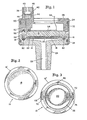
- Figure 1 is a cross-sectional view of the liquid-to-liquid transducer, showing two non-conductive plates 12 and 14 which form the heart of the transducer.
- the plates 12 and 14 may be made of any suitable insulating material which has low hysteresis and good stability. Typical materials which may be used include ceramic materials or glass. Operative embodiments have been made utilizing aluminum oxide, with the plates 12 and 14 being circular in their configuration.
- the two plates 12 and 14 could both be relatively thin so that they could act as diaphragms, or, as shown in Figure 1, the plate 12 may be relatively thick, while the plate 14 may be very thin so that it may act as a single diaphragm, and flex when there are changes in pressure across its surface.
- the diaphragm 14 may be in the order of 10 or 20 thousandths of an inch (250-500 pm) in thickness, where the diameter of the plates is in the order of 1-1/4 inch (3 cm).
- These three patents, which are assigned to the assignee of the present invention disclose and describe in some detail capacitive transducers of the type shown in Figure 1 of the present specification, but which are primarily intended for use in measuring the pressure of gases.
- the disclosures of the three above-identified U.S. patents are hereby incorporated by reference.
- the two insulating plates 12 and 14 are spaced apart and sealed together by a peripheral layer of glass frit 16.
- the glass frit may be made of glass particles having two different melting points. With the firing of the glass frit being accomplished at a temperature intermediate the melting points of the two glasses included in the glass frit, the two plates 12 and 14 may be accurately spaced apart in accordance with the size of the particles included in the higher melting point glass frit.
- the spacing between the plates 12 and 14 may be in the order of from 1/2 of a thousandth of an inch up to about 20 thousandths of an inch (12,5500 pm), with a spacing of between one and two thousandths of an inch (25-50 um) being practical for many applications.
- the diaphragm 14 may be provided with a single large area substantially circular conductive coating 18, while the inner face of the thicker plate 12 may be provided with a central conductive coating 20 and an outer coaxial conductive coating 22 spaced around from the inner conductive area 20.
- the outer periphery 16' of the diaphragm 14, as shown in Figure 2, and the outer periphery 16" of the plate 12 as shown in Figure 3, are provided with a coating of glass frit, which is later fired to provide the seal 16 as shown in Figure 1.
- glass frit in paste form may be screened onto the peripheral areas 16' and 16" as shown in Figures 2 and 3, and may be dried at a temperature of, for example, 100 degrees F. to 120 degrees F. (37°-49°C), and later fired, with the two areas 16' and 16" in engagement with one another to form the seal 16 as shown in Figure 1.
- the conductive areas 14, 20 and 22 are normally prepared by screening conductive material in paste form onto the aluminum oxide surfaces, and then firing the plates at an elevated temperature, as noted above.
- the assembly includes two additional housing members 24 and 26 which happen to be made of aluminum but could also be formed of a high quality, high strength plastic, for example.
- the aluminum member 24 is provided with a central conduit 28 through which one of the liquids, the pressure of which is to be sensed, is applied to the diaphragm 14.
- An O-ring 30 is provided to seal the member 24 around the periphery of the outer surface of diaphragm 14.
- An outer cylindrical metal member 32 which may also be formed of aluminum, has its upper and lower edges deformed inwardly to hold the assembly including the housing members 24 and 26 in position and in engagement with the sensor 12,14.
- the two additional O-rings 34 and 36 seal the member 32 to the housing members 24 and 26.
- the housing member 26 is provided with threads 38 to which the second source of liquid, the pressure of which is to be measured, may be coupled.
- an insert 54 which holds the rubber bellows member 42 in place within the conduit 44 against the shoulder 46 of the housing member 26.
- the insert 40 is held firmly in place by the deformed outer edges 48 of the threaded fitting 38.
- the conduit 44 is coupled to the space between the plates 12 and 14 by the opening 50 in the housing member 26 and by the central opening 52 in the insert 54, which in turn is aligned with the opening 56 extending through the thicker plate 12 of the sensor.
- the insert 54 is sealed against the upper surface of the plate 12 by the O-ring 58, and is sealed to the housing member 26 around the opening 50 by the 0-ring 60.
- the entire space between the plates 12 and 14 and in the channels 44, 50, 52 and 56 is evacuated, and then a low viscosity silicon oil is drawn into this entire volume, to completely fill the space between plates 12 and 14 and the passageway up through to the area 44.
- the rubber bellows member 42 is then inserted, the clamping member 40 is tightly forced down on the periphery of the rubber bellows 42, and it is crimped into place by deformation of the lip 48. This step is taken because the very small spacing between plates 12 and 14 means that, if fluid were to be directly applied to the passageways 44, 50, 52 and 56, without prior evacuation, there would be many small air bubbles trapped within the space between plates 12 and 14.
- the unit may be installed, and the two liquids, the differential pressure of which is to be measured, are coupled to the threads 38 at the top of the unit and to the conduit 28 extending downwardly from the housing member 24.
- the outer surface of the downwardly extending portion of member 24 enclosing conduit 28 may also be threaded.
- the capacitance of the variable capacitor made up of the common conductive coating 18, and the central coating 20 on plate 12 will increase substantially, while the capacitance of the reference capacitor including the common plate 18 and the outer conductive coating 22 will only increase by a small amount.
- Connections to the circuit 64 which represents a hybrid electronic chip, extend from points 68 and 70 in Figure 3, with connections extending under the glass frit zone 16" along paths 72 and 74, respectively, to the conductive coatings 20, and 22. Small holes through the thicker plate 12 permit the passage of leads from points 68 and 70 up to the integrated circuit chip 64.
- the reference capacitor was principally a separate element, and it was not physically exposed to the fluid filled space between the plates of the sensor. Under these conditions, the ratio of the variable capacitance to the reference capacitance could change drastically with temperature, in view of the different conditions obtaining at the reference capacitor as compared with conditions at the variable capacitor. Accordingly, calibration of the pressure sensor would be most difficult.
- the reference and the variable capacitance are both located under identical conditions in contact with and spaced apart by the dielectric fluid, such departures from linearity and other related difficulties are avoided.
- Tests were performed using sensors substantially as shown and described hereinabove in connection with Figures 1 through 3 of the drawings, and the results of these tests are set forth in Table I and Table II which are set forth hereinbelow.
- five sensors were constructed and tested, and these sensors were initially tested prior to filling with silicon oil, and they were again tested after having been filled with silicon oil, with an initial set of tests at different pressures being run 24 hours after the sensors had been oil-filled, and a second set of tests having been run 24 hours later, about 48 hours after the sensors were filled with oil.
- the results as set forth in Tables I and II are the results of the averages of the tests conducted with the five test pressure sensors.
- the diaphragm 14 is shown in Figure 14 as being somewhat thicker than its actual thickness, and this is also true of the conductive coatings 18, 20 and 22.
- the liquid-to-liquid pressure transducer may be employed in chemical process systems where the difference in pressure between two closed chambers or volumes is to be measured.
- One typical application could be the monitoring of pressure across a filter, where the pressure builds up as the filter becomes charged with particles.
- the reference and the variable capacitor are of substantially equal areas and value, so that under zero differential pressure conditions, the ratio of the two capacitance values is nearly unity. This is convenient for the adjustment of the associated output electronic circuit, and for consistency when the transducers have different dielectric material between the plates.
- the present invention is not to be limited to that precisely as described hereinabove and as shown in the accompanying drawings. More specifically, instead of using a separate insert 54 as shown in Figure 1, such structure could be built into the member 26; instead of the circular plates of aluminum oxide which were actually used in the arrangements of Figures 1 through 3, square glass plates of the type shown in U.S. Patent No. 4,329,732, cited above, could be employed; and output circuits other than the arrangements as described in connection with the electronic chip 64 could be employed.
- the dimensions as included in the present disclosure may be varied, to accommodate the different pressure ranges which may be employed, and the different materials which may be utilized. Accordingly, the present invention is not limited to the structural arrangement precisely as shown and described hereinabove.
Landscapes
- Chemical & Material Sciences (AREA)
- Engineering & Computer Science (AREA)
- Ceramic Engineering (AREA)
- Physics & Mathematics (AREA)
- General Physics & Mathematics (AREA)
- Measuring Fluid Pressure (AREA)
Claims (11)
Applications Claiming Priority (2)
| Application Number | Priority Date | Filing Date | Title |
|---|---|---|---|
| US384510 | 1982-06-03 | ||
| US06/384,510 US4425799A (en) | 1982-06-03 | 1982-06-03 | Liquid capacitance pressure transducer technique |
Publications (3)
| Publication Number | Publication Date |
|---|---|
| EP0110992A1 EP0110992A1 (de) | 1984-06-20 |
| EP0110992A4 EP0110992A4 (de) | 1984-11-23 |
| EP0110992B1 true EP0110992B1 (de) | 1987-05-20 |
Family
ID=23517604
Family Applications (1)
| Application Number | Title | Priority Date | Filing Date |
|---|---|---|---|
| EP83902335A Expired EP0110992B1 (de) | 1982-06-03 | 1983-05-26 | Flüssigkeitsgefüllter differentieller kapazitiver druckwandler und verfahren zu seiner herstellung |
Country Status (5)
| Country | Link |
|---|---|
| US (1) | US4425799A (de) |
| EP (1) | EP0110992B1 (de) |
| JP (2) | JPS59500987A (de) |
| DE (1) | DE3371694D1 (de) |
| WO (1) | WO1983004308A1 (de) |
Families Citing this family (52)
| Publication number | Priority date | Publication date | Assignee | Title |
|---|---|---|---|---|
| US4617607A (en) * | 1985-12-10 | 1986-10-14 | Kavlico Corporation | High pressure capacitive transducer |
| JPS62174249U (de) * | 1986-04-24 | 1987-11-05 | ||
| US5051937A (en) * | 1986-05-05 | 1991-09-24 | Texas Instruments Incorporated | Low cost high precision sensor |
| US4774626A (en) * | 1986-05-05 | 1988-09-27 | Texas Instruments Incorporated | Pressure sensor with improved capacitive pressure transducer |
| US4951236A (en) * | 1986-05-05 | 1990-08-21 | Texas Instruments Incorporated | Low cost high precision sensor |
| US4982351A (en) * | 1986-05-05 | 1991-01-01 | Texas Instruments Incorporated | Low cost high precision sensor |
| US4716492A (en) * | 1986-05-05 | 1987-12-29 | Texas Instruments Incorporated | Pressure sensor with improved capacitive pressure transducer |
| US4730496A (en) * | 1986-06-23 | 1988-03-15 | Rosemount Inc. | Capacitance pressure sensor |
| FI872049A7 (fi) * | 1987-05-08 | 1988-11-09 | Vaisala Oy | Paineanturissa käytettävä kondensaattorirakenne. |
| FI84401C (fi) * | 1987-05-08 | 1991-11-25 | Vaisala Oy | Kapacitiv tryckgivarkonstruktion. |
| US4785669A (en) * | 1987-05-18 | 1988-11-22 | Mks Instruments, Inc. | Absolute capacitance manometers |
| USH606H (en) | 1987-11-27 | 1989-03-07 | Motorola, Inc. | Pressure sensor assembly |
| US5043841A (en) * | 1989-06-13 | 1991-08-27 | Bishop Robert P | High pressure transducer package |
| US4928376A (en) * | 1989-07-31 | 1990-05-29 | Motorola Inc. | Method for filling a cavity, such as a sensor cavity, with an incompressible fluid |
| DE4018638A1 (de) * | 1990-06-11 | 1991-12-12 | Schoppe & Faeser Gmbh | Druckmessumformer mit einem rotationssymmetrischen drucksensor aus keramik |
| US5224383A (en) * | 1991-06-14 | 1993-07-06 | Industrial Sensors, Inc. | Melt pressure measurement and the like |
| DE4213857C2 (de) * | 1992-04-27 | 1995-10-19 | Endress Hauser Gmbh Co | Vorrichtung zum Messen von Druck und Differenzdruck |
| US5233875A (en) * | 1992-05-04 | 1993-08-10 | Kavlico Corporation | Stable capacitive pressure transducer system |
| US5844769A (en) * | 1992-08-19 | 1998-12-01 | Navistar International Transportation Corp. | Exhaust pressure transducer |
| US5315877A (en) * | 1993-02-19 | 1994-05-31 | Kavlico Corporation | Low cost versatile pressure transducer |
| US5275054A (en) * | 1993-04-07 | 1994-01-04 | Kavlico Corporation | Rubber free fluid pressure transducer |
| US5444901A (en) * | 1993-10-25 | 1995-08-29 | United Technologies Corporation | Method of manufacturing silicon pressure sensor having dual elements simultaneously mounted |
| US5545594A (en) * | 1993-10-26 | 1996-08-13 | Yazaki Meter Co., Ltd. | Semiconductor sensor anodic-bonding process, wherein bonding of corrugation is prevented |
| US5827972A (en) * | 1993-11-02 | 1998-10-27 | Texas Instruments Incorporated | High pressure sensor apparatus with low cost compact packaging system |
| US5485345A (en) * | 1994-11-14 | 1996-01-16 | Texas Instruments Incorporated | Pressure transducer apparatus |
| US5499158A (en) * | 1994-11-14 | 1996-03-12 | Texas Instruments Incorporated | Pressure transducer apparatus with monolithic body of ceramic material |
| KR19990008150A (ko) * | 1996-03-07 | 1999-01-25 | 노무라마사나리 | 압력센서모듈 |
| US5741975A (en) * | 1996-07-31 | 1998-04-21 | Motorola, Inc. | Media isolated differential pressure sensor and fluid injection method |
| EP0862051A4 (de) * | 1996-09-19 | 1999-12-08 | Hokuriku Elect Ind | Kapazitiver druckwandler |
| US20040099061A1 (en) | 1997-12-22 | 2004-05-27 | Mks Instruments | Pressure sensor for detecting small pressure differences and low pressures |
| SE9704840D0 (sv) * | 1997-12-22 | 1997-12-22 | Cecap Ab | Tryckgivare för detektering av små tryckdifferenser och låga tryck |
| JP2000009569A (ja) * | 1998-06-26 | 2000-01-14 | Denso Corp | 圧力センサの製造方法 |
| US6425291B1 (en) | 1999-07-01 | 2002-07-30 | Endress + Hauser Gmbh + Co. | Relative-pressure sensor having a gas-filled bellows |
| EP1065488B1 (de) * | 1999-07-01 | 2007-02-28 | Endress + Hauser GmbH + Co. KG | Relativdrucksensor |
| US6148674A (en) * | 1999-09-15 | 2000-11-21 | Park; Kyong M. | Shielded capacitive pressure sensor |
| US7152478B2 (en) * | 2000-07-20 | 2006-12-26 | Entegris, Inc. | Sensor usable in ultra pure and highly corrosive environments |
| US6612175B1 (en) | 2000-07-20 | 2003-09-02 | Nt International, Inc. | Sensor usable in ultra pure and highly corrosive environments |
| DE10043630A1 (de) * | 2000-09-01 | 2002-03-14 | Endress Hauser Gmbh Co | Druckmeßzelle |
| FR2818676B1 (fr) * | 2000-12-27 | 2003-03-07 | Freyssinet Int Stup | Procede de demontage d'un cable de precontrainte et dispositif pour la mise en oeuvre |
| US6993973B2 (en) * | 2003-05-16 | 2006-02-07 | Mks Instruments, Inc. | Contaminant deposition control baffle for a capacitive pressure transducer |
| US20080287813A1 (en) * | 2004-03-30 | 2008-11-20 | Eidgenossische Technische Hochschule Zurich | Blood Pressure Monitoring Device and Methods for Making and for Using Such a Device |
| US7201057B2 (en) * | 2004-09-30 | 2007-04-10 | Mks Instruments, Inc. | High-temperature reduced size manometer |
| US7137301B2 (en) * | 2004-10-07 | 2006-11-21 | Mks Instruments, Inc. | Method and apparatus for forming a reference pressure within a chamber of a capacitance sensor |
| US7141447B2 (en) * | 2004-10-07 | 2006-11-28 | Mks Instruments, Inc. | Method of forming a seal between a housing and a diaphragm of a capacitance sensor |
| US7204150B2 (en) | 2005-01-14 | 2007-04-17 | Mks Instruments, Inc. | Turbo sump for use with capacitive pressure sensor |
| DE102007001445A1 (de) * | 2007-01-03 | 2008-07-10 | Vega Grieshaber Kg | Abdichteinrichtung zum Verschließen eines Druckmesszellengehäuses, Druckmesszelleneinrichtung bzw. Druckmessvorrichtung damit |
| US7775118B2 (en) * | 2008-04-24 | 2010-08-17 | Custom Sensors & Technologies, Inc. | Sensor element assembly and method |
| US8468894B2 (en) | 2009-11-02 | 2013-06-25 | Vega Grieshaber Kg | Measuring cell and a method of use therefor |
| DE102009051611A1 (de) * | 2009-11-02 | 2011-05-05 | Vega Grieshaber Kg | Messzelle |
| DE102009051613A1 (de) * | 2009-11-02 | 2011-05-05 | Vega Grieshaber Kg | Messzelle |
| US8863580B2 (en) * | 2011-05-05 | 2014-10-21 | Rosemount Inc. | Process fluid pressure transmitter with replaceable atmospheric vent filter |
| US11346698B2 (en) * | 2019-06-21 | 2022-05-31 | Sporian Microsystems, Inc. | Compact pressure and flow sensors for very high temperature and corrosive fluids |
Family Cites Families (13)
| Publication number | Priority date | Publication date | Assignee | Title |
|---|---|---|---|---|
| GB1563894A (en) * | 1976-03-12 | 1980-04-02 | Kavlico Corp | Capacitive pressure transducer and method for making same |
| US4064550A (en) * | 1976-03-22 | 1977-12-20 | Hewlett-Packard Company | High fidelity pressure transducer |
| US4207604A (en) | 1976-12-02 | 1980-06-10 | Kavlico Corporation | Capacitive pressure transducer with cut out conductive plate |
| US4120206A (en) | 1977-01-17 | 1978-10-17 | Rosemount Inc. | Differential pressure sensor capsule with low acceleration sensitivity |
| JPS53106180A (en) * | 1977-02-28 | 1978-09-14 | Hokushin Electric Works | Different pressure transmitting instrument |
| JPS5829862B2 (ja) | 1977-05-14 | 1983-06-25 | 富士電機株式会社 | 圧力測定装置 |
| JPS5436984A (en) * | 1977-08-30 | 1979-03-19 | Fuji Electric Co Ltd | Pressure measuring apparatus |
| CA1091059A (en) * | 1978-02-10 | 1980-12-09 | Thomas M. Dauphinee | Apparatus for measuring barometric pressure |
| US4380041A (en) | 1978-09-25 | 1983-04-12 | Motorola Inc. | Capacitor pressure transducer with housing |
| JPS5581997A (en) * | 1978-12-14 | 1980-06-20 | Nippon Shiirudo Engineering Kk | Method of building culvert in stable fluid under ground |
| US4227418A (en) | 1979-09-24 | 1980-10-14 | Fischer & Porter Company | Capacitive pressure transducer |
| JPS5679225A (en) * | 1979-11-30 | 1981-06-29 | Yokogawa Hokushin Electric Corp | Structure of differential pressure gauge |
| US4370890A (en) * | 1980-10-06 | 1983-02-01 | Rosemount Inc. | Capacitive pressure transducer with isolated sensing diaphragm |
-
1982
- 1982-06-03 US US06/384,510 patent/US4425799A/en not_active Expired - Lifetime
-
1983
- 1983-05-26 DE DE8383902335T patent/DE3371694D1/de not_active Expired
- 1983-05-26 WO PCT/US1983/000872 patent/WO1983004308A1/en not_active Ceased
- 1983-05-26 JP JP58502288A patent/JPS59500987A/ja active Pending
- 1983-05-26 EP EP83902335A patent/EP0110992B1/de not_active Expired
-
1992
- 1992-07-20 JP JP056195U patent/JPH0682535U/ja active Pending
Also Published As
| Publication number | Publication date |
|---|---|
| US4425799A (en) | 1984-01-17 |
| JPS59500987A (ja) | 1984-05-31 |
| EP0110992A1 (de) | 1984-06-20 |
| WO1983004308A1 (en) | 1983-12-08 |
| EP0110992A4 (de) | 1984-11-23 |
| JPH0682535U (ja) | 1994-11-25 |
| DE3371694D1 (en) | 1987-06-25 |
Similar Documents
| Publication | Publication Date | Title |
|---|---|---|
| EP0110992B1 (de) | Flüssigkeitsgefüllter differentieller kapazitiver druckwandler und verfahren zu seiner herstellung | |
| US6295875B1 (en) | Process pressure measurement devices with improved error compensation | |
| US4168518A (en) | Capacitor transducer | |
| US4177496A (en) | Capacitive pressure transducer | |
| EP0164413B1 (de) | Druckwandler | |
| US4388668A (en) | Capacitive pressure transducer | |
| US4336567A (en) | Differential pressure transducer | |
| EP0024946B1 (de) | Herstellungsverfahren für variable kapazitive Wandler | |
| US6520020B1 (en) | Method and apparatus for a direct bonded isolated pressure sensor | |
| US4735098A (en) | Dual diaphragm differential pressure transducer | |
| US4572000A (en) | Pressure sensor with a substantially flat overpressure stop for the measuring diaphragm | |
| US4386453A (en) | Method for manufacturing variable capacitance pressure transducers | |
| US4599906A (en) | Remote probe differential pressure transducer | |
| EP1407464A1 (de) | Elektromechanischer mikrosensor | |
| US4680971A (en) | Dual diaphragm differential pressure transducer | |
| EP0198018A1 (de) | Kapazitive sensorzelle von sprödem material | |
| US5275054A (en) | Rubber free fluid pressure transducer | |
| US5034848A (en) | Low pressure sensor | |
| US6499352B2 (en) | Pressure measuring cell | |
| JPS5855833A (ja) | 差圧測定装置 | |
| WO1991015742A2 (en) | Pressure sensing capacitor, and transducer | |
| CN113091992A (zh) | 高量程压差传感器 | |
| JP2006133104A (ja) | 静電容量式圧力センサ |
Legal Events
| Date | Code | Title | Description |
|---|---|---|---|
| PUAI | Public reference made under article 153(3) epc to a published international application that has entered the european phase |
Free format text: ORIGINAL CODE: 0009012 |
|
| 17P | Request for examination filed |
Effective date: 19840202 |
|
| AK | Designated contracting states |
Designated state(s): DE FR GB SE |
|
| GRAA | (expected) grant |
Free format text: ORIGINAL CODE: 0009210 |
|
| AK | Designated contracting states |
Kind code of ref document: B1 Designated state(s): DE FR GB SE |
|
| REF | Corresponds to: |
Ref document number: 3371694 Country of ref document: DE Date of ref document: 19870625 |
|
| ET | Fr: translation filed | ||
| PLBI | Opposition filed |
Free format text: ORIGINAL CODE: 0009260 |
|
| 26 | Opposition filed |
Opponent name: HARTMANN & BRAUN AG Effective date: 19880220 |
|
| PLBN | Opposition rejected |
Free format text: ORIGINAL CODE: 0009273 |
|
| STAA | Information on the status of an ep patent application or granted ep patent |
Free format text: STATUS: OPPOSITION REJECTED |
|
| 27O | Opposition rejected |
Effective date: 19900401 |
|
| EAL | Se: european patent in force in sweden |
Ref document number: 83902335.5 |
|
| PGFP | Annual fee paid to national office [announced via postgrant information from national office to epo] |
Ref country code: SE Payment date: 19970421 Year of fee payment: 15 Ref country code: FR Payment date: 19970421 Year of fee payment: 15 |
|
| PGFP | Annual fee paid to national office [announced via postgrant information from national office to epo] |
Ref country code: GB Payment date: 19970425 Year of fee payment: 15 |
|
| PGFP | Annual fee paid to national office [announced via postgrant information from national office to epo] |
Ref country code: DE Payment date: 19970428 Year of fee payment: 15 |
|
| PG25 | Lapsed in a contracting state [announced via postgrant information from national office to epo] |
Ref country code: GB Free format text: LAPSE BECAUSE OF NON-PAYMENT OF DUE FEES Effective date: 19980526 |
|
| PG25 | Lapsed in a contracting state [announced via postgrant information from national office to epo] |
Ref country code: SE Free format text: LAPSE BECAUSE OF NON-PAYMENT OF DUE FEES Effective date: 19980527 |
|
| PG25 | Lapsed in a contracting state [announced via postgrant information from national office to epo] |
Ref country code: FR Free format text: LAPSE BECAUSE OF NON-PAYMENT OF DUE FEES Effective date: 19980531 |
|
| GBPC | Gb: european patent ceased through non-payment of renewal fee |
Effective date: 19980526 |
|
| EUG | Se: european patent has lapsed |
Ref document number: 83902335.5 |
|
| PG25 | Lapsed in a contracting state [announced via postgrant information from national office to epo] |
Ref country code: DE Free format text: LAPSE BECAUSE OF NON-PAYMENT OF DUE FEES Effective date: 19990302 |
|
| REG | Reference to a national code |
Ref country code: FR Ref legal event code: ST |