EP0110458B1 - Tube à rayons cathodiques muni d'un écran luminescent, procédé pour la fabrication d'un écran destiné à un tel tube et tube image de télévision à projection muni d'un tel écran - Google Patents
Tube à rayons cathodiques muni d'un écran luminescent, procédé pour la fabrication d'un écran destiné à un tel tube et tube image de télévision à projection muni d'un tel écran Download PDFInfo
- Publication number
- EP0110458B1 EP0110458B1 EP19830201591 EP83201591A EP0110458B1 EP 0110458 B1 EP0110458 B1 EP 0110458B1 EP 19830201591 EP19830201591 EP 19830201591 EP 83201591 A EP83201591 A EP 83201591A EP 0110458 B1 EP0110458 B1 EP 0110458B1
- Authority
- EP
- European Patent Office
- Prior art keywords
- screen
- support
- layer
- tube
- cells
- Prior art date
- Legal status (The legal status is an assumption and is not a legal conclusion. Google has not performed a legal analysis and makes no representation as to the accuracy of the status listed.)
- Expired
Links
- 238000000034 method Methods 0.000 title claims description 21
- 238000004519 manufacturing process Methods 0.000 title claims description 6
- 239000000463 material Substances 0.000 claims description 42
- 239000004922 lacquer Substances 0.000 claims description 26
- 238000010894 electron beam technology Methods 0.000 claims description 19
- 229910052751 metal Inorganic materials 0.000 claims description 11
- 239000002184 metal Substances 0.000 claims description 11
- 230000005855 radiation Effects 0.000 claims description 11
- 239000011521 glass Substances 0.000 claims description 8
- 238000000151 deposition Methods 0.000 claims description 6
- 230000005684 electric field Effects 0.000 claims description 6
- 239000011810 insulating material Substances 0.000 claims description 5
- 230000003287 optical effect Effects 0.000 claims description 5
- 230000004075 alteration Effects 0.000 claims description 4
- 238000001035 drying Methods 0.000 claims description 4
- 238000001962 electrophoresis Methods 0.000 claims description 4
- 238000010438 heat treatment Methods 0.000 claims description 4
- 239000006089 photosensitive glass Substances 0.000 claims description 3
- 238000005245 sintering Methods 0.000 claims description 3
- 239000002826 coolant Substances 0.000 claims description 2
- 239000012777 electrically insulating material Substances 0.000 claims description 2
- 239000011347 resin Substances 0.000 claims description 2
- 229920005989 resin Polymers 0.000 claims description 2
- 230000000379 polymerizing effect Effects 0.000 claims 1
- RHAXKFFKGZJUOE-UHFFFAOYSA-N 7-acetyl-6-ethyl-3,5,8-trihydroxy-9,10-dioxoanthracene-1,2-dicarboxylic acid Chemical compound O=C1C2=CC(O)=C(C(O)=O)C(C(O)=O)=C2C(=O)C2=C1C(O)=C(CC)C(C(C)=O)=C2O RHAXKFFKGZJUOE-UHFFFAOYSA-N 0.000 description 18
- 229920000297 Rayon Polymers 0.000 description 6
- 239000002964 rayon Substances 0.000 description 6
- 238000004020 luminiscence type Methods 0.000 description 5
- 239000007788 liquid Substances 0.000 description 4
- CSCPPACGZOOCGX-UHFFFAOYSA-N Acetone Chemical compound CC(C)=O CSCPPACGZOOCGX-UHFFFAOYSA-N 0.000 description 3
- 241001080024 Telles Species 0.000 description 3
- 230000005540 biological transmission Effects 0.000 description 3
- 238000005119 centrifugation Methods 0.000 description 3
- 238000001816 cooling Methods 0.000 description 3
- 241000447437 Gerreidae Species 0.000 description 2
- 238000010276 construction Methods 0.000 description 2
- 239000000110 cooling liquid Substances 0.000 description 2
- 230000003247 decreasing effect Effects 0.000 description 2
- 230000008021 deposition Effects 0.000 description 2
- 238000004090 dissolution Methods 0.000 description 2
- 238000005868 electrolysis reaction Methods 0.000 description 2
- 229920001220 nitrocellulos Polymers 0.000 description 2
- 238000007738 vacuum evaporation Methods 0.000 description 2
- LFQSCWFLJHTTHZ-UHFFFAOYSA-N Ethanol Chemical compound CCO LFQSCWFLJHTTHZ-UHFFFAOYSA-N 0.000 description 1
- 239000000020 Nitrocellulose Substances 0.000 description 1
- 229910018487 Ni—Cr Inorganic materials 0.000 description 1
- 229910006404 SnO 2 Inorganic materials 0.000 description 1
- 229910052782 aluminium Inorganic materials 0.000 description 1
- XAGFODPZIPBFFR-UHFFFAOYSA-N aluminium Chemical compound [Al] XAGFODPZIPBFFR-UHFFFAOYSA-N 0.000 description 1
- 239000000919 ceramic Substances 0.000 description 1
- VNNRSPGTAMTISX-UHFFFAOYSA-N chromium nickel Chemical compound [Cr].[Ni] VNNRSPGTAMTISX-UHFFFAOYSA-N 0.000 description 1
- 239000011248 coating agent Substances 0.000 description 1
- 238000000576 coating method Methods 0.000 description 1
- 239000000470 constituent Substances 0.000 description 1
- 238000010411 cooking Methods 0.000 description 1
- 239000012809 cooling fluid Substances 0.000 description 1
- 229910052802 copper Inorganic materials 0.000 description 1
- 239000013078 crystal Substances 0.000 description 1
- 230000007547 defect Effects 0.000 description 1
- 238000009792 diffusion process Methods 0.000 description 1
- 238000007599 discharging Methods 0.000 description 1
- 230000005284 excitation Effects 0.000 description 1
- 239000012530 fluid Substances 0.000 description 1
- 229910052737 gold Inorganic materials 0.000 description 1
- 230000017525 heat dissipation Effects 0.000 description 1
- 230000020169 heat generation Effects 0.000 description 1
- 238000009434 installation Methods 0.000 description 1
- 229910052759 nickel Inorganic materials 0.000 description 1
- 239000002245 particle Substances 0.000 description 1
- 230000035515 penetration Effects 0.000 description 1
- 238000007750 plasma spraying Methods 0.000 description 1
- 238000006116 polymerization reaction Methods 0.000 description 1
- 239000000843 powder Substances 0.000 description 1
- 229910052709 silver Inorganic materials 0.000 description 1
- 238000005507 spraying Methods 0.000 description 1
- 239000000758 substrate Substances 0.000 description 1
- 239000008399 tap water Substances 0.000 description 1
- 235000020679 tap water Nutrition 0.000 description 1
- 239000010409 thin film Substances 0.000 description 1
- 239000012808 vapor phase Substances 0.000 description 1
Images


Classifications
-
- H—ELECTRICITY
- H01—ELECTRIC ELEMENTS
- H01J—ELECTRIC DISCHARGE TUBES OR DISCHARGE LAMPS
- H01J9/00—Apparatus or processes specially adapted for the manufacture, installation, removal, maintenance of electric discharge tubes, discharge lamps, or parts thereof; Recovery of material from discharge tubes or lamps
- H01J9/20—Manufacture of screens on or from which an image or pattern is formed, picked up, converted or stored; Applying coatings to the vessel
- H01J9/22—Applying luminescent coatings
- H01J9/227—Applying luminescent coatings with luminescent material discontinuously arranged, e.g. in dots or lines
- H01J9/2271—Applying luminescent coatings with luminescent material discontinuously arranged, e.g. in dots or lines by photographic processes
-
- H—ELECTRICITY
- H01—ELECTRIC ELEMENTS
- H01J—ELECTRIC DISCHARGE TUBES OR DISCHARGE LAMPS
- H01J29/00—Details of cathode-ray tubes or of electron-beam tubes of the types covered by group H01J31/00
- H01J29/02—Electrodes; Screens; Mounting, supporting, spacing or insulating thereof
- H01J29/10—Screens on or from which an image or pattern is formed, picked up, converted or stored
- H01J29/18—Luminescent screens
- H01J29/24—Supports for luminescent material
Definitions
- the present invention relates to a cathode ray tube provided with a luminescent screen comprising a support having luminescent material, support which is provided with a configuration of cells filled with luminescent material, cells which have the form of juxtaposed tubes extending in the support and whose walls are reflective.
- the invention also relates to a method for manufacturing a screen intended for such a tube and to the tube for projecting television images provided with such a screen.
- Obtaining a high gloss is one of the qualities sought for a cathode ray tube screen, in particular when this screen is that of a projection television picture tube. It is well known that greater brightness of a tube can be obtained by increasing the thickness of the luminescent layer constituting the screen and simultaneously giving greater energy (greater beam current and / or more accelerating voltage high) to the electron beam ensuring the bombardment of said layer. However, this increase in brightness is accompanied by an increase in the diameter of the light spot on the screen. This is due to the lateral scattering of the light generated in the insulating layer. This increase in the diameter of the light spot results in a notable reduction in the contrast and the resolution of the image represented.
- Such a structure has several disadvantages.
- the beam electrons make a notable angle with the axes of the tubular cells of the screen, the beam electrons only bombard a small part of the luminescent material due to a weak penetration of the beam or to a phenomenon of shading by the walls of these cells. Part of the luminescent material is not exposed to electron bombardment. It also follows that the bombardment of the luminescent material on the surface of the screen is not uniform and that the luminescent material in each of the cells is used incompletely. As a result, the resolution, contrast and maximum image brightness are not uniform over the entire surface of the screen. In addition, the heat dissipation is not sufficient when the heat generation is too high, which is among other things the case of tubes intended for the projection of television images.
- the invention aims to increase the brightness of the image without reducing the resolution and the contrast, in the case of flat screens, or concave or convex screens.
- the invention also aims to make the resolution, contrast and maximum image brightness of such a tube uniform over the entire screen surface.
- Another object of the invention consists in improving the brightness of the screen by providing the screen with means preventing an increase in the temperature of the layer caused by the heat developed in the luminescent layer, so that the luminescence of said layer is not reduced.
- a luminescent screen of the kind described in the first paragraph is characterized in that the axes of the cells converge essentially towards the center of deflection of the electron beam.
- the screen operates in transmission, that is to say that the luminescence light is emitted through the support.
- the support comprises two glass panes, which are transparent to light and which are both with faces parallel and parallel to each other and constitute a double wall in the envelope of the tube, the cells of the screen opening out. on the inner wall of the tube support, the same cells being provided at this outlet with a transparent metallic layer to electrons and reflecting light, the double wall being provided with means for admitting and discharging a cooling fluid circulating between the two glass panes of the double wall.
- the screen and its support are flat or even concave on the side of the electronic scanning or else, the walls of the cells are highly conductive or not of heat and in particular metallic.
- the screen operates in reflection.
- the support is opaque, the cells of the screen emitting luminescence light on the receiving side of the electron beam on the screen, a tube which is provided with means for projecting images, while the support is provided means for cooling said screen.
- the screen and its support are planar or convex on the side of the incidence of the electron beam on the screen.
- the walls of the cells can be highly conductive of heat and in particular metallic.
- the associated optical system comprises, centered on the axis of the tube, a concave mirror facing the screen and a plate for correcting the aberrations of this mirror placed behind the screen.
- the electrolytic growth of metal walls in the empty lacquer parts of said first layer is replaced by the growth of walls of electrically insulating material by the use of known techniques of the cathaphoresis or anaphoresis genus, transport grains of said insulating material on the support taking place using electrostatic forces resulting from the electric field established between the screen support and an electrode parallel to the free surface of said first layer, the growth being followed by sintering at high temperature to improve the mechanical strength of the deposit.
- This wall constituent material is for example Si0 2 , AI 2 0 3 , MgO or even better, to improve the thermal conductivity, BeO.
- the screen support is made of a material which is itself photosensitive in the field of ultraviolet radiation, which avoids having to cover it with a layer of lacquer sensitive to ultraviolet radiation.
- This material is for example a photosensitive glass and the process proceeds practically in the same way, except that the cells are formed directly in the support without the need for growth by electrolysis or other of the walls of these cells.
- the point of convergence of the axes of the cells on the axis of the screen is coincident, during the positioning of said screen in the future cathode ray tube, with the center of deflection of the scanning electron beam of said tube.
- This latter embodiment leads directly to devices which can be used for the projection on the screen, outside the tube, of television images.
- Figure 1 shows how the relative brightness of a layer of luminescent material varies as a function of temperature. For a temperature of 80 ° C, the gloss has decreased by 50%. It is for this reason that to obtain a high gloss it is necessary to remove from the luminescent material the heat released by an electron bombardment.
- FIG. 2 which relates to a cathode ray tube according to the prior art, with a flat screen represented in section by a plane of symmetry, indicates under the reference numeral 11, the envelope of the tube with its conical part 12 and the neck 13.
- This neck is provided with an electronic cannon and a deflection system, both of which are described below in FIG. 4.
- the electron beam is 10.
- the electron beams of the electron gun whose trajectories are supposed to be rectilinear come, after deflection, apparently from point A, which is called the center of deflection of the beam.
- the electron beams reach the screen 14 which is deposited on a wall of the envelope 11 of said tube.
- this screen is provided with cells in the form of small tubes, of which, for the simplicity of the drawing, only three are shown, namely under the numbers 15 , 16.17.
- the screen is lined inside the cathode ray tube with a multitude of these small tubes juxtaposed to each other.
- the axes of these tubes 18, 19, 21 respectively are parallel to each other and to the axis of the cathode ray tube itself 21.
- the section of these tubes is substantially equal to that on the screen of the scanning beam 10.
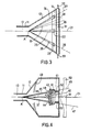
- Figure 3 relates to a cathode ray tube according to the invention.
- the screen 14 which is deposited on the inner wall of the casing 11, is produced in another way. It always includes cells filled in the form of juxtaposed tubes of small diameter but whose axes are not parallel to each other. To simplify the figure, only three of these tubes, in particular 28, 22, 23 are shown.
- the electron beam is deflected in three directions 24, 25 and 26.
- These tubes are in the form of a cone or a cylinder and have axes 27, 21, 29 which are oriented so that they pass practically by the center of curvature A. It follows that all the luminescent material contained in the tubes is excited by the bombardment of electrons. In addition, the luminescent material is cooled.
- the envelope of the tube is provided with a double wall 31, in which a coolant circulates, the admission of which is ensured by the tube 32 and the evacuation by the tube 33.
- FIG. 4 relates to a cathode ray tube for projecting television images in the case of a convex screen associated with its projection optics.
- FIG. 4 we find the elements 11, 12, 13 and 21 of FIG. 1.
- This tube consists of an envelope 11 formed from the neck of the tube 13, of length 250 mm and diameter 36 mm, and of the cone of the tube 12 of length 150 mm and diameter of 150 mm at its widest part.
- this last part although generally conical over its entire length, may have a shorter conical part followed by a cylindrical part.
- an electron gun composed of a thermionic cathode with indirect heating and a number of cylindrical anodes 110 making it possible to accelerate the electrons.
- the focusing is of the electrostatic or magnetic type using the external coils.
- the tube has deflection coils 120 for scanning along the X and Y axes.
- the screen 41 has a convex shape and is applied to a screen support 40 disposed in the cone of the tube. As in the first embodiment, this screen is provided with cells filled with luminescent material.
- These cells including for the simplicity of the figure, only three are represented, namely 42, 43, and 44, are small tubes in the form of a truncated cone or cylinder whose axes respectively 45, 21, 47 pass practiqeument through the center of deflection A.
- the directions of the beam of electrons according to which the bombardment of these tubes takes place are 35, 36, 37.
- the section of the electron beam in the convex plane 48 of the screen turns out to be practically equal to the right of each tube to the section of said tube in the same plane.
- maximum excitation of the luminescent material in the tube is ensured.
- the cathode ray tube is provided with an optic for projecting the screen of the face 48.
- This optic is for example an optic of the known art known as Schmidt, which is constituted by the concave mirror 49, placed on the inner wall of the tube and by the plate 50 for the aberration correction and which is placed at the entrance of the tube behind the screen.
- the dimensions of the rectangular screen 41 are 36 mm x 48 mm.
- the radius of curvature of the convex screen is equal to half the radius of curvature of mirror 49.
- This mirror 49 is pierced in its center with an opening of 35 mm in diameter to allow the electron beam to wait for the 'screen.
- the beam current of the tube is approximately 2m A peak for a high voltage of up to 50 K. or so, which represents 100 watts dissipated on the screen.
- a cooling device In order to cool the screen, as in the first embodiment, it is provided with a cooling device.
- This comprises a cooling liquid circulation system in a double wall consisting of the support 40 of the screen and a wall 51, which is welded in a watertight manner to the periphery of the support 40, the admission and evacuation of liquid being effected by means of the tubes 52 and 53 opening towards the outside of the envelope 11 of the tube.
- the cooling circuit using a fluid at a temperature of 25 ° C, for example tap water, with a flow rate of 1.5 liters / minute makes it possible to ensure that the temperature of the screen does not exceed 100 ° C.
- the manufacturing process will successively use these two characteristics to proceed with the very development of the screen and the tube.
- the use of the optics associated with the tube to participate in the steps of the method makes it possible to have an image where the different possible optical defects are reduced (aberrations, convergence, etc.).
- the luminescent material must have a massive structure, its deposition can be carried out by epitaxial growth in the vapor phase, or even by means of a cathodic or plasma spraying or even by spraying of liquid.
- the substrate In the case of a screen used in transmission, the substrate must be transparent, for example made of glass or crystals.
- the first of the preceding steps is then modified, the metal deposit then being an electrically conductive and optically transparent oxide deposit.
- Deposits of SnO 2 or In 2 0 3 of around 300 Angtroms of thickness and resistivity of around 400 ohms / square correspond to this use.
- a new stage then presents itself: on the face where the luminescent product appears, a thin film of nitrocellulose is deposited, in liquid medium, on which, by vacuum evaporation, a thin metallic layer of 1000 A is deposited, for example aluminum .
- Heat treatment is carried out with air, at around 350 ° C., in order to burn the thin nitrocellulose film so that the thin metal layer remains alone, which makes it possible to obtain a configuration of sealed cells filled with luminescent product.
- This thin metallic layer is transparent to the electrons in the electron beam but reflects the light from the luminescent product when the latter emits its luminescence light.
- a second variant after obtaining the hollow parts 84 to 88 of FIG. 6, these are filled by cathaphoresis or anaphoresis of an insulating material using the electrostatic forces resulting from an electric field applied between the support screen 40 and an electrode parallel to 48 and located between 48 and point A.
- the growth of the latter is followed by sintering at high temperature, the process then proceeds as follows the first variant.
- the material used, constituting these walls is for example Si0 2 , AlpO 3 , MgO or, even better, to improve the thermal conductivity, BeO.
- the screen support 40 is not necessarily electrically conductive. It is thicker than in FIG. 6. It has for example the thickness of 41 and, moreover, it is made up of a material itself photosensitive to ultraviolet rays, so that it is not necessary to cover with a layer of lacquer sensitive to ultraviolet radiation. This material is for example a photosensitive glass. After forming a mask on the surface of the glass, the parts of which transparent to ultraviolet rays correspond to the openings of the desired alveoli, the latter is exposed using a point source of ultraviolet radiation which, just as before, is placed at point A, the process taking place in a similar manner except that the cells are formed directly in the support without the need for growth by electrolysis or other of the walls of these cells.
Landscapes
- Engineering & Computer Science (AREA)
- Manufacturing & Machinery (AREA)
- Cathode-Ray Tubes And Fluorescent Screens For Display (AREA)
Applications Claiming Priority (2)
| Application Number | Priority Date | Filing Date | Title |
|---|---|---|---|
| FR8218919 | 1982-11-10 | ||
| FR8218919A FR2535896A1 (fr) | 1982-11-10 | 1982-11-10 | Perfectionnement aux ecrans de luminophore de tube electronique du genre tube cathodique, procede de fabrication d'un tel ecran perfectionne et tube notamment pour projection d'images de television muni d'un tel ecran |
Publications (2)
| Publication Number | Publication Date |
|---|---|
| EP0110458A1 EP0110458A1 (fr) | 1984-06-13 |
| EP0110458B1 true EP0110458B1 (fr) | 1987-04-01 |
Family
ID=9279097
Family Applications (1)
| Application Number | Title | Priority Date | Filing Date |
|---|---|---|---|
| EP19830201591 Expired EP0110458B1 (fr) | 1982-11-10 | 1983-11-08 | Tube à rayons cathodiques muni d'un écran luminescent, procédé pour la fabrication d'un écran destiné à un tel tube et tube image de télévision à projection muni d'un tel écran |
Country Status (4)
| Country | Link |
|---|---|
| EP (1) | EP0110458B1 (enExample) |
| JP (1) | JPS5999647A (enExample) |
| DE (1) | DE3370718D1 (enExample) |
| FR (1) | FR2535896A1 (enExample) |
Families Citing this family (1)
| Publication number | Priority date | Publication date | Assignee | Title |
|---|---|---|---|---|
| US4626739A (en) * | 1984-05-10 | 1986-12-02 | At&T Bell Laboratories | Electron beam pumped mosaic array of light emitters |
Family Cites Families (4)
| Publication number | Priority date | Publication date | Assignee | Title |
|---|---|---|---|---|
| US3089956A (en) * | 1953-07-10 | 1963-05-14 | Westinghouse Electric Corp | X-ray fluorescent screen |
| US2996634A (en) * | 1958-08-20 | 1961-08-15 | American Optical Corp | Cathode ray tubes |
| DE1414684B2 (de) * | 1961-02-27 | 1972-04-13 | American Optical Corp., Southbridge, Mass. (V.StA.) | Bildroehre mit leuchtschirm |
| JPS493295B1 (enExample) * | 1970-03-23 | 1974-01-25 |
-
1982
- 1982-11-10 FR FR8218919A patent/FR2535896A1/fr active Granted
-
1983
- 1983-11-08 EP EP19830201591 patent/EP0110458B1/fr not_active Expired
- 1983-11-08 DE DE8383201591T patent/DE3370718D1/de not_active Expired
- 1983-11-09 JP JP20927983A patent/JPS5999647A/ja active Pending
Also Published As
| Publication number | Publication date |
|---|---|
| FR2535896A1 (fr) | 1984-05-11 |
| JPS5999647A (ja) | 1984-06-08 |
| FR2535896B1 (enExample) | 1985-01-18 |
| DE3370718D1 (en) | 1987-05-07 |
| EP0110458A1 (fr) | 1984-06-13 |
Similar Documents
| Publication | Publication Date | Title |
|---|---|---|
| EP0559550B1 (fr) | Tube intensificateur d'image, notamment radiologique, du type à galette de microcanaux | |
| FR2744564A1 (fr) | Corps de cathode, canon a electrons, et tube a rayons cathodiques, utilisant un emetteur ferroelectrique | |
| FR2926668A1 (fr) | Source d'electrons a base d'emetteurs de champs pour radiographie multipoint. | |
| FR2675306A1 (fr) | Structure de cathode froide a film mince et dispositif utilisant cette cathode. | |
| FR2791808A1 (fr) | Dispositif d'affichage a plasma et procede de fabrication d'une couche de dielectrique comportant une partie ou un champ electrique est concentre | |
| EP0554145B1 (fr) | Tube intensificateur d'image, notamment du type à focalisation de proximité | |
| FR2530851A1 (fr) | Appareil de visualisation plan pour televiseurs et terminaux | |
| FR2735900A1 (fr) | Source d'electrons du type a emission de champ et procede pour la fabriquer | |
| EP0110458A1 (fr) | Tube à rayons cathodiques muni d'un écran luminescent, procédé pour la fabrication d'un écran destiné à un tel tube et tube image de télévision à projection muni d'un tel écran | |
| FR2724041A1 (fr) | Ecran plat de visualisation a haute tension inter-electrodes | |
| EP0044239B1 (fr) | Tube intensificateur d'images à micro-canaux et ensemble de prise de vues comprenant un tel tube | |
| FR2647580A1 (fr) | Dispositif d'affichage electroluminescent utilisant des electrons guides et son procede de commande | |
| FR2459549A1 (fr) | Perfectionnement aux tubes de prises de vues de television du genre vidicon | |
| FR2844916A1 (fr) | Source de rayonnement x a foyer virtuel ou fictif | |
| EP0319402B1 (fr) | Utilisation d'un canon à électrons pour tube à rayonnement cathodique | |
| EP0228735B1 (fr) | Dispositif d'insolation pour la génération de masques | |
| FR2522196A1 (fr) | Tube a rayons cathodiques a aberration spherique reduite | |
| JPH03129642A (ja) | 陰極線管用カソードルミネツセントスクリーン | |
| EP0143714B1 (fr) | Ecran luminescent et procédé de fabrication d'un tel écran | |
| CH556605A (fr) | Tube video-cathodique. | |
| EP0269472B1 (fr) | Tube de prise de vue muni d'un dispositif de polarisation lumineuse | |
| FR2694130A1 (fr) | Tube cathodique en couleurs. | |
| US4150165A (en) | Lead monoxide target and method of manufacturing same | |
| FR2604560A1 (fr) | Tube electrostatique obturateur muni d'ouvertures de collimation pour photographie a haute vitesse | |
| WO1986001937A1 (fr) | Tube a image a sortie video, systeme de prise de vue utilisant un tel tube et procede de fonctionnement d'un tel tube |
Legal Events
| Date | Code | Title | Description |
|---|---|---|---|
| PUAI | Public reference made under article 153(3) epc to a published international application that has entered the european phase |
Free format text: ORIGINAL CODE: 0009012 |
|
| AK | Designated contracting states |
Designated state(s): DE FR GB IT |
|
| 17P | Request for examination filed |
Effective date: 19840719 |
|
| GRAA | (expected) grant |
Free format text: ORIGINAL CODE: 0009210 |
|
| AK | Designated contracting states |
Kind code of ref document: B1 Designated state(s): DE FR GB IT |
|
| REF | Corresponds to: |
Ref document number: 3370718 Country of ref document: DE Date of ref document: 19870507 |
|
| ITF | It: translation for a ep patent filed | ||
| PLBE | No opposition filed within time limit |
Free format text: ORIGINAL CODE: 0009261 |
|
| STAA | Information on the status of an ep patent application or granted ep patent |
Free format text: STATUS: NO OPPOSITION FILED WITHIN TIME LIMIT |
|
| 26N | No opposition filed | ||
| PG25 | Lapsed in a contracting state [announced via postgrant information from national office to epo] |
Ref country code: GB Effective date: 19881108 |
|
| GBPC | Gb: european patent ceased through non-payment of renewal fee | ||
| PG25 | Lapsed in a contracting state [announced via postgrant information from national office to epo] |
Ref country code: DE Effective date: 19890801 |
|
| PG25 | Lapsed in a contracting state [announced via postgrant information from national office to epo] |
Ref country code: FR Effective date: 19900731 |
|
| REG | Reference to a national code |
Ref country code: FR Ref legal event code: ST |