EP0109596A2 - Moteur à combustion interne à piston alternatif - Google Patents
Moteur à combustion interne à piston alternatif Download PDFInfo
- Publication number
- EP0109596A2 EP0109596A2 EP83111059A EP83111059A EP0109596A2 EP 0109596 A2 EP0109596 A2 EP 0109596A2 EP 83111059 A EP83111059 A EP 83111059A EP 83111059 A EP83111059 A EP 83111059A EP 0109596 A2 EP0109596 A2 EP 0109596A2
- Authority
- EP
- European Patent Office
- Prior art keywords
- machine frame
- tie rods
- internal combustion
- combustion engine
- cylinder
- Prior art date
- Legal status (The legal status is an assumption and is not a legal conclusion. Google has not performed a legal analysis and makes no representation as to the accuracy of the status listed.)
- Granted
Links
- 238000002485 combustion reaction Methods 0.000 title claims abstract description 17
- 230000000149 penetrating effect Effects 0.000 claims abstract description 5
- 229910001060 Gray iron Inorganic materials 0.000 claims abstract description 4
- 239000000463 material Substances 0.000 claims description 6
- 238000010276 construction Methods 0.000 description 6
- 238000005266 casting Methods 0.000 description 5
- 238000004519 manufacturing process Methods 0.000 description 3
- 238000009825 accumulation Methods 0.000 description 2
- 230000035508 accumulation Effects 0.000 description 2
- 230000008030 elimination Effects 0.000 description 2
- 238000003379 elimination reaction Methods 0.000 description 2
- 230000000295 complement effect Effects 0.000 description 1
- 230000007423 decrease Effects 0.000 description 1
- 238000011161 development Methods 0.000 description 1
- 230000018109 developmental process Effects 0.000 description 1
- 230000002349 favourable effect Effects 0.000 description 1
- 238000010304 firing Methods 0.000 description 1
- 238000007373 indentation Methods 0.000 description 1
- 238000012423 maintenance Methods 0.000 description 1
- 239000002699 waste material Substances 0.000 description 1
Images
Classifications
-
- F—MECHANICAL ENGINEERING; LIGHTING; HEATING; WEAPONS; BLASTING
- F02—COMBUSTION ENGINES; HOT-GAS OR COMBUSTION-PRODUCT ENGINE PLANTS
- F02F—CYLINDERS, PISTONS OR CASINGS, FOR COMBUSTION ENGINES; ARRANGEMENTS OF SEALINGS IN COMBUSTION ENGINES
- F02F7/00—Casings, e.g. crankcases
-
- F—MECHANICAL ENGINEERING; LIGHTING; HEATING; WEAPONS; BLASTING
- F16—ENGINEERING ELEMENTS AND UNITS; GENERAL MEASURES FOR PRODUCING AND MAINTAINING EFFECTIVE FUNCTIONING OF MACHINES OR INSTALLATIONS; THERMAL INSULATION IN GENERAL
- F16C—SHAFTS; FLEXIBLE SHAFTS; ELEMENTS OR CRANKSHAFT MECHANISMS; ROTARY BODIES OTHER THAN GEARING ELEMENTS; BEARINGS
- F16C9/00—Bearings for crankshafts or connecting-rods; Attachment of connecting-rods
- F16C9/02—Crankshaft bearings
- F16C9/03—Arrangements for adjusting play
-
- F—MECHANICAL ENGINEERING; LIGHTING; HEATING; WEAPONS; BLASTING
- F02—COMBUSTION ENGINES; HOT-GAS OR COMBUSTION-PRODUCT ENGINE PLANTS
- F02F—CYLINDERS, PISTONS OR CASINGS, FOR COMBUSTION ENGINES; ARRANGEMENTS OF SEALINGS IN COMBUSTION ENGINES
- F02F1/00—Cylinders; Cylinder heads
- F02F1/02—Cylinders; Cylinder heads having cooling means
- F02F1/10—Cylinders; Cylinder heads having cooling means for liquid cooling
- F02F1/102—Attachment of cylinders to crankcase
-
- F—MECHANICAL ENGINEERING; LIGHTING; HEATING; WEAPONS; BLASTING
- F02—COMBUSTION ENGINES; HOT-GAS OR COMBUSTION-PRODUCT ENGINE PLANTS
- F02F—CYLINDERS, PISTONS OR CASINGS, FOR COMBUSTION ENGINES; ARRANGEMENTS OF SEALINGS IN COMBUSTION ENGINES
- F02F7/00—Casings, e.g. crankcases
- F02F7/006—Camshaft or pushrod housings
- F02F2007/0063—Head bolts; Arrangements of cylinder head bolts
Definitions
- the invention relates to a reciprocating piston internal combustion engine, the cylinders of which have a bore diameter of approximately 400 mm and more.
- the main advantage over a conventional multi-part machine frame held together by tie rods is the one-piece structure of the machine frame due to the elimination of known disadvantageous joints.
- the machine frame may accordingly over a conventional zugankerlosen cast machine frame lighter and correspondingly simpler casting material can be used.
- the extension of the threaded pins at least at the upper end of the tie rods to a certain extent beyond the nuts enables the attachment of a tie rod tensioning or nut release device. This is a considerable advantage, particularly in the case of internal combustion engines of the generic size, because there is no need to handle heavy tools in the drive room.
- the construction principle of the through bores of the machine frame and the tie rods penetrating the bearing cover enables a relatively simple assembly of the crankshaft.
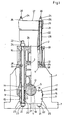
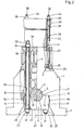
- a reciprocating piston internal combustion engine is shown partly in section and only with those parts which are necessary for understanding the invention.
- the invention is to be seen in connection with a reciprocating piston internal combustion engine, the cylinders of which have a bore diameter of approximately 400 mm and more, and the pistons of which are articulated on a crankshaft via connecting rods.
- 1 denotes a machine frame and 2 the upper chord.
- the machine frame 1 has an intermediate floor 3, approximately at the level of its bending-neutral zone, the underside of which is designated by 4.
- the machine frame 1 is in one piece and cast from simple gray cast iron, for example of the designation GG 25 or GG 20.
- the crankshaft 5 is suspended on the machine frame 1 via bearing caps 6 which are attached from below.
- the latter has indentations with lateral contact surfaces 8, 9, 10 and 11 above its base plate tightened with 7 in the crank chamber, and upper contact surfaces 13, 14 aligned with one another on both sides of an upper crankshaft bearing half 12.
- the bearing caps 6 rest with their side surfaces 15, 16 and with their top side 17 perpendicular to the side surfaces 15, 16 in such a way that that the lower crankshaft bearing halves 18 located in the bearing caps 6 complement each other with the associated upper crankshaft bearing half 11.
- the bearing caps 6 for fastening them to the machine frame 1, like this one, do not have a thread, but instead have through holes 19 and 20 which are aligned with one another for the passage of tie rods 21.
- the latter completely penetrate the through bores 19 and 20 and carry a nut 24, 25 at each end on threaded pins 22, 23; the upper nut 24 seated on the threaded pin 22 is supported on a contact surface 26 on the upper side of the upper flange 2 on the machine frame 1, while the lower nut on the threaded pin 23 is supported on a contact surface 27 on the underside of the bearing cover.
- the cylinder liners designated by 28 are fixed by cylinder heads 29 placed above, also via tie rods 30 on the machine frame, the tie rods 30 also penetrating through bores 31 in the cylinder heads 29, 32 in the upper parts of the cylinder sleeves 28 and 33 in the machine frame 1 and at their upper and lower ends each have a threaded pin 34 or 36, of which at least the upper (34) nuts 36 carry. The latter are supported on contact surfaces 37 on the top of the cylinder heads 29.
- the tie rods 30 are axially fixed according to the invention to the intermediate floor 3 of the machine frame 1.
- each tie rod 30 penetrates the associated through hole 33, which also penetrates the intermediate floor 3, and carries a nut 38 on its lower threaded pin 35, which is located on the underside 4 of the
- each tie rod 30 also penetrates the associated through hole 33 in the machine frame 1, but the through hole 33 is here provided in the region of the intermediate floor 3 with a thread in which the tie rod 30 with its threaded pin 35 located at the lower end is set.
- each tie rod 21 or 30 is extended at least with its threaded pin 22 or 34 located at the upper end beyond the nut 24 or 36 and forms with this protruding part a support base for attaching and holding a tie rod tension-- or nut release device.
- the latter is a hydraulically operated special tool that is usually delivered to a customer together with the machine.
Landscapes
- Engineering & Computer Science (AREA)
- General Engineering & Computer Science (AREA)
- Mechanical Engineering (AREA)
- Chemical & Material Sciences (AREA)
- Combustion & Propulsion (AREA)
- Cylinder Crankcases Of Internal Combustion Engines (AREA)
Applications Claiming Priority (2)
| Application Number | Priority Date | Filing Date | Title |
|---|---|---|---|
| DE3242498A DE3242498C2 (de) | 1982-11-18 | 1982-11-18 | Hubkolbenbrennkraftmaschine |
| DE3242498 | 1982-11-18 |
Publications (3)
| Publication Number | Publication Date |
|---|---|
| EP0109596A2 true EP0109596A2 (fr) | 1984-05-30 |
| EP0109596A3 EP0109596A3 (en) | 1986-01-02 |
| EP0109596B1 EP0109596B1 (fr) | 1987-08-12 |
Family
ID=6178345
Family Applications (1)
| Application Number | Title | Priority Date | Filing Date |
|---|---|---|---|
| EP83111059A Expired EP0109596B1 (fr) | 1982-11-18 | 1983-11-05 | Moteur à combustion interne à piston alternatif |
Country Status (4)
| Country | Link |
|---|---|
| EP (1) | EP0109596B1 (fr) |
| JP (1) | JPS59103946A (fr) |
| DE (2) | DE3242498C2 (fr) |
| ES (1) | ES527214A0 (fr) |
Cited By (2)
| Publication number | Priority date | Publication date | Assignee | Title |
|---|---|---|---|---|
| WO2005008053A1 (fr) * | 2003-07-16 | 2005-01-27 | Man B & W Diesel A/S | Moteur, notamment moteur diesel deux temps, important |
| WO2007131744A3 (fr) * | 2006-05-17 | 2008-03-13 | Man Diesel As | Dispositif pour connecter deux pièces de machine et procédé de fabrication d'un tel dispositif |
Families Citing this family (1)
| Publication number | Priority date | Publication date | Assignee | Title |
|---|---|---|---|---|
| JP2001123880A (ja) * | 1999-10-26 | 2001-05-08 | Honda Motor Co Ltd | エンジンブロック |
Family Cites Families (11)
| Publication number | Priority date | Publication date | Assignee | Title |
|---|---|---|---|---|
| DE470388C (de) * | 1929-01-15 | Charles Schaer | Maschinengestell fuer doppeltwirkende stehende Brennkraftmaschinen | |
| DE496716C (de) * | 1930-04-24 | Maschf Augsburg Nuernberg Ag | Kastengestell fuer stehende Mehrzylinderbrennkraftmaschinen | |
| DE418818C (de) * | 1924-10-14 | 1925-09-22 | Maschf Augsburg Nuernberg Ag | Kastengestell fuer Verbrennungskraftmaschinen mit das Gestell durchsetzenden Zugankern |
| FR861250A (fr) * | 1938-12-17 | 1941-02-04 | Perfectionnements apportés aux cylindres des moteurs à combustion interne | |
| FR895692A (fr) * | 1942-07-13 | 1945-01-31 | Perfectionnements aux moteurs à combustion interne à deux temps | |
| FR1246475A (fr) * | 1960-01-15 | 1960-11-18 | Schwermaschb Karl Liebknecht | Carter de vilebrequin pour moteurs à combustion interne |
| US3046952A (en) * | 1960-02-11 | 1962-07-31 | Dolza John | Internal combustion engines |
| DE1961804C3 (de) * | 1969-12-10 | 1973-01-11 | Kloeckner Humboldt Deutz Ag | Zylinderkopfbefestigung fuer Hubkolbenbrennkraftmaschinen |
| DE2239655A1 (de) * | 1972-08-12 | 1974-02-28 | Maschf Augsburg Nuernberg Ag | Hubkolbenbrennkraftmaschine |
| JPS5216776B2 (fr) * | 1973-09-20 | 1977-05-11 | ||
| JPS5471008U (fr) * | 1977-10-28 | 1979-05-21 |
-
1982
- 1982-11-18 DE DE3242498A patent/DE3242498C2/de not_active Expired
-
1983
- 1983-11-05 DE DE8383111059T patent/DE3373006D1/de not_active Expired
- 1983-11-05 EP EP83111059A patent/EP0109596B1/fr not_active Expired
- 1983-11-11 ES ES527214A patent/ES527214A0/es active Granted
- 1983-11-17 JP JP58215127A patent/JPS59103946A/ja active Granted
Cited By (3)
| Publication number | Priority date | Publication date | Assignee | Title |
|---|---|---|---|---|
| WO2005008053A1 (fr) * | 2003-07-16 | 2005-01-27 | Man B & W Diesel A/S | Moteur, notamment moteur diesel deux temps, important |
| WO2007131744A3 (fr) * | 2006-05-17 | 2008-03-13 | Man Diesel As | Dispositif pour connecter deux pièces de machine et procédé de fabrication d'un tel dispositif |
| CN101449047B (zh) * | 2006-05-17 | 2011-12-21 | 曼柴油机涡轮机欧洲股份公司曼柴油机涡轮机德国分公司 | 用于连接两个机械部件的装置和这样的装置的制造方法 |
Also Published As
| Publication number | Publication date |
|---|---|
| DE3242498C2 (de) | 1985-07-11 |
| DE3373006D1 (en) | 1987-09-17 |
| JPH0433979B2 (fr) | 1992-06-04 |
| ES8406637A1 (es) | 1984-08-01 |
| ES527214A0 (es) | 1984-08-01 |
| EP0109596B1 (fr) | 1987-08-12 |
| EP0109596A3 (en) | 1986-01-02 |
| JPS59103946A (ja) | 1984-06-15 |
| DE3242498A1 (de) | 1984-05-24 |
Similar Documents
| Publication | Publication Date | Title |
|---|---|---|
| DE19604547B4 (de) | Gehäuse für eine Hubkolbenbrennkraftmaschine | |
| DE60005884T2 (de) | Verbindungsstruktur eines Flugzeugfahrwerkes zum Flugzeugrumpf | |
| DE3524558C2 (fr) | ||
| EP1385664B1 (fr) | Procede et dispositif d'usinage de pieces annulaires | |
| DE69317215T2 (de) | Pleuelstange aus zwei Teilen, die aufeinander befestigt sind | |
| EP0003139A1 (fr) | Procédé, produit brut et dispositif pour le forgeage d'un arbre de manivelle | |
| EP0931213A1 (fr) | Piston compose | |
| EP0978336A1 (fr) | Paroi de lingotière d'une installation de coulée continue | |
| EP0109596B1 (fr) | Moteur à combustion interne à piston alternatif | |
| DE102007037461A1 (de) | Brennkraftmaschine mit einem Zylinderkurbelgehäuse und einem Zylindergehäuseunterteil | |
| DE2020507A1 (de) | Hydraulikzylindereinrichtung an einer hydraulischen Presse | |
| DE4026827C2 (de) | Befestigungsvorrichtung zur lösbaren Verbindung von Werkzeug und Werkzeugträger einer Stauchpresse | |
| DE3120775C2 (de) | Flanschkonstruktion für die Schraubverbindung zwischen einem Anhänger-Fahrgestell und dem Rahmen des Anhänger-Aufbaues | |
| EP3452712B1 (fr) | Piston | |
| DE29508953U1 (de) | Schraubenspannvorrichtung für die Deckelverschraubung an Reaktordruckbehältern u.dgl. | |
| DE3319864C1 (de) | Mehrteiliger Tauchkolben für Verbrennungsmotoren | |
| AT390309B (de) | Gebaute kurbelwelle | |
| DE3310894C1 (de) | Schere fuer Material beliebiger Art | |
| DE19850759B4 (de) | Radbefestigung | |
| AT517578B1 (de) | Kolben einer brennkraftmaschine | |
| DE4420265A1 (de) | Verfahren zur Herstellung eines Pleuels aus Blech | |
| DE29710312U1 (de) | Nivellierelement | |
| DE2234224A1 (de) | Vorrichtung zum versteifen eines pressengestelles, insbesondere einer einstaender-exzenterpresse | |
| DE1034920B (de) | Stahlgestell in Leichtgewichtsbauart fuer stehende Brennkraftmaschinen | |
| DE10260197A1 (de) | Maschinengehäuse für eine Brennkraftmaschine |
Legal Events
| Date | Code | Title | Description |
|---|---|---|---|
| PUAI | Public reference made under article 153(3) epc to a published international application that has entered the european phase |
Free format text: ORIGINAL CODE: 0009012 |
|
| AK | Designated contracting states |
Designated state(s): CH DE FR GB LI NL |
|
| PUAL | Search report despatched |
Free format text: ORIGINAL CODE: 0009013 |
|
| AK | Designated contracting states |
Designated state(s): CH DE FR GB LI NL |
|
| 17P | Request for examination filed |
Effective date: 19851115 |
|
| RAP1 | Party data changed (applicant data changed or rights of an application transferred) |
Owner name: M.A.N. - B&W DIESEL GMBH |
|
| 17Q | First examination report despatched |
Effective date: 19860902 |
|
| GRAA | (expected) grant |
Free format text: ORIGINAL CODE: 0009210 |
|
| AK | Designated contracting states |
Kind code of ref document: B1 Designated state(s): CH DE FR GB LI NL |
|
| REF | Corresponds to: |
Ref document number: 3373006 Country of ref document: DE Date of ref document: 19870917 |
|
| ET | Fr: translation filed | ||
| PLBE | No opposition filed within time limit |
Free format text: ORIGINAL CODE: 0009261 |
|
| STAA | Information on the status of an ep patent application or granted ep patent |
Free format text: STATUS: NO OPPOSITION FILED WITHIN TIME LIMIT |
|
| 26N | No opposition filed | ||
| REG | Reference to a national code |
Ref country code: GB Ref legal event code: IF02 |
|
| PGFP | Annual fee paid to national office [announced via postgrant information from national office to epo] |
Ref country code: CH Payment date: 20021017 Year of fee payment: 20 |
|
| PGFP | Annual fee paid to national office [announced via postgrant information from national office to epo] |
Ref country code: GB Payment date: 20021030 Year of fee payment: 20 |
|
| PGFP | Annual fee paid to national office [announced via postgrant information from national office to epo] |
Ref country code: FR Payment date: 20021104 Year of fee payment: 20 |
|
| PGFP | Annual fee paid to national office [announced via postgrant information from national office to epo] |
Ref country code: DE Payment date: 20021111 Year of fee payment: 20 |
|
| PGFP | Annual fee paid to national office [announced via postgrant information from national office to epo] |
Ref country code: NL Payment date: 20021114 Year of fee payment: 20 |
|
| PG25 | Lapsed in a contracting state [announced via postgrant information from national office to epo] |
Ref country code: LI Free format text: LAPSE BECAUSE OF EXPIRATION OF PROTECTION Effective date: 20031104 Ref country code: GB Free format text: LAPSE BECAUSE OF EXPIRATION OF PROTECTION Effective date: 20031104 Ref country code: CH Free format text: LAPSE BECAUSE OF EXPIRATION OF PROTECTION Effective date: 20031104 |
|
| PG25 | Lapsed in a contracting state [announced via postgrant information from national office to epo] |
Ref country code: NL Free format text: LAPSE BECAUSE OF EXPIRATION OF PROTECTION Effective date: 20031105 |
|
| REG | Reference to a national code |
Ref country code: GB Ref legal event code: PE20 |
|
| REG | Reference to a national code |
Ref country code: CH Ref legal event code: PL |
|
| NLV7 | Nl: ceased due to reaching the maximum lifetime of a patent |
Effective date: 20031105 |