EP0109596A2 - Reciprocating pistons internal combustion engine - Google Patents
Reciprocating pistons internal combustion engine Download PDFInfo
- Publication number
- EP0109596A2 EP0109596A2 EP83111059A EP83111059A EP0109596A2 EP 0109596 A2 EP0109596 A2 EP 0109596A2 EP 83111059 A EP83111059 A EP 83111059A EP 83111059 A EP83111059 A EP 83111059A EP 0109596 A2 EP0109596 A2 EP 0109596A2
- Authority
- EP
- European Patent Office
- Prior art keywords
- machine frame
- tie rods
- holes
- internal combustion
- cylinder
- Prior art date
- Legal status (The legal status is an assumption and is not a legal conclusion. Google has not performed a legal analysis and makes no representation as to the accuracy of the status listed.)
- Granted
Links
Images
Classifications
-
- F—MECHANICAL ENGINEERING; LIGHTING; HEATING; WEAPONS; BLASTING
- F02—COMBUSTION ENGINES; HOT-GAS OR COMBUSTION-PRODUCT ENGINE PLANTS
- F02F—CYLINDERS, PISTONS OR CASINGS, FOR COMBUSTION ENGINES; ARRANGEMENTS OF SEALINGS IN COMBUSTION ENGINES
- F02F7/00—Casings, e.g. crankcases or frames
-
- F—MECHANICAL ENGINEERING; LIGHTING; HEATING; WEAPONS; BLASTING
- F16—ENGINEERING ELEMENTS AND UNITS; GENERAL MEASURES FOR PRODUCING AND MAINTAINING EFFECTIVE FUNCTIONING OF MACHINES OR INSTALLATIONS; THERMAL INSULATION IN GENERAL
- F16C—SHAFTS; FLEXIBLE SHAFTS; ELEMENTS OR CRANKSHAFT MECHANISMS; ROTARY BODIES OTHER THAN GEARING ELEMENTS; BEARINGS
- F16C9/00—Bearings for crankshafts or connecting-rods; Attachment of connecting-rods
- F16C9/02—Crankshaft bearings
- F16C9/03—Arrangements for adjusting play
-
- F—MECHANICAL ENGINEERING; LIGHTING; HEATING; WEAPONS; BLASTING
- F02—COMBUSTION ENGINES; HOT-GAS OR COMBUSTION-PRODUCT ENGINE PLANTS
- F02F—CYLINDERS, PISTONS OR CASINGS, FOR COMBUSTION ENGINES; ARRANGEMENTS OF SEALINGS IN COMBUSTION ENGINES
- F02F1/00—Cylinders; Cylinder heads
- F02F1/02—Cylinders; Cylinder heads having cooling means
- F02F1/10—Cylinders; Cylinder heads having cooling means for liquid cooling
- F02F1/102—Attachment of cylinders to crankcase
-
- F—MECHANICAL ENGINEERING; LIGHTING; HEATING; WEAPONS; BLASTING
- F02—COMBUSTION ENGINES; HOT-GAS OR COMBUSTION-PRODUCT ENGINE PLANTS
- F02F—CYLINDERS, PISTONS OR CASINGS, FOR COMBUSTION ENGINES; ARRANGEMENTS OF SEALINGS IN COMBUSTION ENGINES
- F02F7/00—Casings, e.g. crankcases or frames
- F02F7/006—Camshaft or pushrod housings
- F02F2007/0063—Head bolts; Arrangements of cylinder head bolts
Definitions
- the invention relates to a reciprocating piston internal combustion engine, the cylinders of which have a bore diameter of approximately 400 mm and more.
- the main advantage over a conventional multi-part machine frame held together by tie rods is the one-piece structure of the machine frame due to the elimination of known disadvantageous joints.
- the machine frame may accordingly over a conventional zugankerlosen cast machine frame lighter and correspondingly simpler casting material can be used.
- the extension of the threaded pins at least at the upper end of the tie rods to a certain extent beyond the nuts enables the attachment of a tie rod tensioning or nut release device. This is a considerable advantage, particularly in the case of internal combustion engines of the generic size, because there is no need to handle heavy tools in the drive room.
- the construction principle of the through bores of the machine frame and the tie rods penetrating the bearing cover enables a relatively simple assembly of the crankshaft.
- a reciprocating piston internal combustion engine is shown partly in section and only with those parts which are necessary for understanding the invention.
- the invention is to be seen in connection with a reciprocating piston internal combustion engine, the cylinders of which have a bore diameter of approximately 400 mm and more, and the pistons of which are articulated on a crankshaft via connecting rods.
- 1 denotes a machine frame and 2 the upper chord.
- the machine frame 1 has an intermediate floor 3, approximately at the level of its bending-neutral zone, the underside of which is designated by 4.
- the machine frame 1 is in one piece and cast from simple gray cast iron, for example of the designation GG 25 or GG 20.
- the crankshaft 5 is suspended on the machine frame 1 via bearing caps 6 which are attached from below.
- the latter has indentations with lateral contact surfaces 8, 9, 10 and 11 above its base plate tightened with 7 in the crank chamber, and upper contact surfaces 13, 14 aligned with one another on both sides of an upper crankshaft bearing half 12.
- the bearing caps 6 rest with their side surfaces 15, 16 and with their top side 17 perpendicular to the side surfaces 15, 16 in such a way that that the lower crankshaft bearing halves 18 located in the bearing caps 6 complement each other with the associated upper crankshaft bearing half 11.
- the bearing caps 6 for fastening them to the machine frame 1, like this one, do not have a thread, but instead have through holes 19 and 20 which are aligned with one another for the passage of tie rods 21.
- the latter completely penetrate the through bores 19 and 20 and carry a nut 24, 25 at each end on threaded pins 22, 23; the upper nut 24 seated on the threaded pin 22 is supported on a contact surface 26 on the upper side of the upper flange 2 on the machine frame 1, while the lower nut on the threaded pin 23 is supported on a contact surface 27 on the underside of the bearing cover.
- the cylinder liners designated by 28 are fixed by cylinder heads 29 placed above, also via tie rods 30 on the machine frame, the tie rods 30 also penetrating through bores 31 in the cylinder heads 29, 32 in the upper parts of the cylinder sleeves 28 and 33 in the machine frame 1 and at their upper and lower ends each have a threaded pin 34 or 36, of which at least the upper (34) nuts 36 carry. The latter are supported on contact surfaces 37 on the top of the cylinder heads 29.
- the tie rods 30 are axially fixed according to the invention to the intermediate floor 3 of the machine frame 1.
- each tie rod 30 penetrates the associated through hole 33, which also penetrates the intermediate floor 3, and carries a nut 38 on its lower threaded pin 35, which is located on the underside 4 of the
- each tie rod 30 also penetrates the associated through hole 33 in the machine frame 1, but the through hole 33 is here provided in the region of the intermediate floor 3 with a thread in which the tie rod 30 with its threaded pin 35 located at the lower end is set.
- each tie rod 21 or 30 is extended at least with its threaded pin 22 or 34 located at the upper end beyond the nut 24 or 36 and forms with this protruding part a support base for attaching and holding a tie rod tension-- or nut release device.
- the latter is a hydraulically operated special tool that is usually delivered to a customer together with the machine.
Abstract
Description
Die Erfindung betrifft eine Hubkolbenbrennkraftmaschine, deren Zylinder einen Bohrungsdurchmesser von etwa 400 mm und mehr besitzen.The invention relates to a reciprocating piston internal combustion engine, the cylinders of which have a bore diameter of approximately 400 mm and more.
Hubkolbenbrennkraftmaschinen dieser Größenordnung besitzen in der Regel ein mehrteiliges Maschinengestell, dessen einzelne Teile durch Schrauben bzw. Zuganker miteinander verbunden sind. Die Kurbelwelle ist hängend über von unten her angesetzte Lagerdeckel oder stehend über von oben her angesetzte Lagerdeckel am Maschinengestell gelagert. Als Grundlagerschrauben sind dabei Stiftschrauben verwendet, die in Sacklochgewindebohrungen im Lagerstuhl eingeschraubt sind. Die Zylinderkopfschrauben sind ebenfalls als Stiftschrauben ausgebildet und in den Obergurt des Maschinengestelles in entsprechende Sacklochgewindelöcher eingeschraubt. Für diese Art der Befestigung der Lagerdeckel und Zylinderköpfe müssen maschinengestellseitig gewisse Vorkehrungen getroffen sein. Da durch die besagte Schraubverbindung die einzelnen Maschinengestellteile nicht nur auf Druck, sondern auch beim Arbeitstakt auf Zug beansprucht werden, ist für das Maschinengestell in jedem Fall ein hochwertiges Gußmaterial erforderlich. Einfacher Grauguß würde den erforderlichen Belastungen nicht standhalten. Außerdem sind Gußanhäufungen im Bereich der Sacklochgewindebohrungen unumgänglich, was üblicherweise zu relativ schwierig zu gießenden Formen führt.Reciprocating piston internal combustion engines of this size generally have a multi-part machine frame, the individual parts of which are connected to one another by screws or tie rods. The crankshaft is suspended from the machine frame via bearing caps attached from below or standing vertically via bearing caps attached from above. Stud bolts are used as base screws, which are screwed into blind holes in the bearing bracket. The cylinder head screws are also designed as stud bolts and screwed into the top chord of the machine frame in corresponding blind hole holes. Certain precautions must be taken on the machine frame side for this type of attachment of the bearing caps and cylinder heads. Since the screw connection means that the individual machine frame parts are not only subjected to pressure, but also to train during the work cycle, a high-quality casting material is required for the machine frame in any case. Simple gray cast iron would not withstand the necessary loads. In addition, accumulations of castings are inevitable in the area of the blind hole, which usually leads to molds which are relatively difficult to cast.
Es ist daher Aufgabe der Erfindung, für Hubkolbenbrennkraftmaschinen der eingangs definierten Größenordnung ein Bauprinzip vorzuschlagen, durch das gegenüber nach bislang bekannten Bauprinzipien hergestellten Brennkraftmaschinen eine wesentlich kostengünstigere, wirtschaftlichere Herstellung, insbesondere des Maschinengestelles möglich ist, außerdem das Ausschußrisiko bei der Maschinengestellfertigung stark verminderbar, weniger Material erforderlich und damit Gewicht einzusparen ist und über dies sowohl für Erstmontage von Kurbelwelle, Zylinderbuchsen und Zylinderköpfen als auch für Wartungsarbeiten günstige Verhältnisse gewährleistet sind.It is therefore an object of the invention to propose a construction principle for reciprocating piston internal combustion engines of the size defined at the outset, by means of which a considerably more cost-effective, more economical production, in particular of the machine frame, is possible compared to internal combustion engines manufactured according to previously known construction principles, and also the risk of rejects in machine frame manufacture can be greatly reduced, less material required and thus saving weight, and this ensures favorable conditions both for the initial assembly of the crankshaft, cylinder liners and cylinder heads and for maintenance work.
Diese Aufgabe ist erfindungsgemäß bei einer Hubkolbenbrennkraftmaschine der eingangs definierten Größenordnung durch die Kombination der in Anspruch 1 angegebenen Merkmale gelöst. Vorteilhafte Ausgestaltungen und Weiterbildungen dieser Lösung sind in den Unteransprüchen gekennzeichnet.This object is achieved according to the invention in a reciprocating piston internal combustion engine of the magnitude defined at the outset by the combination of the features specified in claim 1. Advantageous refinements and developments of this solution are characterized in the subclaims.
Durch den Entfall von großen Gewinden im gegossenen Maschinengestell ergeben sich gegenüber einem konventionellen, zugankerlosen Gestell geringere Gußanhäufungen. Das Gußausschußrisiko sinkt; es ergeben sich fertigungstechnische Vereinfachungen. Gegenüber einem konventionellen mehrteiligen, zugankerzusammengehaltenen Maschinengestell besteht der Hauptvorteil in der Einteiligkeit des Maschinengestells durch den Wegfall bekannt nachteiliger Trennfugen. Durch das Angreifen der zum Zylinderkopf führenden Zuganker am Zwischenboden des Maschinengestells wird am Obergurt desselben eine Reduzierung der auftretenden dynamischen Spannungen erzielt; letzteres deshalb, weil die Beanspruchungen, herrührend aus Zugankerspannkraft und Zylinderbuchsenauflagepressung, sowohl auf den Obergurt des Maschinengestells, als auch den Zwischenboden aufgeteilt werden. Da die Zündkräfte weitgehend von den die Lagerdeckel haltenden Zugankern aufgenommen werden und sich deshalb im Gußmaterial des Maschinengestells vergleichsweise geringe dynamische Spannungen ergeben, die außerdem durch die Druckvorspannung in den Bereich höherer Dauerfestigkeitswerte verlagert werden, kann das Maschinengestell gegenüber einem konventionellen zugankerlosen, gegossenen Maschinengestell entsprechend leichter ausgebildet und auch entsprechend einfacheres Gußmaterial verwendet werden. Die Verlängerung der Gewindezapfen zumindest am oberen Ende der Zuganker um ein gewisses Maß über die Muttern hinaus ermöglicht das Ansetzen einer Zugankerspann- bzw. Mutterlösevorrichtung. Dies stellt insbesondere bei Brennkraftmaschinen der gattungsgemäßen Größenordnung einen erheblichen Vorteil dar, weil das Hantieren mit schweren Werkzeugen im Triebraum entfällt. Darüber hinaus ermöglicht das Bauprinzip der Durchgangsbohrungen des Maschinengestells und der Lagerdeckel durchdringenden Zuganker eine relativ einfache Montage der Kurbelwelle.Due to the elimination of large threads in the cast machine frame, there is less accumulation of castings than a conventional frame without a tie rod. The risk of casting waste decreases; there are manufacturing simplifications. The main advantage over a conventional multi-part machine frame held together by tie rods is the one-piece structure of the machine frame due to the elimination of known disadvantageous joints. By gripping the tie rods leading to the cylinder head on the intermediate floor of the machine frame, a reduction in the dynamic stresses occurring is achieved on the upper flange thereof; the latter because the stresses resulting from the tension of the tie rod and the cylinder liner bearing pressure are distributed to both the upper flange of the machine frame and the intermediate floor. D are largely taken up by the bearing cap retaining tie rods a, the firing forces and therefore arise in the cast material of the machine frame a comparatively low dynamic voltages which are also displaced by the pressure bias in the range of higher fatigue strength, the machine frame may accordingly over a conventional zugankerlosen cast machine frame lighter and correspondingly simpler casting material can be used. The extension of the threaded pins at least at the upper end of the tie rods to a certain extent beyond the nuts enables the attachment of a tie rod tensioning or nut release device. This is a considerable advantage, particularly in the case of internal combustion engines of the generic size, because there is no need to handle heavy tools in the drive room. In addition, the construction principle of the through bores of the machine frame and the tie rods penetrating the bearing cover enables a relatively simple assembly of the crankshaft.
Nachstehend ist das erfindungsgemäße Bauprinzip für Hubkolbenbrennkraftmaschinen anhand der Zeichnung näher erläutert. In der Zeichnung zeigen:
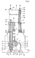
- Fig.1 ein erstes Ausführungsbeispiel einer Hubkolbenbrennkraftmaschine nach dem erfindungsgemäßen Bauprinzip,
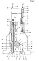
- Fig.2 ein zweites Ausführungsbeispiel einer Hubkolbenbrennkraftmaschine nach dem erfindungsgemäßen Bauprinzip.
- 1 shows a first embodiment of a reciprocating piston internal combustion engine according to the construction principle according to the invention,
- 2 shows a second embodiment of a reciprocating piston internal combustion engine according to the construction principle of the invention.
In den beiden Figuren der Zeichnung ist jeweils eine Hubkolbenbrennkraftmaschine teilweise im Schnitt und nur mit jenen Teilen dargestellt, die für das Verständnis der Erfindung erforderlich sind. Die Erfindung ist im Zusammenhang mit einer Hubkolbenbrennkraftmaschine zu sehen, deren Zylinder einen Bohrungsdurchmesser von etwa 400 mm und mehr besitzen und deren Kolben über Pleuel an einer Kurbelwelle angelenkt sind.In the two figures of the drawing, a reciprocating piston internal combustion engine is shown partly in section and only with those parts which are necessary for understanding the invention. The invention is to be seen in connection with a reciprocating piston internal combustion engine, the cylinders of which have a bore diameter of approximately 400 mm and more, and the pistons of which are articulated on a crankshaft via connecting rods.
In den Figuren sind gleiche bzw. einander entsprechende Teile.mit gleichen Bezugszeichen angezogen. Mit 1 ist dabei ein Maschinengestell und mit 2 dessen Obergurt bezeichnet. Das Maschinengestell 1 weist erfindungsgemäß etwa in Höhe seiner biegeneutralen Zone einen Zwischenboden 3 auf, dessen Unterseite mit 4 bezeichnet ist.In the figures, the same or corresponding parts are drawn with the same reference numerals. 1 denotes a machine frame and 2 the upper chord. According to the invention, the machine frame 1 has an intermediate floor 3, approximately at the level of its bending-neutral zone, the underside of which is designated by 4.
Entsprechend einem weiteren Kriterium der Erfindung ist das Maschinengestell 1 einteilig und aus einfachem Grauguß, beispielsweise solchem der Bezeichnung GG 25 oder GG 20, gegossen. Darüber hinaus ist - ebenfalls erfindungsgemäß - die Kurbelwelle 5 hängend über von unten her angesetzte Lagerdeckel 6 am Maschinengestell 1 gelagert. Hierzu weist letzteres oberhalb seiner mit 7 angezogenen Grundplatte im Kurbelraum Einbuchtungen mit seitlichen Anlageflächen 8, 9, 10 und 11 sowie beiderseits einer oberen Kurbelwellenlagerhälfte 12 zueinander fluchtende obere Anlageflächen 13, 14 auf. An diesen Anlageflächen 8, 9, 10, 11, 13 und 14 liegen die Lagerdeckel 6 mit ihren Seitenflächen 15, 16 sowie mit ihrer senkrecht zu den Seitenflächen 15, 16 stehenden Oberseite 17 derart an, daß sich die in den Lagerdeckeln 6 befindlichen unteren Kurbelwellenlagerhälften 18 mit der jeweils zugehörigen oberen Kurbelwellenlagerhälfte 11 ergänzen.According to a further criterion of the invention, the machine frame 1 is in one piece and cast from simple gray cast iron, for example of the designation GG 25 or GG 20. In addition - likewise according to the invention - the
Entsprechend einem weiteren erfindungsgemäßen Kriterium weisen die Lagerdeckel 6 zu ihrer Befestigung am Maschinengestell 1 ebenso wie dieses keine Gewinde, sondern jeweils zueinander fluchtende Durchgangsbohrungen 19 und 20 zur Hindurchführung von Zugankern 21 auf. Letztere durchdringen dabei erfindungsgemäß die Durchgangsbohrungen 19 und 20 vollständig und tragen an jedem Ende auf Gewindezapfen 22, 23 je eine Mutter 24, 25; dabei stützt sich die auf dem Gewindezapfen 22 sitzende obere Mutter 24 an einer Anlagefläche 26 an der Oberseite des Obergurtes 2 am Maschinengestell 1, die am Gewindezapfen 23 sitzende untere Mutter dagegen an einer Anlagefläche 27 an der Lagerdeckelunterseite ab.According to a further criterion according to the invention, the
Entsprechend einem weiteren Merkmal der Erfindung sind die mit 28 bezeichneten Zylinderbuchsen durch oben aufgesetzte Zylinderköpfe 29 ebenfalls über Zuganker 30 am Maschinengestell festgelegt, wobei die Zuganker 30 ebenfalls Durchgangsbohrungen 31 in den Zylinderköpfen 29, 32 in den Oberteilen der Zylinderbuchsen 28 und 33 im Maschinengestell 1 durchdringen sowie an ihren oberen und unteren Enden jeweils einen Gewindezapfen 34 bzw. 36 aufweisen, von denen zumindest die oberen (34) Muttern 36 tragen. Letztere stützen sich an Anlageflächen 37 an der Oberseite der Zylinderköpfe 29 ab. An ihren unteren Enden sind die Zuganker 30 erfindungsgemäß am Zwischenboden 3 des Maschinengestells 1 axial festgelegt. Beim Ausführungsbeispiel gemäß Fig.1 durchdringt dabei jeder Zuganker 30 die zugehörige, auch den Zwischenboden 3 durchsetzende Durchgangsbohrung 33 und trägt auf seinem unteren Gewindezapfen 35 eine Mutter 38, die sich an der Unterseite 4 desAccording to a further feature of the invention, the cylinder liners designated by 28 are fixed by
Zwischenbodens 3 abstützt. Beim Ausführungsbeispiel gemäß Fig.2 dagegen durchdringt jeder Zuganker 30 zwar auch die zugehörige Durchgangsbohrung 33 im Maschinengestell 1, jedoch ist die Durchgangsbohrung 33 hier im Bereich des Zwischenbodens 3 mit einem Gewinde versehen, in dem der Zuganker 30 mit seinem am unteren Ende sitzenden Gewindezapfen 35 festgelegt ist.Intermediate floor 3 supports. In the exemplary embodiment according to FIG. 2, on the other hand, each
Entsprechend einem weiteren Kriterium der Erfindung ist jeder Zuganker 21 bzw. 30 zumindest mit seinem am oberen Ende sitzenden Gewindezapfen 22 bzw. 34 über die Mutter 24 bzw. 36 hinaus verlängert und bildet mit diesem überstehenden Teil einen Tragsockel zum Ansetzen und Halten einer Zugankerspann--bzw.Mutterlösevorrichtung. Bei letzterer handelt es sich um ein hydraulisch betätigbares Spezialwerkzeug, das in der Regel zusammen mit der Maschine an einen Kunden ausgeliefert wird.According to a further criterion of the invention, each
- 1 Maschinengestell1 machine frame
- 2 Obergurt an 12 top chord on 1
- 3 Zwischenboden3 mezzanine
- 4 Unterseite von 34 bottom of 3
- 5 Kurbelwelle5 crankshaft
- 6 Lagerdeckel6 bearing caps
- 7 Grundplatte von 17 base plate of 1
- 8 Anlagefläche seitlich an 18 contact surface on the side on 1
- 9 "9 "
- 10 "10 "
- 11 "11 "
- 12 obere Kurbelwellenlagerhälfte12 upper crankshaft bearing half
- 13 obere Anlagefläche an 113 upper contact surface on 1
- 14 "14 "
- 15 Seitenfläche an 615 sides on 6
- 16 "16 "
- 17 Oberseite von 617 top of 6
- 18 untere Kurbelwellenlagerhälfte18 lower crankshaft bearing half
- 19 Durchgangsbohrung in 119 through hole in 1
- 20 " 620 "6
- 21 Zuganker21 tie rods
- 22 Gewindezapfen22 threaded pins
- 23 "23 "
- 24 Mutter auf 2224 mother on 22
- 25 Mutter auf 2325 mother to 23
- 26 Anlagefläche an 1 für 2426 contact surface at 1 for 24
- 27 Anlagefläche an 6 für 2527 contact surface at 6 for 25
- 28 Zylinderbuchsen28 cylinder liners
- 29 Zylinderköpfe29 cylinder heads
- 30 Zuganker30 tie rods
- 31 Durchgangsbohrung in 29 für 3031 through hole in 29 for 30
- 32 Durchgangsbohrung in 28 für 3032 through hole in 28 for 30
- 33 Durchgangsbohrung in 1 für 3033 through hole in 1 for 30
- 34 Gewindezapfen oben an 3034 threaded spigot on top of 30
- 35 Gewindezapfen unten an 3035 threaded pins at the bottom of 30
- 36 Muttern36 nuts
- 37 Anlagefläche an Oberseite von 2937 contact surface on top of 29
Claims (4)
Applications Claiming Priority (2)
| Application Number | Priority Date | Filing Date | Title |
|---|---|---|---|
| DE3242498A DE3242498C2 (en) | 1982-11-18 | 1982-11-18 | Reciprocating internal combustion engine |
| DE3242498 | 1982-11-18 |
Publications (3)
| Publication Number | Publication Date |
|---|---|
| EP0109596A2 true EP0109596A2 (en) | 1984-05-30 |
| EP0109596A3 EP0109596A3 (en) | 1986-01-02 |
| EP0109596B1 EP0109596B1 (en) | 1987-08-12 |
Family
ID=6178345
Family Applications (1)
| Application Number | Title | Priority Date | Filing Date |
|---|---|---|---|
| EP83111059A Expired EP0109596B1 (en) | 1982-11-18 | 1983-11-05 | Reciprocating pistons internal combustion engine |
Country Status (4)
| Country | Link |
|---|---|
| EP (1) | EP0109596B1 (en) |
| JP (1) | JPS59103946A (en) |
| DE (2) | DE3242498C2 (en) |
| ES (1) | ES8406637A1 (en) |
Cited By (2)
| Publication number | Priority date | Publication date | Assignee | Title |
|---|---|---|---|---|
| WO2005008053A1 (en) * | 2003-07-16 | 2005-01-27 | Man B & W Diesel A/S | Engine, in particular a large two-stroke diesel engine |
| WO2007131744A2 (en) * | 2006-05-17 | 2007-11-22 | Man Diesel Filial Af Man Diesel Se, Tyskland | Device for connecting two machine parts and method for producing such a device |
Families Citing this family (1)
| Publication number | Priority date | Publication date | Assignee | Title |
|---|---|---|---|---|
| JP2001123880A (en) * | 1999-10-26 | 2001-05-08 | Honda Motor Co Ltd | Engine block |
Citations (6)
| Publication number | Priority date | Publication date | Assignee | Title |
|---|---|---|---|---|
| DE470388C (en) * | 1929-01-15 | Charles Schaer | Machine frame for double-acting stationary internal combustion engines | |
| FR861250A (en) * | 1938-12-17 | 1941-02-04 | Improvements made to internal combustion engine cylinders | |
| FR895692A (en) * | 1942-07-13 | 1945-01-31 | Improvements to two-stroke internal combustion engines | |
| FR1246475A (en) * | 1960-01-15 | 1960-11-18 | Schwermaschb Karl Liebknecht | Crankshaft housing for internal combustion engines |
| US3046952A (en) * | 1960-02-11 | 1962-07-31 | Dolza John | Internal combustion engines |
| DE1961804A1 (en) * | 1969-12-10 | 1971-06-24 | Kloeckner Humboldt Deutz Ag | Cylinder head mounting for reciprocating internal combustion engines |
Family Cites Families (5)
| Publication number | Priority date | Publication date | Assignee | Title |
|---|---|---|---|---|
| DE496716C (en) * | 1930-04-24 | Maschf Augsburg Nuernberg Ag | Box frame for standing multi-cylinder internal combustion engines | |
| DE418818C (en) * | 1924-10-14 | 1925-09-22 | Maschf Augsburg Nuernberg Ag | Box frame for internal combustion engines with tie rods penetrating the frame |
| DE2239655A1 (en) * | 1972-08-12 | 1974-02-28 | Maschf Augsburg Nuernberg Ag | PISTON ENGINE |
| JPS5216776B2 (en) * | 1973-09-20 | 1977-05-11 | ||
| JPS5471008U (en) * | 1977-10-28 | 1979-05-21 |
-
1982
- 1982-11-18 DE DE3242498A patent/DE3242498C2/en not_active Expired
-
1983
- 1983-11-05 DE DE8383111059T patent/DE3373006D1/en not_active Expired
- 1983-11-05 EP EP83111059A patent/EP0109596B1/en not_active Expired
- 1983-11-11 ES ES527214A patent/ES8406637A1/en not_active Expired
- 1983-11-17 JP JP58215127A patent/JPS59103946A/en active Granted
Patent Citations (6)
| Publication number | Priority date | Publication date | Assignee | Title |
|---|---|---|---|---|
| DE470388C (en) * | 1929-01-15 | Charles Schaer | Machine frame for double-acting stationary internal combustion engines | |
| FR861250A (en) * | 1938-12-17 | 1941-02-04 | Improvements made to internal combustion engine cylinders | |
| FR895692A (en) * | 1942-07-13 | 1945-01-31 | Improvements to two-stroke internal combustion engines | |
| FR1246475A (en) * | 1960-01-15 | 1960-11-18 | Schwermaschb Karl Liebknecht | Crankshaft housing for internal combustion engines |
| US3046952A (en) * | 1960-02-11 | 1962-07-31 | Dolza John | Internal combustion engines |
| DE1961804A1 (en) * | 1969-12-10 | 1971-06-24 | Kloeckner Humboldt Deutz Ag | Cylinder head mounting for reciprocating internal combustion engines |
Non-Patent Citations (1)
| Title |
|---|
| Prospekt Fa. Ruston Paxmann (Publication No. 231) Nov. 1970 * |
Cited By (4)
| Publication number | Priority date | Publication date | Assignee | Title |
|---|---|---|---|---|
| WO2005008053A1 (en) * | 2003-07-16 | 2005-01-27 | Man B & W Diesel A/S | Engine, in particular a large two-stroke diesel engine |
| WO2007131744A2 (en) * | 2006-05-17 | 2007-11-22 | Man Diesel Filial Af Man Diesel Se, Tyskland | Device for connecting two machine parts and method for producing such a device |
| WO2007131744A3 (en) * | 2006-05-17 | 2008-03-13 | Man Diesel As | Device for connecting two machine parts and method for producing such a device |
| CN101449047B (en) * | 2006-05-17 | 2011-12-21 | 曼柴油机涡轮机欧洲股份公司曼柴油机涡轮机德国分公司 | Device for connecting two machine parts and method for producing such a device |
Also Published As
| Publication number | Publication date |
|---|---|
| EP0109596B1 (en) | 1987-08-12 |
| DE3242498C2 (en) | 1985-07-11 |
| DE3242498A1 (en) | 1984-05-24 |
| JPH0433979B2 (en) | 1992-06-04 |
| ES527214A0 (en) | 1984-08-01 |
| ES8406637A1 (en) | 1984-08-01 |
| JPS59103946A (en) | 1984-06-15 |
| DE3373006D1 (en) | 1987-09-17 |
| EP0109596A3 (en) | 1986-01-02 |
Similar Documents
| Publication | Publication Date | Title |
|---|---|---|
| DE3426208C1 (en) | Crankshaft bearings for internal combustion engines | |
| DE19604547B4 (en) | Housing for a reciprocating internal combustion engine | |
| DE102006043763A1 (en) | Replaceable wear pads, as well as methods for producing wear pads for a track | |
| DE60005884T2 (en) | Connection structure of an aircraft landing gear to the fuselage | |
| DE3524558C2 (en) | ||
| WO1998016731A1 (en) | Built-up piston | |
| EP0978336A1 (en) | Mould wall of a continuous casting plant | |
| EP0109596B1 (en) | Reciprocating pistons internal combustion engine | |
| DE102007037461A1 (en) | Internal combustion engine e.g. skirt engine, has cylinder housing lower part comprising separate bearing cap of crankshaft bearing, which is connected with cylinder crankcase by angular screw connection | |
| DE4026827C2 (en) | Fastening device for the detachable connection of tool and tool carrier of an upsetting press | |
| EP1043116A2 (en) | Clamping device for components | |
| DE102013114318B4 (en) | Multi-part crankcase and assembly process | |
| DE4403442C1 (en) | Fastening for detachable connection between foundation and machine bed | |
| DE4138441C2 (en) | Pressing tool for an upsetting press to reduce the slab width in hot wide strip roughing lines | |
| DE102022202579B4 (en) | Multi-part brake caliper for vehicle disc brakes | |
| DE2701140C3 (en) | Device for assembling and disassembling the crankshaft bearing cover of an internal combustion engine | |
| EP2014932B1 (en) | Device for connecting or attaching components using an extremely secure pretensioning screw connection and screw set for extremely secure pretensable connections | |
| DE19850759B4 (en) | Wheel mounting | |
| DE3319864C1 (en) | Multiple-part trunk piston for combustion engines | |
| EP1584810A2 (en) | Crankcase for combustion engine | |
| AT517578B1 (en) | PISTON OF AN INTERNAL COMBUSTION ENGINE | |
| DE3310894C1 (en) | Scissors for material of any kind | |
| DE102019218301A1 (en) | Connection system | |
| DE10360178A1 (en) | Device to be used for separation of bearing frame from cylinder head, designed as frame with bores for insertion of spindles | |
| DD223751A1 (en) | MAKING WORK MACHINES AND EQUIPMENT |
Legal Events
| Date | Code | Title | Description |
|---|---|---|---|
| PUAI | Public reference made under article 153(3) epc to a published international application that has entered the european phase |
Free format text: ORIGINAL CODE: 0009012 |
|
| AK | Designated contracting states |
Designated state(s): CH DE FR GB LI NL |
|
| PUAL | Search report despatched |
Free format text: ORIGINAL CODE: 0009013 |
|
| AK | Designated contracting states |
Designated state(s): CH DE FR GB LI NL |
|
| 17P | Request for examination filed |
Effective date: 19851115 |
|
| RAP1 | Party data changed (applicant data changed or rights of an application transferred) |
Owner name: M.A.N. - B&W DIESEL GMBH |
|
| 17Q | First examination report despatched |
Effective date: 19860902 |
|
| GRAA | (expected) grant |
Free format text: ORIGINAL CODE: 0009210 |
|
| AK | Designated contracting states |
Kind code of ref document: B1 Designated state(s): CH DE FR GB LI NL |
|
| REF | Corresponds to: |
Ref document number: 3373006 Country of ref document: DE Date of ref document: 19870917 |
|
| ET | Fr: translation filed | ||
| PLBE | No opposition filed within time limit |
Free format text: ORIGINAL CODE: 0009261 |
|
| STAA | Information on the status of an ep patent application or granted ep patent |
Free format text: STATUS: NO OPPOSITION FILED WITHIN TIME LIMIT |
|
| 26N | No opposition filed | ||
| REG | Reference to a national code |
Ref country code: GB Ref legal event code: IF02 |
|
| PGFP | Annual fee paid to national office [announced via postgrant information from national office to epo] |
Ref country code: CH Payment date: 20021017 Year of fee payment: 20 |
|
| PGFP | Annual fee paid to national office [announced via postgrant information from national office to epo] |
Ref country code: GB Payment date: 20021030 Year of fee payment: 20 |
|
| PGFP | Annual fee paid to national office [announced via postgrant information from national office to epo] |
Ref country code: FR Payment date: 20021104 Year of fee payment: 20 |
|
| PGFP | Annual fee paid to national office [announced via postgrant information from national office to epo] |
Ref country code: DE Payment date: 20021111 Year of fee payment: 20 |
|
| PGFP | Annual fee paid to national office [announced via postgrant information from national office to epo] |
Ref country code: NL Payment date: 20021114 Year of fee payment: 20 |
|
| PG25 | Lapsed in a contracting state [announced via postgrant information from national office to epo] |
Ref country code: LI Free format text: LAPSE BECAUSE OF EXPIRATION OF PROTECTION Effective date: 20031104 Ref country code: GB Free format text: LAPSE BECAUSE OF EXPIRATION OF PROTECTION Effective date: 20031104 Ref country code: CH Free format text: LAPSE BECAUSE OF EXPIRATION OF PROTECTION Effective date: 20031104 |
|
| PG25 | Lapsed in a contracting state [announced via postgrant information from national office to epo] |
Ref country code: NL Free format text: LAPSE BECAUSE OF EXPIRATION OF PROTECTION Effective date: 20031105 |
|
| REG | Reference to a national code |
Ref country code: GB Ref legal event code: PE20 |
|
| REG | Reference to a national code |
Ref country code: CH Ref legal event code: PL |
|
| NLV7 | Nl: ceased due to reaching the maximum lifetime of a patent |
Effective date: 20031105 |