EP0109025A2 - Gaslaser - Google Patents
Gaslaser Download PDFInfo
- Publication number
- EP0109025A2 EP0109025A2 EP83111110A EP83111110A EP0109025A2 EP 0109025 A2 EP0109025 A2 EP 0109025A2 EP 83111110 A EP83111110 A EP 83111110A EP 83111110 A EP83111110 A EP 83111110A EP 0109025 A2 EP0109025 A2 EP 0109025A2
- Authority
- EP
- European Patent Office
- Prior art keywords
- communicating
- discharge tube
- discharge
- tube structure
- laser generator
- Prior art date
- Legal status (The legal status is an assumption and is not a legal conclusion. Google has not performed a legal analysis and makes no representation as to the accuracy of the status listed.)
- Granted
Links
Images


Classifications
-
- H—ELECTRICITY
- H01—ELECTRIC ELEMENTS
- H01S—DEVICES USING THE PROCESS OF LIGHT AMPLIFICATION BY STIMULATED EMISSION OF RADIATION [LASER] TO AMPLIFY OR GENERATE LIGHT; DEVICES USING STIMULATED EMISSION OF ELECTROMAGNETIC RADIATION IN WAVE RANGES OTHER THAN OPTICAL
- H01S3/00—Lasers, i.e. devices using stimulated emission of electromagnetic radiation in the infrared, visible or ultraviolet wave range
- H01S3/05—Construction or shape of optical resonators; Accommodation of active medium therein; Shape of active medium
- H01S3/06—Construction or shape of active medium
- H01S3/07—Construction or shape of active medium consisting of a plurality of parts, e.g. segments
- H01S3/073—Gas lasers comprising separate discharge sections in one cavity, e.g. hybrid lasers
- H01S3/076—Folded-path lasers
-
- H—ELECTRICITY
- H01—ELECTRIC ELEMENTS
- H01S—DEVICES USING THE PROCESS OF LIGHT AMPLIFICATION BY STIMULATED EMISSION OF RADIATION [LASER] TO AMPLIFY OR GENERATE LIGHT; DEVICES USING STIMULATED EMISSION OF ELECTROMAGNETIC RADIATION IN WAVE RANGES OTHER THAN OPTICAL
- H01S3/00—Lasers, i.e. devices using stimulated emission of electromagnetic radiation in the infrared, visible or ultraviolet wave range
- H01S3/02—Constructional details
- H01S3/03—Constructional details of gas laser discharge tubes
- H01S3/036—Means for obtaining or maintaining the desired gas pressure within the tube, e.g. by gettering, replenishing; Means for circulating the gas, e.g. for equalising the pressure within the tube
-
- H—ELECTRICITY
- H01—ELECTRIC ELEMENTS
- H01S—DEVICES USING THE PROCESS OF LIGHT AMPLIFICATION BY STIMULATED EMISSION OF RADIATION [LASER] TO AMPLIFY OR GENERATE LIGHT; DEVICES USING STIMULATED EMISSION OF ELECTROMAGNETIC RADIATION IN WAVE RANGES OTHER THAN OPTICAL
- H01S3/00—Lasers, i.e. devices using stimulated emission of electromagnetic radiation in the infrared, visible or ultraviolet wave range
- H01S3/02—Constructional details
- H01S3/04—Arrangements for thermal management
- H01S3/041—Arrangements for thermal management for gas lasers
Definitions
- the present invention relates to a gas laser generator having improved gas cooling ducts.
- the laser beam produced by a gas laser generator has the Gaussian distribution profile of energy flux. Namely, when the energy density of the laser beam is plotted on the vertical axis against the distance of a point from the center of the laser beam on the horizontal axis, the Gaussian distribution is characterized by an extremely high energy density at the central portion of the laser beam relative to that at points in the peripheral region ranging from an intermediate point which slightly comes off the beam center to a point on the outer bound of the beam. Higher the energy density at the central portion than that in the peripheral region, better is the converging characteristics of the laser beam. In cutting or welding steel plates using a laser beam, the better laser converging characteristics allow the narrower cut or welded portion, resulting in a precise machining and reduction of machining time.
- the gas laser generator can produce a laser beam with the better converging characteristics by using a long discharge tube with a small diameter.
- a long discharge tube is made by joining a plurality of discharge tubes each having a discharge section, and it is formed in a crank structure to avoid a too large longitudinal dimension.
- a gas laser generator disclosed in U.S. Patent No. 4,351,052 has the structure of two discharge tubes disposed in parallel with discharge sections located at the right and left portions of each tube.
- a common vessel connects the ends of both discharge tubes to form a complete discharge tube structure.
- the end sections and intermediate sections of the discharge tube structure are provided with two systems of cooling ducts, each system including a heat exchanger and a centrifugal blower.
- a mixture gas e.g., C0 2 , He and N 21 circulates through the discharge tubes and cooling ducts, and the interior of the discharge tube structure is cooled.
- This arrangement uses two centrifugal blowers in two systems, making the arrangement of the cooling ducts complex. This makes it difficult the smooth feeding of the mixture gas into the discharge tubes, resulting in a lower laser output.
- the operation of two centrifugal blowers increases the vibration, resulting possibly in a positional error of the reflectors and output mirror.
- the cooling ducts are provided at both end sections and the intermediate section of the discharge tube structure
- the inventive gas laser generator comprises end common vessels and an intermediate common vessel which are communicate with all discharge tubes at their end sections and intermediate section, first and second cooling ducts communicating with the end common vessels and an intermediate common vessel, and a centrifugal blower having a first communicating port located at the center thereof for communicating with the first cooling duct and at least two second communicating ports communicating with the second cooling ducts opposed to each other with respect to the first communicating port, whereby the second communicating ports can be disposed symmetrically with respect to the intermediate common vessel and the second cooling duct can be arranged linearly so that the mixture gas is fed to the intermediate common vessel smoothly, and thus the laser output can be increased.
- a discharge tube structure 1A has a first discharge tube 1 and a second discharge tube 2 disposed in parallel and a third discharge tube 3 disposed diagonally between one end of the first discharge tube 1 and one end of the second discharge tube 2.
- the first discharge tube 1 is provided at its another end with an output mirror 5, which irradiates a laser beam 6 outside as shown by the arrow.
- the first reflector 7 is placed askew at the joint section of the first and third discharge tubes 1 and 3
- the second reflector 8 is placed askew at the joint section of the second and third discharge tubes 2 and 3.
- the second discharge tube 2 is provided with a reflector 9 at its another end.
- the first and second reflectors 7 and 8 are placed askew at an appropriate angle with respect to the related discharge tubes, so that the second reflector 8 and the output mirror 5 substantially confront with each other via the reflector 7, and the first reflector 7 and the reflector 9 substantially confront with each other via the reflector 8.
- a pair of discharge sections 10 and 11 are each made up of a cathode 12A and an anode 12B, and are located within each discharge tube.
- End common vessels 13 and an intermediate common vessel 14 are provided at both end sections and intermediate section of the discharge tube structure respectively, so that the discharge tubes 1, 2 and 3 communicate with one another.
- In-ports 15 and 16 are formed at both ends of the intermediate common vessel 14, which is provided therein with a partition plate 17 placed askew between the in-parts 15 and 16.
- the mixture gas 18 entering through the in-ports 15 and 16 flows evenly to the discharge sections 10 and 11 in each discharge tube as shown by the arrows.
- Out-ports 19 are provided in the end common vessels between the first and second discharge tubes 1 and 2. Inside the end common vessels, heat exchangers 20 are provided.
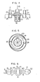
- a centrifugal blower 22 has the first communicating port 23 and second communicating ports 24 and 25 communicating with the out-ports 19 and in-ports 15 and 16 through the first cooling duct 26 and second cooling ducts 27, respectively.
- the first communicating port 23 is formed in the center of the centrifugal blower, while the communicating ports 24 and 25 are formed in both ends of a blower case 28 so that they are located symmetrically with respect to the first communicating port 23.
- the second communicating ports 24 and 25 partly communicate with the first communicating port 23, while one communicating port 24 and another communicating port 25 are separated by a partition plate 29.
- Located beneath the first communicating port 23 is a vane wheel 30 which is coupled to a drive shaft 32 of a high frequency motor 31. This arrangement of the centrifugal blower is called perpendicular placement, since the drive shaft 32 is oriented perpendicularly to the laser beam 6.
- the second cooling ducts from the second communicating ports to the intermediate common vessel can have a minimal length, allowing the mixture gas 18 from the second communicating ports 24-and 25 to flow smoothly into the second cooling ducts 27 and then to the intermediate common vessel 14, whereby the laser output can be increased.
- the partition plate 19 in the intermediate common vessel is placed askew so that the mixture gas 18 can flow easily. This allows the mixture gas 18 in the intermediate common vessel to flow evenly to the discharge sections 10 and 11 of each discharge tube, and laser output can further be increased.
- the intermediate common vessel 14 located between the two end common vessels 13 allows the discharge tubes 1, 2 and 3 to communicate with one another. This arrangement enhances the vibration tolerance of the discharge tube structure 1A against the horizontal and vertical vibrations.
- the single centrifugal blower 22 causes little vibration during the operation, relieving components within the duscharge tube structure lA, such as . the output mirror and reflectors, of the positional error.
- Fig. 6 shows the discharge tube structure having two discharge tubes 30 and 31 disposed in parallel with discharge sections located between end common vessels 13 and an intermediate common vessel 14. Beam-folding reflectors 32 are provided at the confronting ends of the discharge tubes, and an output mirror 5 and a reflector 9 are provided at another ends of the tubes.
- Fig. 7 shows the structure with a discharge tube 33 added to the structure of Fig. 6.
- the structures shown in Figs. 8 and 9 are modified versions of Fig. 7 with an additional discharge tube 34.
- the structure of Fig. 9 differs from that of Fig. 8 in that the all discharge tubes 30, 31, 33 and 34 are disposed askew with respect to the common vessels.
- the gas laser generators shown in Figs 6 through 9 are provided with out-ports 19 and in-ports 15 and 16 in the end common vessels 13 and intermediate common vessel 14, respectively, in the same fashion as shown in Fiqs. 1 through 5, and these ports are structured to communicate with the centrifugal blower 22 via the first and second cooling ducts (not shown) as in the case of the first embodiment.
- the inventive gas laser generator can increase the laser output.
Landscapes
- Physics & Mathematics (AREA)
- Electromagnetism (AREA)
- Engineering & Computer Science (AREA)
- Plasma & Fusion (AREA)
- Optics & Photonics (AREA)
- Lasers (AREA)
Applications Claiming Priority (2)
| Application Number | Priority Date | Filing Date | Title |
|---|---|---|---|
| JP195912/82 | 1982-11-10 | ||
| JP57195912A JPS5986278A (ja) | 1982-11-10 | 1982-11-10 | 高速軸流形ガスレ−ザ装置 |
Publications (3)
| Publication Number | Publication Date |
|---|---|
| EP0109025A2 true EP0109025A2 (de) | 1984-05-23 |
| EP0109025A3 EP0109025A3 (en) | 1986-08-27 |
| EP0109025B1 EP0109025B1 (de) | 1989-03-01 |
Family
ID=16349050
Family Applications (1)
| Application Number | Title | Priority Date | Filing Date |
|---|---|---|---|
| EP83111110A Expired EP0109025B1 (de) | 1982-11-10 | 1983-11-07 | Gaslaser |
Country Status (4)
| Country | Link |
|---|---|
| US (1) | US4602372A (de) |
| EP (1) | EP0109025B1 (de) |
| JP (1) | JPS5986278A (de) |
| DE (1) | DE3379309D1 (de) |
Cited By (15)
| Publication number | Priority date | Publication date | Assignee | Title |
|---|---|---|---|---|
| FR2589639A1 (fr) * | 1985-11-01 | 1987-05-07 | Ferranti Plc | Appareil a laser a gaz |
| FR2592240A1 (fr) * | 1985-12-19 | 1987-06-26 | Spectra Physics | Laser comportant un systeme de circulation a courant axial rapide. |
| EP0183023A3 (en) * | 1984-11-24 | 1987-09-23 | Trumpf Gmbh & Co | Gas laser with transversal coupling of high-frequency energy |
| FR2601520A1 (fr) * | 1986-07-11 | 1988-01-15 | Ferranti Plc | Laser a replis multiples |
| FR2621747A1 (fr) * | 1987-10-13 | 1989-04-14 | Trumpf Gmbh & Co | Dispositif pour un laser de puissance |
| EP0272429A3 (en) * | 1986-12-20 | 1989-06-14 | Tzn Forschungs- Und Entwicklungszentrum Unterluss Gmbh | Gas transport laser |
| FR2634328A1 (fr) * | 1987-10-13 | 1990-01-19 | Trumpf Gmbh & Co | Dispositif pour un laser de puissance |
| FR2651385A1 (fr) * | 1989-08-29 | 1991-03-01 | Tzn Forschung & Entwicklung | Dispositif a laser selon le principe du transport des gaz. |
| EP0258328B1 (de) * | 1986-03-12 | 1991-10-09 | Prc Corporation | Verfahren zur stabilisierung des betriebes eines axialgaslasers und axialgaslaser |
| EP0371781A3 (de) * | 1988-12-01 | 1991-10-09 | Coherent, Inc. | Hochleistungslaser mit einer Vielzahl von Fokussierungsspiegeln |
| EP0427229A3 (en) * | 1989-11-09 | 1992-04-15 | Otto Bihler | Laser |
| AT394645B (de) * | 1988-07-04 | 1992-05-25 | Trumpf Gmbh & Co | Laengsgestroemter co2-leistungslaser |
| EP0492385A3 (en) * | 1990-12-20 | 1992-10-14 | Matsushita Electric Industrial Co., Ltd. | Gas laser oscillation device and its optical axis alignment method |
| EP0641050A1 (de) * | 1993-08-26 | 1995-03-01 | Matsushita Electric Industrial Co., Ltd. | Gas-Laser Oszillator |
| US5856993A (en) * | 1994-08-24 | 1999-01-05 | Matsushita Electric Industrial Co. Ltd. | Gas laser oscillator |
Families Citing this family (8)
| Publication number | Priority date | Publication date | Assignee | Title |
|---|---|---|---|---|
| US4891820A (en) * | 1985-12-19 | 1990-01-02 | Rofin-Sinar, Inc. | Fast axial flow laser circulating system |
| US4737963A (en) * | 1986-01-03 | 1988-04-12 | Amada Engineering Service Co., Inc. | Laser tube for a laser generator |
| US4815093A (en) * | 1987-11-02 | 1989-03-21 | Wollermann Windgasse Reinhard | Device for a modular power laser |
| DE3923625A1 (de) * | 1989-07-17 | 1991-01-31 | Siemens Ag | Verfahren zum betrieb eines gaslasers, insbesondere eines co(pfeil abwaerts)2(pfeil abwaerts)-lasers, mit gasstroemung quer zu seiner optischen achse und gaslaser zur durchfuehrung des verfahrens |
| US5633541A (en) * | 1995-02-08 | 1997-05-27 | Hu L. Foo | Magnetohydrodynamic electric generator |
| US6928093B2 (en) * | 2002-05-07 | 2005-08-09 | Cymer, Inc. | Long delay and high TIS pulse stretcher |
| RU2497043C1 (ru) * | 2012-08-09 | 2013-10-27 | Олег Савельевич Кочетов | Центробежная широкофакельная форсунка |
| US10375901B2 (en) | 2014-12-09 | 2019-08-13 | Mtd Products Inc | Blower/vacuum |
Family Cites Families (4)
| Publication number | Priority date | Publication date | Assignee | Title |
|---|---|---|---|---|
| US3900804A (en) * | 1973-12-26 | 1975-08-19 | United Aircraft Corp | Multitube coaxial closed cycle gas laser system |
| JPS55113391A (en) * | 1979-02-21 | 1980-09-01 | Hitachi Ltd | Gas flow type laser device |
| JPS57188892A (en) * | 1981-05-18 | 1982-11-19 | Matsushita Electric Ind Co Ltd | Coaxial carbon dioxide laser oscillator |
| JPS6057986A (ja) * | 1983-09-09 | 1985-04-03 | Hitachi Ltd | ガスレ−ザ発生装置 |
-
1982
- 1982-11-10 JP JP57195912A patent/JPS5986278A/ja active Pending
-
1983
- 1983-11-07 EP EP83111110A patent/EP0109025B1/de not_active Expired
- 1983-11-07 DE DE8383111110T patent/DE3379309D1/de not_active Expired
- 1983-11-08 US US06/549,823 patent/US4602372A/en not_active Expired - Fee Related
Cited By (16)
| Publication number | Priority date | Publication date | Assignee | Title |
|---|---|---|---|---|
| EP0183023A3 (en) * | 1984-11-24 | 1987-09-23 | Trumpf Gmbh & Co | Gas laser with transversal coupling of high-frequency energy |
| FR2589639A1 (fr) * | 1985-11-01 | 1987-05-07 | Ferranti Plc | Appareil a laser a gaz |
| FR2592240A1 (fr) * | 1985-12-19 | 1987-06-26 | Spectra Physics | Laser comportant un systeme de circulation a courant axial rapide. |
| EP0258328B1 (de) * | 1986-03-12 | 1991-10-09 | Prc Corporation | Verfahren zur stabilisierung des betriebes eines axialgaslasers und axialgaslaser |
| FR2601520A1 (fr) * | 1986-07-11 | 1988-01-15 | Ferranti Plc | Laser a replis multiples |
| EP0272429A3 (en) * | 1986-12-20 | 1989-06-14 | Tzn Forschungs- Und Entwicklungszentrum Unterluss Gmbh | Gas transport laser |
| FR2621747A1 (fr) * | 1987-10-13 | 1989-04-14 | Trumpf Gmbh & Co | Dispositif pour un laser de puissance |
| FR2634328A1 (fr) * | 1987-10-13 | 1990-01-19 | Trumpf Gmbh & Co | Dispositif pour un laser de puissance |
| AT394645B (de) * | 1988-07-04 | 1992-05-25 | Trumpf Gmbh & Co | Laengsgestroemter co2-leistungslaser |
| EP0371781A3 (de) * | 1988-12-01 | 1991-10-09 | Coherent, Inc. | Hochleistungslaser mit einer Vielzahl von Fokussierungsspiegeln |
| FR2651385A1 (fr) * | 1989-08-29 | 1991-03-01 | Tzn Forschung & Entwicklung | Dispositif a laser selon le principe du transport des gaz. |
| EP0427229A3 (en) * | 1989-11-09 | 1992-04-15 | Otto Bihler | Laser |
| EP0492385A3 (en) * | 1990-12-20 | 1992-10-14 | Matsushita Electric Industrial Co., Ltd. | Gas laser oscillation device and its optical axis alignment method |
| US5351265A (en) * | 1990-12-20 | 1994-09-27 | Matsushita Electric Industrial Co., Ltd. | Gas laser oscillation device and an optical axis alignment method therefor |
| EP0641050A1 (de) * | 1993-08-26 | 1995-03-01 | Matsushita Electric Industrial Co., Ltd. | Gas-Laser Oszillator |
| US5856993A (en) * | 1994-08-24 | 1999-01-05 | Matsushita Electric Industrial Co. Ltd. | Gas laser oscillator |
Also Published As
| Publication number | Publication date |
|---|---|
| DE3379309D1 (en) | 1989-04-06 |
| EP0109025A3 (en) | 1986-08-27 |
| JPS5986278A (ja) | 1984-05-18 |
| US4602372A (en) | 1986-07-22 |
| EP0109025B1 (de) | 1989-03-01 |
Similar Documents
| Publication | Publication Date | Title |
|---|---|---|
| EP0109025B1 (de) | Gaslaser | |
| US4500998A (en) | Gas laser | |
| EP0015003B1 (de) | Gasströmungslaser des Koaxial-Typs | |
| US5683600A (en) | Gas turbine engine component with compound cooling holes and method for making the same | |
| US5609779A (en) | Laser drilling of non-circular apertures | |
| US6591499B1 (en) | Method for manufacturing outlet nozzles for rocket engines | |
| US4757511A (en) | High frequency folded gross-flow gas laser with approved gas flow characteristics and method for producing laser beam using same | |
| EP0483964A2 (de) | Supraleitendes Beschleunigungsrohr und Verfahren zur Herstellung | |
| JP2004225701A (ja) | タービンブレード | |
| GB2135815A (en) | Cross flow type laser devices | |
| EP0111045B1 (de) | Laseranordnung | |
| EP0202807A1 (de) | Instabiler optischer Resonator und Laser | |
| US4835784A (en) | Gas transport laser | |
| US4053241A (en) | Chambered mirror construction for lasers | |
| JPS6310232Y2 (de) | ||
| JPS5918204A (ja) | ガスタ−ビンの翼 | |
| JP2691568B2 (ja) | Co▲下2▼−工業用レーザー | |
| Dabezies et al. | Laser cutting of aluminium alloys | |
| JPS59143385A (ja) | ガスレ−ザ発生装置 | |
| CA1207070A (en) | Tangential flow laser apparatus | |
| KR100439514B1 (ko) | 고속 축류 co₂가스 레이저발생장치 | |
| Seguchi et al. | A single head 1.4 kW Nd: YAG slab laser with lamp pumping | |
| JP2593371Y2 (ja) | 仕切板のフローガイド | |
| JPS5840353B2 (ja) | 縦流炭酸ガスレ−ザ発振器 | |
| JPS6420682A (en) | Gas laser apparatus excited by high frequency discharge |
Legal Events
| Date | Code | Title | Description |
|---|---|---|---|
| PUAI | Public reference made under article 153(3) epc to a published international application that has entered the european phase |
Free format text: ORIGINAL CODE: 0009012 |
|
| AK | Designated contracting states |
Designated state(s): CH DE FR GB IT LI NL SE |
|
| 17P | Request for examination filed |
Effective date: 19841220 |
|
| PUAL | Search report despatched |
Free format text: ORIGINAL CODE: 0009013 |
|
| AK | Designated contracting states |
Kind code of ref document: A3 Designated state(s): CH DE FR GB IT LI NL SE |
|
| 17Q | First examination report despatched |
Effective date: 19880330 |
|
| GRAA | (expected) grant |
Free format text: ORIGINAL CODE: 0009210 |
|
| AK | Designated contracting states |
Kind code of ref document: B1 Designated state(s): CH DE FR GB IT LI NL SE |
|
| REF | Corresponds to: |
Ref document number: 3379309 Country of ref document: DE Date of ref document: 19890406 |
|
| ET | Fr: translation filed | ||
| ITF | It: translation for a ep patent filed | ||
| PGFP | Annual fee paid to national office [announced via postgrant information from national office to epo] |
Ref country code: SE Payment date: 19890927 Year of fee payment: 7 |
|
| PG25 | Lapsed in a contracting state [announced via postgrant information from national office to epo] |
Ref country code: GB Effective date: 19891107 |
|
| PG25 | Lapsed in a contracting state [announced via postgrant information from national office to epo] |
Ref country code: LI Effective date: 19891130 Ref country code: CH Effective date: 19891130 |
|
| PLBE | No opposition filed within time limit |
Free format text: ORIGINAL CODE: 0009261 |
|
| STAA | Information on the status of an ep patent application or granted ep patent |
Free format text: STATUS: NO OPPOSITION FILED WITHIN TIME LIMIT |
|
| 26N | No opposition filed | ||
| PG25 | Lapsed in a contracting state [announced via postgrant information from national office to epo] |
Ref country code: NL Effective date: 19900601 |
|
| GBPC | Gb: european patent ceased through non-payment of renewal fee | ||
| NLV4 | Nl: lapsed or anulled due to non-payment of the annual fee | ||
| PG25 | Lapsed in a contracting state [announced via postgrant information from national office to epo] |
Ref country code: FR Effective date: 19900731 |
|
| REG | Reference to a national code |
Ref country code: CH Ref legal event code: PL |
|
| PG25 | Lapsed in a contracting state [announced via postgrant information from national office to epo] |
Ref country code: DE Effective date: 19900801 |
|
| REG | Reference to a national code |
Ref country code: FR Ref legal event code: ST |
|
| PG25 | Lapsed in a contracting state [announced via postgrant information from national office to epo] |
Ref country code: SE Effective date: 19901108 |
|
| EUG | Se: european patent has lapsed |
Ref document number: 83111110.9 Effective date: 19910705 |