EP0108430B1 - Continuous excavating apparatus - Google Patents
Continuous excavating apparatus Download PDFInfo
- Publication number
- EP0108430B1 EP0108430B1 EP83201298A EP83201298A EP0108430B1 EP 0108430 B1 EP0108430 B1 EP 0108430B1 EP 83201298 A EP83201298 A EP 83201298A EP 83201298 A EP83201298 A EP 83201298A EP 0108430 B1 EP0108430 B1 EP 0108430B1
- Authority
- EP
- European Patent Office
- Prior art keywords
- hinge
- sprockets
- excavating
- pins
- buckets
- Prior art date
- Legal status (The legal status is an assumption and is not a legal conclusion. Google has not performed a legal analysis and makes no representation as to the accuracy of the status listed.)
- Expired
Links
- 239000000463 material Substances 0.000 description 4
- 238000005096 rolling process Methods 0.000 description 3
- 238000009412 basement excavation Methods 0.000 description 1
- 238000010276 construction Methods 0.000 description 1
- 239000002184 metal Substances 0.000 description 1
Images

Classifications
-
- E—FIXED CONSTRUCTIONS
- E21—EARTH OR ROCK DRILLING; MINING
- E21C—MINING OR QUARRYING
- E21C31/00—Driving means incorporated in machines for slitting or completely freeing the mineral from the seam
- E21C31/10—Driving means incorporated in machines for slitting or completely freeing the mineral from the seam for slewing parts of the machines
-
- E—FIXED CONSTRUCTIONS
- E21—EARTH OR ROCK DRILLING; MINING
- E21C—MINING OR QUARRYING
- E21C27/00—Machines which completely free the mineral from the seam
- E21C27/20—Mineral freed by means not involving slitting
- E21C27/30—Mineral freed by means not involving slitting by jaws, buckets or scoops that scoop-out the mineral
-
- E—FIXED CONSTRUCTIONS
- E21—EARTH OR ROCK DRILLING; MINING
- E21C—MINING OR QUARRYING
- E21C35/00—Details of, or accessories for, machines for slitting or completely freeing the mineral from the seam, not provided for in groups E21C25/00 - E21C33/00, E21C37/00 or E21C39/00
- E21C35/20—General features of equipment for removal of chippings, e.g. for loading on conveyor
Definitions
- the present invention relates to continuous excavating apparatus including an endless line of excavating buckets driven by sprockets.
- the invention provides an arrangement wherein adjacent buckets are connected by a common hinge pin and the pin has enlarged ends which engage the sprockets and during operation roll on the sprockets to rotate the hinge pin.
- the hinge pins or common pivot shafts connecting the buckets are thus caused by rolling on the sprockets to rotate in contact with the hinges, thereby distributing shaft wear.
- the rolling of the hinge pins on the sprockets reduces sliding friction and extends the useful life of the pins.
- the hinge is preferably a piano-hinge consisting of interdigitated hinge parts of the adjacent buckets interconnected by the hinge pin, which is free to rotate in both parts.
- the continuous excavating apparatus includes a main frame 10 having most of its weight in substantially vertical side walls 12 and 14, each formed by a pair .of contiguous plates which are welded or otherwise secured at their front, rear, and the top and bottom edges thereof.
- the frame plates are joined by transverse braces 16, 18 so that the overall configuration of the frame is in the form of a hollow channel or box-like configuration.
- a pair of endless tracks 20 are mounted therebelow at a position such that the endless tracks project at the forward end of the main frame 10 but are recessed from the rearward end of the frame.
- an electric motor 22 of appropriate power is mounted at the rearward end of main frame 10 on one of the mentioned transverse braces.
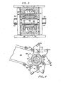
- the upper and lower transverse braces 16 Adjacent the forward extremity of the elongated main frame 10, the upper and lower transverse braces 16 are joined rigidly to the side wall 12 and 14 to support gimbal pins 24, 26 that rotatably carry an open rectangular gimbal frame which, as best shown in Figure 3, can pivot about a generally upright axis and is, in turn, arranged to pivotally support on a transverse shaft 30 the parallel side plates 32, 34 of an excavating boom, generally indicated at 36, enabling its pivotal adjustment about a transverse axis so that the excavating boom can be pivoted both vertically and transversely an amount sufficient so that its extremity can move beyond the lateral and upright contour of the described supporting frame, as indicated by phantom lines in Figures 1 and 2, thus enabling a tunnel to be excavated which will subsequently allow the passage of the entire frame therethrough.
- the side plates 32, 34 of the excavating boom 36 are held in laterally spaced relation by simple rigid metal braces 38 and the outer surfaces thereof mount balls 40, 42 for universal connection to ball sockets 44,46 at the forward ends of double-acting hydraulic rams 48, 50 whose opposite extremities are universally joined to a forward extension 10a of the main frame 10 by similar ball and socket joints 52, 54 to allow the excavating boom to be adjusted vertically or horizontally through actuation of the hydraulic rams 48, 50 by a hydraulic pump 56 that is driven by the previously described electric motor 22.
- One valve (not shown) is associated in a conventional fashion with each hydraulic ram and is arranged to supply hydraulic pressure to one or the other end of its associated ram so that, as will be apparent, if both valves are open in one direction, both hydraulic rams will extend or retract to raise or lower the excavating boom, whereas on the other hand, if one valve is open in one direction while the other is open in the opposite direction, a lateral motion of the boom will occur; for example, to the phantom-line disposition shown in Figure 2.
- Each pair of sprockets engages the enlarged opposite ends of a hinge pin 68 which is arranged in bridging relationship between the laterally-spaced sprockets to rotatably extend through a piano-hing connection in the form of interdigitated hinges 70, 72 at the front and rear of adjacent excavating buckets 74, which provide the material excavating elements of the unit.
- the enlarged ends of the pin 68 will rotate to provide only rolling friction with the engaged sprocket, thus to reduce sliding friction and extend the useful life of the elements to a considerable extent.
- each hinge pin 68 common to the foremost extremity of one bucket and the rearmost extremity of the adjacent bucket will rotate in the hinges 70, 72, thus to distribute wear and maintain the roundness of the hinge pin and the hinges.
- the line of buckets mounted on the sprockets is arranged for counterclockwise motion, as shown in Figure 1, when driven by a pair of hydraulic motors 80, 82 which are connected to opposite ends of the sprocket-mounting shaft 30 at the inner end of the bucket line by suitable gear reduction units 84, 86, such hydraulic motors each being capable of delivering as much as 150 horsepower when energized by the hydraulic pump 56 driven by the previously described electric motor 22.
- Material excavated and carried by the excavating buckets will be dumped therefrom as they pass in succession over the rear sprocket 58 onto suitable endless conveyor 88 which lies thereunder and is mounted for conveyance of material deposited thereon beyond the rear end of the frame at an upper elevation so that the material conveyed on the belt can be dumped into a suitable truck or other receptacle (not shown) for removal and subsequent processing.
- the conveyor 88 is supported between the frame plate and is powered by suitable connection to the motor 22.
Landscapes
- Engineering & Computer Science (AREA)
- Mining & Mineral Resources (AREA)
- Mechanical Engineering (AREA)
- Life Sciences & Earth Sciences (AREA)
- General Life Sciences & Earth Sciences (AREA)
- Geochemistry & Mineralogy (AREA)
- Geology (AREA)
- Earth Drilling (AREA)
- Excavating Of Shafts Or Tunnels (AREA)
- Soil Working Implements (AREA)
- Component Parts Of Construction Machinery (AREA)
- Steroid Compounds (AREA)
Applications Claiming Priority (2)
| Application Number | Priority Date | Filing Date | Title |
|---|---|---|---|
| US9302079A | 1979-11-09 | 1979-11-09 | |
| US93020 | 1979-11-09 |
Related Parent Applications (1)
| Application Number | Title | Priority Date | Filing Date |
|---|---|---|---|
| EP80303996.5 Division | 1980-11-07 |
Publications (2)
| Publication Number | Publication Date |
|---|---|
| EP0108430A1 EP0108430A1 (en) | 1984-05-16 |
| EP0108430B1 true EP0108430B1 (en) | 1986-07-30 |
Family
ID=22236388
Family Applications (2)
| Application Number | Title | Priority Date | Filing Date |
|---|---|---|---|
| EP83201298A Expired EP0108430B1 (en) | 1979-11-09 | 1980-11-07 | Continuous excavating apparatus |
| EP80303996A Expired EP0028930B1 (en) | 1979-11-09 | 1980-11-07 | Continuous excavating apparatus |
Family Applications After (1)
| Application Number | Title | Priority Date | Filing Date |
|---|---|---|---|
| EP80303996A Expired EP0028930B1 (en) | 1979-11-09 | 1980-11-07 | Continuous excavating apparatus |
Country Status (7)
| Country | Link |
|---|---|
| EP (2) | EP0108430B1 (enExample) |
| AT (1) | ATE8167T1 (enExample) |
| AU (2) | AU546996B2 (enExample) |
| CA (1) | CA1157489A (enExample) |
| DE (2) | DE8029824U1 (enExample) |
| FR (2) | FR2478159A3 (enExample) |
| IT (2) | IT8023303V0 (enExample) |
Families Citing this family (2)
| Publication number | Priority date | Publication date | Assignee | Title |
|---|---|---|---|---|
| WO2013170627A1 (zh) * | 2012-05-12 | 2013-11-21 | Liu Suhua | 一种旋转运动转变为往复冲击运动设备的方法及实施该方法的旋转运动转变为往复冲击运动设备 |
| CN111396042A (zh) * | 2020-05-19 | 2020-07-10 | 韩国辉 | 一种用于煤矿生产的具有同步抽取功能的钻机设备 |
Family Cites Families (13)
| Publication number | Priority date | Publication date | Assignee | Title |
|---|---|---|---|---|
| DE578555C (de) * | 1933-06-15 | Ida Hamel Geb Ortlieb | Untertage-Schraemfoerdermaschine | |
| FR510963A (fr) * | 1915-05-19 | 1920-12-14 | Jules Legrand | Appareil servant à creuser mécaniquement les galeries souterraines et les tranchées |
| US2320196A (en) * | 1941-06-16 | 1943-05-25 | Eugene F Smith | Tunneling machine |
| BE498215A (enExample) * | 1949-10-27 | |||
| CH314241A (fr) * | 1953-08-10 | 1956-06-15 | Scheuchzer Fils Auguste | Chaîne à fonction d'engrènement |
| DE1753989U (de) * | 1957-02-08 | 1957-10-10 | Eickhoff Geb | Gliederband. |
| US3035821A (en) * | 1958-09-12 | 1962-05-22 | Amo Placer Mines Inc | Bucket type mechanical mole |
| US3233722A (en) * | 1962-08-22 | 1966-02-08 | Charles T Jorgensen | Piano type conveyor belt |
| GB995391A (en) * | 1963-05-10 | 1965-06-16 | Himpelm Engineers Ltd | Link conveyor belts |
| DE2155590C3 (de) * | 1971-04-02 | 1974-11-07 | Friedrich Wilhelm 4222 Friedrichsfeld Paurat | Maschine zum Vortreiben von Strecken, Tunnels oder dergleichen |
| GB1393809A (en) * | 1972-06-06 | 1975-05-14 | Dobson Park Ind | Vehicle mounted mineral or eart moving or working equipment |
| US4171045A (en) * | 1978-01-20 | 1979-10-16 | The Laitram Corporation | Raised link modular conveyor belt |
| US4380354A (en) * | 1981-03-12 | 1983-04-19 | National Mine Service Company | Mining machine loading bin mounted on boom structure and method |
-
1980
- 1980-11-06 CA CA000364172A patent/CA1157489A/en not_active Expired
- 1980-11-06 AU AU64129/80A patent/AU546996B2/en not_active Ceased
- 1980-11-07 DE DE19808029824U patent/DE8029824U1/de not_active Expired
- 1980-11-07 FR FR8023933A patent/FR2478159A3/fr active Granted
- 1980-11-07 IT IT8023303U patent/IT8023303V0/it unknown
- 1980-11-07 EP EP83201298A patent/EP0108430B1/en not_active Expired
- 1980-11-07 EP EP80303996A patent/EP0028930B1/en not_active Expired
- 1980-11-07 AT AT80303996T patent/ATE8167T1/de not_active IP Right Cessation
- 1980-11-07 DE DE8080303996T patent/DE3068371D1/de not_active Expired
- 1980-11-07 IT IT8023302U patent/IT8023302V0/it unknown
-
1981
- 1981-10-23 FR FR8119989A patent/FR2493369A3/fr active Granted
-
1985
- 1985-04-19 AU AU41457/85A patent/AU570792B2/en not_active Ceased
Also Published As
| Publication number | Publication date |
|---|---|
| FR2493369A3 (fr) | 1982-05-07 |
| AU6412980A (en) | 1981-05-14 |
| AU546996B2 (en) | 1985-10-03 |
| FR2478159A3 (fr) | 1981-09-18 |
| FR2493369B3 (enExample) | 1982-11-26 |
| ATE8167T1 (de) | 1984-07-15 |
| AU570792B2 (en) | 1988-03-24 |
| DE8029824U1 (de) | 1981-04-09 |
| EP0028930B1 (en) | 1984-06-27 |
| CA1157489A (en) | 1983-11-22 |
| AU4145785A (en) | 1985-08-22 |
| IT8023303V0 (it) | 1980-11-07 |
| IT8023302V0 (it) | 1980-11-07 |
| DE3068371D1 (en) | 1984-08-02 |
| EP0108430A1 (en) | 1984-05-16 |
| FR2478159B3 (enExample) | 1982-07-02 |
| EP0028930A1 (en) | 1981-05-20 |
Similar Documents
| Publication | Publication Date | Title |
|---|---|---|
| US4157623A (en) | Conveyor folding and moldboard operation for excavating and loading systems | |
| US5228220A (en) | Bucket chain excavator | |
| US4088236A (en) | Multiple use earth working machine | |
| CN107386349A (zh) | 带有非线性挖掘组件的绳铲 | |
| EP0108430B1 (en) | Continuous excavating apparatus | |
| US4438575A (en) | Continuous excavating apparatus | |
| US3982338A (en) | Material handling apparatus | |
| US4516338A (en) | Gimbal mounted on frame with heavy metal plate sides | |
| US2844240A (en) | Wood loader | |
| US4462747A (en) | Material conveyor for use with a backhoe | |
| US4089403A (en) | Swivel assembly for a conveyor | |
| CN112061693A (zh) | 一种便于调节倒角弧度的刮板机 | |
| US6823978B2 (en) | Crawler mounted transfer station | |
| CN111807072A (zh) | 一种铲料输送机 | |
| JPS6033173Y2 (ja) | 連続掘削装置 | |
| US4053997A (en) | Scraper elevator with lower drive sprockets | |
| US2239288A (en) | Material handling apparatus | |
| US2855116A (en) | Vehicle mounted earth moving apparatus | |
| CA1177857A (en) | Bucket connection for a continuous excavating apparatus | |
| US3512282A (en) | Conveyor type loader | |
| CN116253166A (zh) | 矿用履带挖掘式装载机多功能输送装置 | |
| US2310233A (en) | Conveyor-excavator | |
| CN210763288U (zh) | 用于轮式装载机的车厢平煤装置 | |
| US2792140A (en) | Material handling machine | |
| US2002199A (en) | Loading machine |
Legal Events
| Date | Code | Title | Description |
|---|---|---|---|
| PUAI | Public reference made under article 153(3) epc to a published international application that has entered the european phase |
Free format text: ORIGINAL CODE: 0009012 |
|
| AC | Divisional application: reference to earlier application |
Ref document number: 28930 Country of ref document: EP |
|
| AK | Designated contracting states |
Designated state(s): AT CH DE FR GB IT LI NL SE |
|
| 17P | Request for examination filed |
Effective date: 19841031 |
|
| GRAA | (expected) grant |
Free format text: ORIGINAL CODE: 0009210 |
|
| AC | Divisional application: reference to earlier application |
Ref document number: 28930 Country of ref document: EP |
|
| AK | Designated contracting states |
Kind code of ref document: B1 Designated state(s): AT CH DE FR GB IT LI NL SE |
|
| PG25 | Lapsed in a contracting state [announced via postgrant information from national office to epo] |
Ref country code: IT Free format text: LAPSE BECAUSE OF FAILURE TO SUBMIT A TRANSLATION OF THE DESCRIPTION OR TO PAY THE FEE WITHIN THE PRESCRIBED TIME-LIMIT;WARNING: LAPSES OF ITALIAN PATENTS WITH EFFECTIVE DATE BEFORE 2007 MAY HAVE OCCURRED AT ANY TIME BEFORE 2007. THE CORRECT EFFECTIVE DATE MAY BE DIFFERENT FROM THE ONE RECORDED. Effective date: 19860730 Ref country code: AT Effective date: 19860730 |
|
| REF | Corresponds to: |
Ref document number: 21137 Country of ref document: AT Date of ref document: 19860815 Kind code of ref document: T |
|
| REF | Corresponds to: |
Ref document number: 3071688 Country of ref document: DE Date of ref document: 19860904 |
|
| ET | Fr: translation filed | ||
| PLBE | No opposition filed within time limit |
Free format text: ORIGINAL CODE: 0009261 |
|
| STAA | Information on the status of an ep patent application or granted ep patent |
Free format text: STATUS: NO OPPOSITION FILED WITHIN TIME LIMIT |
|
| 26N | No opposition filed | ||
| PGFP | Annual fee paid to national office [announced via postgrant information from national office to epo] |
Ref country code: GB Payment date: 19901107 Year of fee payment: 11 |
|
| PGFP | Annual fee paid to national office [announced via postgrant information from national office to epo] |
Ref country code: SE Payment date: 19901109 Year of fee payment: 11 |
|
| PGFP | Annual fee paid to national office [announced via postgrant information from national office to epo] |
Ref country code: FR Payment date: 19901120 Year of fee payment: 11 |
|
| PGFP | Annual fee paid to national office [announced via postgrant information from national office to epo] |
Ref country code: NL Payment date: 19901130 Year of fee payment: 11 |
|
| PGFP | Annual fee paid to national office [announced via postgrant information from national office to epo] |
Ref country code: DE Payment date: 19910126 Year of fee payment: 11 |
|
| PGFP | Annual fee paid to national office [announced via postgrant information from national office to epo] |
Ref country code: CH Payment date: 19910226 Year of fee payment: 11 |
|
| PG25 | Lapsed in a contracting state [announced via postgrant information from national office to epo] |
Ref country code: GB Effective date: 19911107 |
|
| PG25 | Lapsed in a contracting state [announced via postgrant information from national office to epo] |
Ref country code: SE Effective date: 19911108 |
|
| PG25 | Lapsed in a contracting state [announced via postgrant information from national office to epo] |
Ref country code: LI Effective date: 19911130 Ref country code: CH Effective date: 19911130 |
|
| PG25 | Lapsed in a contracting state [announced via postgrant information from national office to epo] |
Ref country code: NL Effective date: 19920601 |
|
| GBPC | Gb: european patent ceased through non-payment of renewal fee | ||
| NLV4 | Nl: lapsed or anulled due to non-payment of the annual fee | ||
| PG25 | Lapsed in a contracting state [announced via postgrant information from national office to epo] |
Ref country code: FR Effective date: 19920731 |
|
| REG | Reference to a national code |
Ref country code: CH Ref legal event code: PL |
|
| PG25 | Lapsed in a contracting state [announced via postgrant information from national office to epo] |
Ref country code: DE Effective date: 19920801 |
|
| REG | Reference to a national code |
Ref country code: FR Ref legal event code: ST |
|
| EUG | Se: european patent has lapsed |
Ref document number: 83201298.3 Effective date: 19920604 |