EP0108426B1 - Module for concentrating a specified gas in a gaseous mixture - Google Patents
Module for concentrating a specified gas in a gaseous mixture Download PDFInfo
- Publication number
- EP0108426B1 EP0108426B1 EP83201139A EP83201139A EP0108426B1 EP 0108426 B1 EP0108426 B1 EP 0108426B1 EP 83201139 A EP83201139 A EP 83201139A EP 83201139 A EP83201139 A EP 83201139A EP 0108426 B1 EP0108426 B1 EP 0108426B1
- Authority
- EP
- European Patent Office
- Prior art keywords
- gas
- oxygen
- module
- air
- members
- Prior art date
- Legal status (The legal status is an assumption and is not a legal conclusion. Google has not performed a legal analysis and makes no representation as to the accuracy of the status listed.)
- Expired
Links
- 239000008246 gaseous mixture Substances 0.000 title description 7
- 239000007789 gas Substances 0.000 claims description 129
- 239000001301 oxygen Substances 0.000 claims description 112
- 229910052760 oxygen Inorganic materials 0.000 claims description 112
- QVGXLLKOCUKJST-UHFFFAOYSA-N atomic oxygen Chemical compound [O] QVGXLLKOCUKJST-UHFFFAOYSA-N 0.000 claims description 110
- 239000012528 membrane Substances 0.000 claims description 59
- 239000007787 solid Substances 0.000 claims description 50
- 239000000463 material Substances 0.000 claims description 28
- 239000002131 composite material Substances 0.000 claims description 21
- XLYOFNOQVPJJNP-UHFFFAOYSA-N water Substances O XLYOFNOQVPJJNP-UHFFFAOYSA-N 0.000 claims description 16
- 238000001816 cooling Methods 0.000 claims description 9
- 239000000178 monomer Substances 0.000 claims description 6
- 239000000203 mixture Substances 0.000 claims description 5
- 229920000642 polymer Polymers 0.000 claims description 5
- 229930195735 unsaturated hydrocarbon Natural products 0.000 claims description 4
- 238000004804 winding Methods 0.000 claims description 2
- -1 polyethylene Polymers 0.000 description 20
- 239000004745 nonwoven fabric Substances 0.000 description 16
- 229910052782 aluminium Inorganic materials 0.000 description 13
- XAGFODPZIPBFFR-UHFFFAOYSA-N aluminium Chemical compound [Al] XAGFODPZIPBFFR-UHFFFAOYSA-N 0.000 description 13
- 239000004743 Polypropylene Substances 0.000 description 11
- 229920001155 polypropylene Polymers 0.000 description 11
- 238000000034 method Methods 0.000 description 9
- 238000000926 separation method Methods 0.000 description 8
- 238000004519 manufacturing process Methods 0.000 description 7
- 230000000052 comparative effect Effects 0.000 description 6
- 239000004033 plastic Substances 0.000 description 6
- 229920003023 plastic Polymers 0.000 description 6
- 239000000853 adhesive Substances 0.000 description 5
- 230000001070 adhesive effect Effects 0.000 description 5
- 229910052751 metal Inorganic materials 0.000 description 5
- 239000002184 metal Substances 0.000 description 5
- 229920000139 polyethylene terephthalate Polymers 0.000 description 5
- 239000005020 polyethylene terephthalate Substances 0.000 description 5
- OKTJSMMVPCPJKN-UHFFFAOYSA-N Carbon Chemical compound [C] OKTJSMMVPCPJKN-UHFFFAOYSA-N 0.000 description 4
- 125000006850 spacer group Chemical group 0.000 description 4
- MWUXSHHQAYIFBG-UHFFFAOYSA-N Nitric oxide Chemical compound O=[N] MWUXSHHQAYIFBG-UHFFFAOYSA-N 0.000 description 3
- 230000007423 decrease Effects 0.000 description 3
- 230000003247 decreasing effect Effects 0.000 description 3
- 230000002093 peripheral effect Effects 0.000 description 3
- 239000011148 porous material Substances 0.000 description 3
- 238000000108 ultra-filtration Methods 0.000 description 3
- IJGRMHOSHXDMSA-UHFFFAOYSA-N Atomic nitrogen Chemical compound N#N IJGRMHOSHXDMSA-UHFFFAOYSA-N 0.000 description 2
- 241000894006 Bacteria Species 0.000 description 2
- 239000004698 Polyethylene Substances 0.000 description 2
- 229920003182 Surlyn® Polymers 0.000 description 2
- 238000010276 construction Methods 0.000 description 2
- 208000037265 diseases, disorders, signs and symptoms Diseases 0.000 description 2
- 239000003822 epoxy resin Substances 0.000 description 2
- 238000010438 heat treatment Methods 0.000 description 2
- 238000010030 laminating Methods 0.000 description 2
- 150000002926 oxygen Chemical class 0.000 description 2
- 229920000647 polyepoxide Polymers 0.000 description 2
- 229920000573 polyethylene Polymers 0.000 description 2
- 229920000306 polymethylpentene Polymers 0.000 description 2
- 238000002360 preparation method Methods 0.000 description 2
- 229920005989 resin Polymers 0.000 description 2
- 239000011347 resin Substances 0.000 description 2
- 230000001225 therapeutic effect Effects 0.000 description 2
- 206010006458 Bronchitis chronic Diseases 0.000 description 1
- RYGMFSIKBFXOCR-UHFFFAOYSA-N Copper Chemical compound [Cu] RYGMFSIKBFXOCR-UHFFFAOYSA-N 0.000 description 1
- MYMOFIZGZYHOMD-UHFFFAOYSA-N Dioxygen Chemical compound O=O MYMOFIZGZYHOMD-UHFFFAOYSA-N 0.000 description 1
- 229910000737 Duralumin Inorganic materials 0.000 description 1
- 206010014561 Emphysema Diseases 0.000 description 1
- 239000004952 Polyamide Substances 0.000 description 1
- 241000220317 Rosa Species 0.000 description 1
- BZHJMEDXRYGGRV-UHFFFAOYSA-N Vinyl chloride Chemical compound ClC=C BZHJMEDXRYGGRV-UHFFFAOYSA-N 0.000 description 1
- 235000010724 Wisteria floribunda Nutrition 0.000 description 1
- 230000002159 abnormal effect Effects 0.000 description 1
- 239000011358 absorbing material Substances 0.000 description 1
- 230000000844 anti-bacterial effect Effects 0.000 description 1
- 238000009360 aquaculture Methods 0.000 description 1
- 244000144974 aquaculture Species 0.000 description 1
- 208000006673 asthma Diseases 0.000 description 1
- 230000001580 bacterial effect Effects 0.000 description 1
- 230000004888 barrier function Effects 0.000 description 1
- 206010006451 bronchitis Diseases 0.000 description 1
- 208000007451 chronic bronchitis Diseases 0.000 description 1
- 238000002485 combustion reaction Methods 0.000 description 1
- 238000011109 contamination Methods 0.000 description 1
- 238000010924 continuous production Methods 0.000 description 1
- 229910052802 copper Inorganic materials 0.000 description 1
- 239000010949 copper Substances 0.000 description 1
- 230000000994 depressogenic effect Effects 0.000 description 1
- 229910001882 dioxygen Inorganic materials 0.000 description 1
- 238000007599 discharging Methods 0.000 description 1
- 201000010099 disease Diseases 0.000 description 1
- 230000009977 dual effect Effects 0.000 description 1
- 238000001914 filtration Methods 0.000 description 1
- 239000010419 fine particle Substances 0.000 description 1
- LNEPOXFFQSENCJ-UHFFFAOYSA-N haloperidol Chemical compound C1CC(O)(C=2C=CC(Cl)=CC=2)CCN1CCCC(=O)C1=CC=C(F)C=C1 LNEPOXFFQSENCJ-UHFFFAOYSA-N 0.000 description 1
- 238000010348 incorporation Methods 0.000 description 1
- 229920000554 ionomer Polymers 0.000 description 1
- 238000003475 lamination Methods 0.000 description 1
- 238000005259 measurement Methods 0.000 description 1
- 238000013160 medical therapy Methods 0.000 description 1
- 238000002844 melting Methods 0.000 description 1
- 230000008018 melting Effects 0.000 description 1
- 239000007769 metal material Substances 0.000 description 1
- 238000002156 mixing Methods 0.000 description 1
- 229910052757 nitrogen Inorganic materials 0.000 description 1
- 230000001473 noxious effect Effects 0.000 description 1
- 235000019645 odor Nutrition 0.000 description 1
- 239000003921 oil Substances 0.000 description 1
- 238000012856 packing Methods 0.000 description 1
- 229920002647 polyamide Polymers 0.000 description 1
- 229920006289 polycarbonate film Polymers 0.000 description 1
- 210000002345 respiratory system Anatomy 0.000 description 1
- 230000000087 stabilizing effect Effects 0.000 description 1
- 229910001220 stainless steel Inorganic materials 0.000 description 1
- 239000010935 stainless steel Substances 0.000 description 1
- 230000001629 suppression Effects 0.000 description 1
- 238000002560 therapeutic procedure Methods 0.000 description 1
- 229920006305 unsaturated polyester Polymers 0.000 description 1
- QYRYFNHXARDNFZ-UHFFFAOYSA-N venlafaxine hydrochloride Chemical compound [H+].[Cl-].C1=CC(OC)=CC=C1C(CN(C)C)C1(O)CCCCC1 QYRYFNHXARDNFZ-UHFFFAOYSA-N 0.000 description 1
Images

Classifications
-
- B—PERFORMING OPERATIONS; TRANSPORTING
- B01—PHYSICAL OR CHEMICAL PROCESSES OR APPARATUS IN GENERAL
- B01D—SEPARATION
- B01D53/00—Separation of gases or vapours; Recovering vapours of volatile solvents from gases; Chemical or biological purification of waste gases, e.g. engine exhaust gases, smoke, fumes, flue gases, aerosols
- B01D53/22—Separation of gases or vapours; Recovering vapours of volatile solvents from gases; Chemical or biological purification of waste gases, e.g. engine exhaust gases, smoke, fumes, flue gases, aerosols by diffusion
-
- B—PERFORMING OPERATIONS; TRANSPORTING
- B01—PHYSICAL OR CHEMICAL PROCESSES OR APPARATUS IN GENERAL
- B01D—SEPARATION
- B01D63/00—Apparatus in general for separation processes using semi-permeable membranes
- B01D63/08—Flat membrane modules
-
- B—PERFORMING OPERATIONS; TRANSPORTING
- B01—PHYSICAL OR CHEMICAL PROCESSES OR APPARATUS IN GENERAL
- B01D—SEPARATION
- B01D63/00—Apparatus in general for separation processes using semi-permeable membranes
- B01D63/08—Flat membrane modules
- B01D63/087—Single membrane modules
-
- B—PERFORMING OPERATIONS; TRANSPORTING
- B29—WORKING OF PLASTICS; WORKING OF SUBSTANCES IN A PLASTIC STATE IN GENERAL
- B29D—PRODUCING PARTICULAR ARTICLES FROM PLASTICS OR FROM SUBSTANCES IN A PLASTIC STATE
- B29D7/00—Producing flat articles, e.g. films or sheets
- B29D7/01—Films or sheets
-
- B—PERFORMING OPERATIONS; TRANSPORTING
- B01—PHYSICAL OR CHEMICAL PROCESSES OR APPARATUS IN GENERAL
- B01D—SEPARATION
- B01D2313/00—Details relating to membrane modules or apparatus
- B01D2313/14—Specific spacers
-
- B—PERFORMING OPERATIONS; TRANSPORTING
- B01—PHYSICAL OR CHEMICAL PROCESSES OR APPARATUS IN GENERAL
- B01D—SEPARATION
- B01D2313/00—Details relating to membrane modules or apparatus
- B01D2313/22—Cooling or heating elements
-
- B—PERFORMING OPERATIONS; TRANSPORTING
- B01—PHYSICAL OR CHEMICAL PROCESSES OR APPARATUS IN GENERAL
- B01D—SEPARATION
- B01D2313/00—Details relating to membrane modules or apparatus
- B01D2313/22—Cooling or heating elements
- B01D2313/221—Heat exchangers
Definitions
- This invention relates to a module for concentrating a specified gas such as oxygen gas in a gaseous mixture such as air.
- a module comprising a plurality of members for obtaining a gas having a specified gas concentrated therein from a mixture of at least two gases, each of said members comprising (a) a support plate (b) an intermediate element providing passage for gas when the support plate is not net-like, and (c) a composite film comprised of a porous sheet-like material and one or a plurality of ultrathin solid membranes supported on the porous sheet-like material with a thickness of 5 to 500 nm (50 to 5000 A), said ultrathin solid membranes being of an addition polymer derived from at least one monomer selected from ethylenically unsaturated hydrocarbon monomers and conjugated unsaturated hydrocarbon monomers, and said composite film being laminated to one or both surfaces of the solid support plate so that the porous sheet-like material of the composite film faces the support plate; characterized in that
- the solid membrane provided by the process of EP-A-0031725 is extremely thin, and has a uniform thickness and excellent gas separating ability.
- a solid membrane produced continuously by that process and supported on a porous sheet-like material has a broad area in addition to having the aforesaid properties.
- the porous sheet-like material makes up for the weak self-supporting ability of the solid membrane, and scarcely affects the gas separation ability of the solid membrane.
- the porous sheet-like material may be any sheet-like material having a number of small pores, smoothness and self-supporting property, such as Japanese paper, nonwoven cloths, synthetic paper-like sheets, filter papers, cloths, wire nets, filtration membranes, ultrafiltration membranes, and porous films.
- Preferred porous sheet-like materials include porous polyethylene films (e.g. Celpore, a trademark for a product of Sekisui Chemical Co., Ltd.), porous polypropylene films (e.g. Celgard, a trademark for a product of Celan- ese Corporation), cellulosic ultrafiltration membranes (e.g.
- Fuji-Microfilter a trademark for a product of Fuji Film Co., Ltd
- porous polycarbonate films e.g. Nuclepore, a trademark for a product of Nomura Microscience Co., Ltd.
- polysulfone-type ultrafiltration membranes e.g. Toyo-ultrafilter, a trademark for a product of Toyo Filter Paper Co., Ltd.
- the porous polypropylene films are especially preferred because of their good adhesion to the solid membrane.
- two or more solid membranes may be supported as a laminated layer on the porous sheet-like material.
- an assembly of two solid membranes supported in a laminated layer on the porous sheet-like material exhibits excellent gas separating ability when used in separation of gases, and in most cases, shows a gas separation factor equivalent to the inherent gas separation factor of the addition polymer forming the solid membrane. It is rare therefore that more than two solid membranes should be laminated in order to obtain the desired gas separating ability.
- the continuous process of EP-A-0031725 can be carried out, for example, in the same way as described therein except that a porous sheet-like material having supported thereon one solid membrane is used instead of the porous sheet-like material.
- the porous sheet-like material having supported thereon the solid membrane (which is referred to herein as a "composite film”) can be used as prepared by the process of EP-A-0031725.
- the composite film may be heat-treated under temperature and time conditions which do not cause melting of the solid membrane (for example, in the case of heating in the atmosphere, heating is carried out at a temperature of 60 to 300°C, preferably 80 to 200°C, for a period of 3 seconds to 50 hours, preferably 5 seconds to 20 hours) to improve adhesion between the solid membrane and the porous sheet-like material.
- the solid membrane has a thickness of 5 to 300 nm (50 to 3000A).
- the module of the invention is used to obtain a gas having a specified component gas concentrated therein from a mixture of two or more gases.
- it can be used in the production of oxygen-enriched air from atmospheric air, the production of H 2 -enriched gas from a gaseous mixture containing H 2 and CO, the removal of H 2 0 from a gaseous mixture containing H 2 0, the removal of S0 2 and/or nitrogen oxide gases No x , from a gaseous mixture containing S02 and/or NO x and the production of a He-enriched gas from a gaseous mixture containing He.
- It is preferably used in the production of oxygen-enriched air (with an oxygen content of, for example 30 to 45%) from atmospheric air.
- a concentrated gas In obtaining a concentrated gas by using the module of this invention, it is only necessary to provide a difference between the partial pressures of a gas to be concentrated on the two surfaces of the solid membrane. And as the ratio (high pressure/low pressure) between the partial pressures of the gas increases, there is obtained a gas in which the gas to be concentrated is more enriched.
- the pressure of atmospheric air fed to one surface of the solid membrane can be increased to more than atmospheric pressure while the pressure at the other surface is maintained at atmospheric pressure or reduced pressure.
- the pressure of atmospheric air supplied to one surface can be maintained at atmospheric pressure while the pressure at the other surface is reduced.
- the critical feature of the module of this invention is that it has the second common gas drawing port connected to the first gas drawing port of each of the members for drawing the concentrated gas, and the pressure drop in the passage for the concentrated gas from each of the members is not more than 270 Pa (2 mmHg) per cm in a direction away from the member.
- a module of this construction is compact and light and has excellent separating efficiency.
- the support plate can be effectively used by placing the composite film on its surfaces. This means that the membrane area per member can be maximized. In other words, if the area of the solid membrane required for gas permeation is constant, the number of members can be minimized, and a compact and light-weight module can be built.
- the support plate in the module of this invention has the dual function of stabilizing the form of the members to support the composite film and either as such when the support plate is net-like or in conjunction with an intermediate element when the support plate is not net-like of forming a passage for a concentrated gas which has permeated through the solid membrane. If the gas has difficulty flowing through the passage, the pressure drop increases, and therefore, the difference between the pressures exerted on both surfaces of the solid membrane is small. Hence, the amount of the gas permeated decreases proportionally to such a difference in pressure.
- the support plate is suitably of a structure which minimizes hampering of the passage for the concentrated gas which has permeated through the solid membrane, namely a structure which minimizes the pressure drop.
- the pressure drop is measured in this invention in the following manner.
- a sample having a length of 50 cm and a width of 25 cm is cut out from the member, and the entire surface of the sample is covered with a gas- barrier film. Both 50 cm-long ends of the sample are sealed gas-tight. To both 25 cm-long ends is connected a thick tubular flow opening through which a gas flows without resistance, for example a tube having an inside diameter of about 8 mm. One end of the tube is kept open and adapted for decreasing the opening area, and vacuum suction is effected from the other opening of the tube. When the flow rate of air is 1 liter/min. on the suction side, the pressures at both openings are measured, and the difference between them is defined as the pressure drop. The measurement is made at 25°C.
- the support plate in the module of this invention is preferably a metal plate such as an aluminum plate, a Duralmin (tradename) plate, a plastic plate such as a polypropylene, hard vinyl chloride resin, fiber-reinforced polyethylene terephthalate or unsaturated polyester plate, or a net-like article such as stainless steel net or porous polypropylene plate.
- a metal plate or plastic plate other than the net-like article is used as the support plate
- an intermediate element is used which forms a sufficient passage for a concentrated gas between the support plate and the composite film.
- the intermediate element may also be used when the solid support plate is a net-like article.
- Various kinds of nets, nonwoven fabrics or porous materials can be used as the intermediate element.
- a member containing such an intermediate element can be built by laminating the net or nonwoven fabric, for example, either alone or in combination on one or both surfaces of the support plate, and further laminating the composite film onto the intermediate element. It is necessary in this case to laminate these materials such that the pressure drop in each member is within the above-specified range.
- the intermediate element acts to render the flow of a gas through the member easy when a net-like article is not used as the support plate, and its selection is especially important.
- the net preferably has coarse meshes and a raised-and- depressed pattern. It may be made of a plastic or metal, and plastic nets are preferred from the viewpoint of light weight.
- the plastic nets preferably have stiffness, and for this purpose, such materials as polypropylene, polyethylene terephthalate and polyamides may be used. Examples of commercially available nets are Vexor of Du Pont, Netlon of Tokyo Polymer Co., Ltd., and Nip nets of N.B.C. Industrial Co.
- the nonwoven fabrics may be made from, for example, polyethylene terephthalate, polypropylene, polyethylene orpolyamides.
- polyethylene terephthalate polypropylene
- polyethylene orpolyamides polyethylene orpolyamides.
- Unicell R Type of Teijin Limited and MF Type of Japan Vilene are commercially available.
- a preferred laminated structure in the member of the module of this invention consists of a metal plate, a net-like material on both surfaces of the metal plate, a non-woven fabric on both surfaces of the net-like material and a composite film laminated to the surfaces of the nonwoven fabric so that the porous sheet-like material contacts the non-woven fabric.
- a member of this structure shows an especially small pressure drop, has good durability and prevents deformation of the solid membrane.
- the use of the non- woven fabric is advantageous in avoiding rupture of the solid membrane which may occur in the absence of a nonwoven fabric as a result of deformation of the solid membrane along the profile of the net-like material (generally having coarse meshes and an uneven surface).
- the nonwoven fabric also has an action of making the flow of a gas easy. Accordingly, it is preferred that the nonwoven fabric should have a smooth surface and a smaller mesh opening size than the mesh opening size of the net-like material.
- the thickness of the member should preferably be as small as possible. It is generally not more than 5 mm, preferably not more than 4 mm, more preferably not more than 3 mm.
- the member used in the module of this invention preferably has the composite film on both surfaces of one support plate.
- a first gas drawing port is provided in this member in order to draw together the concentrated gas obtained after permeation through the two composite films.
- the first drawing port should have a cross-sectional area and a length which scarcely permit a pressure drop therein.
- the member having one drawing port for the two solid membranes is characterised by the fact that the number of drawing ports can be reduced to one-half as compared with a member having two drawing ports for two solid membranes, and the number of assembling pipes for assembling the concentrated gas from the drawing ports can be decreased, thus imparting a simple and convenient structure to the member and the module.
- adhesives are preferably used.
- preferred adhesives are epoxy resins, and an ionomer resin (Surlyn A@) formed into a film.
- an adhesive in a film form for instance, Surlyn A@ film
- uniform thickness and good gas-tightness can be achieved.
- a plurality of members so produced are built into an array of the stacked members so as to prevent contact of the solid membranes with each other and also to provide a passage through which a gas flows along the outside surface of the solid membrane.
- the interval between the members is at least 1 mm, preferably at least 2 mm.
- a preferred array for the production of the module of this invention is the one in which the members at two opposite ends are composed of a support plate and the composite film laminated only to its one surface so as to avoid exposure of the solid membrane surfaces.
- Spacers of any material are used between the members in building the array.
- the spacers are preferably made of a rubber or a plastic. It is sufficient that the spacers are located at the peripheral edges of the members, and are fixed to the member by, for example, an adhesive.
- the array so built is then placed into a box capable of receiving it to provide the module of this invention.
- the first gas drawing ports from the individual members are connected to a single assembling pipe.
- One end portion of the assembling pipe is drawn from the box to form a second gas drawing port from which the concentrated gas is drawn off.
- the box further includes a common feed port for feeding a gas to be concentrated from outside the box, and a third common drawing port for drawing the gas remaining after drawing off the concentrated gas.
- the gas to be concentrated which has been fed into the box from the common feed port is concentrated through the solid membranes of the members while it flows through the passages between the members, thereby giving a concentrated gas (which is drawn out of the box through the second common drawing port) to the inside of the solid membrane, while the remaining gas is discharged from the box through the third common drawing port.
- the arrangement of the drawing ports for each member, the common feed port and third common drawing port is such that the gas to be concentrated which is flowing through the passages between the members of the array forms a flow which is countercurrent (for example, as shown in Figure 2, the gas to be concentrated is introduced into the passage between the members from the direction of the first gas drawing port), or is angularly displaced (i.e. not concurrent), to the flowing direction of the concentrated gas given to the inside of the solid membrane.
- the module of this invention has an improved separating efficiency.
- the module of this invention is advantageously used when a gas to be concentrated is fed at atmospheric pressure from the common feed port, and the second common drawing port from which the concentrated gas is drawn off is connected to a pressure reduction system to reduce the pressure of the passage for the concentrated gas.
- a module is light in weight and compact.
- the amount of the air to be fed to the module is usually at least 5 times, preferably at least 10 times, more preferably at least 30 times, the amount of oxygen-enriched air drawn from the module.
- An apparatus for obtaining oxygen-enriched air from the atmospheric air using the module of this invention is embodied by an oxygen enricher provided by this invention.
- an oxygen-enricher for obtaining an oxygen-enriched gas from air comprising a module including an array of a plurality of members for obtaining the oxygen-enriched gas from the air, an air feed port for feeding the air into the module, an air exhaust port for drawing a gas of a reduced oxygen concentration from the module, a vacuum pump for reducing the pressure on oxygen-enriched gas in the members of the array and withdrawing the oxygen-enriched gas therefrom through a tube, cooling and water-removing means for lowering the temperature of the oxygen-enriched gas from the vacuum pump and removing water therefrom, and a housing; characterised in that
- the oxygen-enriched air (gas) obtained by the oxygen enricher of this invention can be used therapeutically for patients with diseases of the respiratory system such as asthma, emphysema and chronic bronchitis, and for industrial applications in small-size combustion furnaces and aquaculture.
- the oxygen enricher of this invention is characterised by being light in weight and compact, producing little noise, and being able to produce oxygen-enriched air having a small temperature difference from the temperature of the atmospheric air and having an oxygen concentration of not more than 50%. Accordingly, the oxygen-enriched air obtained from the oxygen enricher of this invention is especially recommended for use in medical therapy.
- oxygen-enriched air having an oxygen concentration of more than 60% is known to cause pneumonic ailments or nervous disorders rather than to perform therapy. It is also known that oxygen-enriched air having a large temperature difference from the temperature of the atmospheric air gives an unpleasant feeling to patients. Evidently, a heavy, bulky and noise- making device is inappropriate.
- incorporación of the module into the oxygen enricher can be achieved not only by setting the module of this invention therein, but also providing the aforesaid array before the building of the module of this invention in a preselected area in the oxygen enricher.
- the oxygen enricher of this invention includes those in which the module has been incorporated by any of these methods.
- the fan takes the air from the air feed opening, supplies it to the module and discharges it from the discharge opening.
- the vacuum pump reduces the pressure of the passages for the oxygen-enriched air in the module and takes the oxygen-enriched air out of the oxygen enricher so that concentration is effected with good efficiency through the solid membranes.
- the gas having a reduced oxygen concentration as a result of going through the module is discharged from the air exhaust port after it has cooled the vacuum pump.
- the oxygen-enriched air from the vacuum pump is taken out of the oxygen enricher, it is cooled with the atmospheric air taken into the oxygen enricher from the air feed opening and the water is removed therefrom.
- the cooling and water removing means may, for example, be a hose through which oxygen-enriched air can flow.
- the cooled oxygen-enriched air is taken out of the oxygen enricher without heat exchange with the hot gas to be discharged which has cooled the vacuum pump.
- the fan used in this invention should be capable of supplying atmospheric air into the module in an amount at least 5 times, preferably at least 10 times, more preferably at least 30 times, the amount of oxygen-enriched air to be drawn off from the module.
- a suitable example of the vacuum pump is one which does not permit inclusion of fine particles such as oils because the resulting oxygen-enriched air is used for human inhalation.
- a preferred vacuum pump is of the oilless type with noise suppression and good durability. The ability of the pump varies greatly depending upon the amount of enriched air, the concentration of oxygen, and the performance of the separating membrane. For example, when it is desired to obtain oxygen-enriched air having an oxygen concentration of at least 35% at 6 liters/ min.
- the pump is required to have such a performance as can secure a flow rate of 6 liters/min. at an absolute pressure of 36 kPa (270 mmHg).
- oilless pumps of the diaphragm type made by Gast Corp. and Thomas Corp. of U.S.A. and Iwai Kabushiki Kais- ha of Japan, for example, are used preferably.
- the gas to be discharged from the module can be utilized for the cooling of the vacuum pump in operation.
- the cooled gas is discharged out of the oxygen enricher through an air duct having at least one winding portion in order to prevent leakage of the pump noises from the oxygen enricher. It is also preferred to apply a sound absorbing material, for example, to the wall of the housing around the pump.
- a heat exchanger such as a hose is used as the cooling and water-separating means.
- a heat exchanger such as a hose is used as the cooling and water-separating means.
- the heat exchanger In order to cool the oxygen-enriched air with good efficiency by the atmospheric air to a point near the temperature of the atmospheric air through the heat exchanger it is preferred to provide the heat exchanger immediately near the airfeed opening. Care should be taken so that the surrounding of the heat exchanger is not warmed by the heat of the vacuum pump.
- the heat exchanger is preferably made of metallic material.
- a copper material is especially preferred because it also has an antibacterial effect.
- the heat exchanger may be of any of ordinary types. A preferred type is the one which is compact and permits flowing of water therethrough. Accordingly, a coil-like heat exchanger is preferred.
- the length of the heat exchanger differs depending upon the amount and temperature of the enriched air. In some cases, the length of the coil is desirably more than 1 meter.
- the water-separating means serves to separate the water from the enriched air.
- the simplest means is to introduce water-containing enriched air from a side portion of a cylindrical tube, and separating the air upwardly and the moisture downwardly.
- a packing such as a Raschig ring may be put into the cylindrical tube, and it is also possible to provide an obstacle such as a shelf therein.
- the water which gathers in the lower portion of the water separator is discharged out of it.
- the manner of discharging is not particularly restricted. For example, a receiver tray is provided to pool the water therein. Or the water is caused to be absorbed by a material capable of well absorbing water, such as a gauze, and then is evaporated. In the latter case, water can be evaporated efficiently by using the exhaust gas which has been used to cool the pump.
- the oxygen enricher may also include a column packed with activated carbon for example for removing noxious gases such as NO x and SO X and offensive odors from the enriched air, or a biofilter for removing bacteria from the enriched air. This is also effective for preventing bacterial contamination in the conduit portion for enriched air when the oxygen enricher is out of operation.
- the oxygen enricher may also include accessory parts such as alarms for detecting and warning an abnormal condition during the operation, timers, flow meters, manometers, etc.
- Figure 1 of the accompanying drawings is a schematic perspective view illustrating the structure of this member.
- a cut 42 having a width of 6 mm and a length of 40 mm was provided in one 250 mm-long side of the aluminum plate 41.
- a drawing tube 44 for giving a gas drawing port 43 for drawing off a concentrated gas was fixed to the cut 42.
- the drawing tube 44 was built by providing a cylindrical metallic tube having a thickness of 0.3 mm, an outside diameter of 3.3 mm and a length of 75 mm, and collapsing a 50 mm-long portion of the tube from one end thereof until that portion had a thickness of 1.2 mm (the collapsed portion had a width of 4.5 mm).
- the collapsed portion was inserted into the cut 42 of the aluminum plate 41 as shown in Figure 1, and an epoxy resin was filled in the space formed between the aluminum plate and the drawing tube to fix the drawing tube to the aluminum plate.
- the end 45 of the collapsed portion of the drawing tube 44 was positioned so that it formed a clearance of more than about 5 mm from the deepest part of the cut.
- a gas concentrated by the solid membrane is collected by the drawing tube 44 from the end 45 through this clearance, and is drawn off from the drawing port 43.
- the net 46, the nonwoven fabric 47 and a composite film 48 were laminated as shown in Figure 1 to both surfaces of the aluminum plate 41 having the drawing tube 44 fixed thereto.
- the aluminum plate, the net, the nonwoven fabric and . solid membrane were fixed at their peripheral edge portion by an adhesive applied in a width of 15 mm so as to prevent air leakage from the peripheral edge.
- the basic member for gas concentration showed a pressure drop of less than 80 Pa (0.6 mmHg) per cm.
- Drawing ports 43 from the individual members of the array 51 were connected to one assembling tube 52, and the entire structure was placed in a box 50.
- Figure 2 of the accompanying drawings shows a schematic perspective view of the module of this invention in which the array 51 was placed in the box 50.
- the reference numeral 52 represents the assembling tube connected to the first drawing tubes 44 of the individual members
- the reference numeral 53 represents a second common drawing port.
- the reference numeral 54 represents a common feed port for feeding a gas to be concentrated to the members
- 55 a third common drawing port for drawing the remaining gas formed as a result of concentration.
- the arrows show the flow of the gas.
- a gas fed from the common feed port in the direction of arrow (a) passed through the individual members of the array 51, and was withdrawn as the remaining gas from the third common drawing port 55 in the direction of arrow (b).
- the fed gas was concentrated during passage through the members, and the concentrated gas was collected by the assembling tube 52 through the first drawing tubes 44, and drawn off from the second common drawing port 53.
- Oxygen-enriched air was produced from the air using the module constructed as above.
- the second common drawing port 53 was connected to a vacuum pump (not shown), and while reducing the pressure, air was fed from the common feed opening port 54 at a rate of 0.3 m 3 /min.
- Oxygen-enriched air having an oxygen content of 41.7% by volume was obtained at a rate of 7 liters/ min. from the vacuum pump.
- the members showed a pressure drop of 1.3 kPa (9.4 mmHg) per cm.
- a module was built in the same way as in Example 1 using these members. Air was separated by using the module. When the module was operated while maintaining the pressure of the assembling tube 52 at 26.5 kPa (190 mmHg) ab., oxygen-enriched air having an oxygen content of 26.7% by volume was obtained at a rate of 2.9 liters/min.
- An oxygen enricher was built by incorporating the module shown in Example 1 (see Figures 1 and 2).
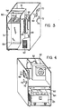
- FIGs 3 and 4 are schematic perspective views of the oxygen enricher of this invention. In these figures, the top and that side surface which appears in front on the sheet surface of these drawings are removed. Figure 4 shows the same oxygen enricher as in Figure 3 except that the rear side and the front side in Figure 3 are reversed.
- the reference numeral 51 represents an array of a plurality of laminated members including the solid membranes, and 52, an assembling tube connected to the oxygen-enriched air drawing ports ofthe individual members.
- the reference numeral 60 represents a module section having the array 51 therein with an air feed port 54 and a discharge port 55 for the remaining gas.
- the atmospheric air taken into the oxygen enricher from the airtake-in port 62 by the rotation of fan 61 rose in contact with a cooler 63 through which the oxygen-enriched air was passed, and went past the fan 61. Then, it was introduced into the module from air feed port 54 of the module 60 and passed through the array 51. Then, it left the module from the exhaust port 55 of the module (see Figure 3). Then, it entered a pump chamber 64 to cool a pump 65, and without heat exchange with oxygen-enriched air, was discharged out of the oxygen enricher via a discharge path.
- the discharge path 66 was independent so that itwas kept from contact with electrical instruments (not shown Fig. 4).
- the reference numerals 70, 71, 72 and 73 respectively represent a switch button for electric power, a flow meter, a pressure gauge and a timer.
- the oxygen enricher had a width of 330 mm, a length of 380 mm, a height of 700 mm (the side having the air drawing port 69 was regarded as the front surface), and a weight of 40 kg.
- oxygen-enriched air having an oxygen concentration of 41.7% was obtained at a rate of 7 liters/ min.
- the temperature of oxygen-enriched air at an absolute pressure of 21.3 kPa (160 mmHg) was 15.4°C which was nearly the same as the temperature of the room.
- the noise during the operation was 43 horn at a place 1 meter away from the oxygen enricher.
- Example 2 For comparison, an oxygen enricher was builtas in Example 2 but using the module obtained in Comparative Example 1 which did not contain a polypropylene net.
- oxygen enriched air having an oxygen concentration of 26.7% was obtained at a rate of 2.9 liters/min.
Description
- This invention relates to a module for concentrating a specified gas such as oxygen gas in a gaseous mixture such as air.
- Devices for obtaining an oxygen-enriched gas from air are disclosed in US-A-3976451 and 4174955, while US-A-4155793 describes a process for preparing a composite laminar membrane for use in such devices. US-A-4132824 and 4192842 describe the preparation of ultrathin membranes for use in gas separations. In European Patent Application EP-A-0031725 (published 8 July 1981), from which this Application is divided, we describe the preparation of ultrathin solid membranes of uniform thickness having gas separation factors substantially equivalent to the inherent gas separation factor of the addition polymer from which they are made.
- According to the present invention we provide a module comprising a plurality of members for obtaining a gas having a specified gas concentrated therein from a mixture of at least two gases, each of said members comprising (a) a support plate (b) an intermediate element providing passage for gas when the support plate is not net-like, and (c) a composite film comprised of a porous sheet-like material and one or a plurality of ultrathin solid membranes supported on the porous sheet-like material with a thickness of 5 to 500 nm (50 to 5000 A), said ultrathin solid membranes being of an addition polymer derived from at least one monomer selected from ethylenically unsaturated hydrocarbon monomers and conjugated unsaturated hydrocarbon monomers, and said composite film being laminated to one or both surfaces of the solid support plate so that the porous sheet-like material of the composite film faces the support plate; characterized in that
- (1) each of said members is sealed gas-tight around the periphery except for a passage to a first gas drawing port for drawing off the gas having a specified gas concentrated therein, and the pressure drop in the passage for concentrated gas from each member is not more than 270 Pa (2 mmHg) per cm in a direction away from the member,
- (2) the module has a common feed port for feeding the mixture of at least two gases to the solid membrane surface of each member, a second common drawing port connected to the first gas drawing port of each of said members, and a third common drawing port for drawing off the remaining gases formed as a result of concentration by each of the members, and
- (3) the passage in each of the members to the first gas drawing port is positioned closer to the common feed port than to the third common drawing port.
- The solid membrane provided by the process of EP-A-0031725 is extremely thin, and has a uniform thickness and excellent gas separating ability. In particular, a solid membrane produced continuously by that process and supported on a porous sheet-like material has a broad area in addition to having the aforesaid properties. The porous sheet-like material makes up for the weak self-supporting ability of the solid membrane, and scarcely affects the gas separation ability of the solid membrane.
- The porous sheet-like material may be any sheet-like material having a number of small pores, smoothness and self-supporting property, such as Japanese paper, nonwoven cloths, synthetic paper-like sheets, filter papers, cloths, wire nets, filtration membranes, ultrafiltration membranes, and porous films. Preferred porous sheet-like materials include porous polyethylene films (e.g. Celpore, a trademark for a product of Sekisui Chemical Co., Ltd.), porous polypropylene films (e.g. Celgard, a trademark for a product of Celan- ese Corporation), cellulosic ultrafiltration membranes (e.g. Fuji-Microfilter, a trademark for a product of Fuji Film Co., Ltd), porous polycarbonate films (e.g. Nuclepore, a trademark for a product of Nomura Microscience Co., Ltd.), and polysulfone-type ultrafiltration membranes (e.g. Toyo-ultrafilter, a trademark for a product of Toyo Filter Paper Co., Ltd.). The porous polypropylene films are especially preferred because of their good adhesion to the solid membrane.
- If desired, two or more solid membranes may be supported as a laminated layer on the porous sheet-like material. Particularly, an assembly of two solid membranes supported in a laminated layer on the porous sheet-like material exhibits excellent gas separating ability when used in separation of gases, and in most cases, shows a gas separation factor equivalent to the inherent gas separation factor of the addition polymer forming the solid membrane. It is rare therefore that more than two solid membranes should be laminated in order to obtain the desired gas separating ability. To superimpose two or more solid membranes on the porous sheet-like material, the continuous process of EP-A-0031725 can be carried out, for example, in the same way as described therein except that a porous sheet-like material having supported thereon one solid membrane is used instead of the porous sheet-like material.
- The porous sheet-like material having supported thereon the solid membrane (which is referred to herein as a "composite film") can be used as prepared by the process of EP-A-0031725. Alternatively before use the composite film may be heat-treated under temperature and time conditions which do not cause melting of the solid membrane (for example, in the case of heating in the atmosphere, heating is carried out at a temperature of 60 to 300°C, preferably 80 to 200°C, for a period of 3 seconds to 50 hours, preferably 5 seconds to 20 hours) to improve adhesion between the solid membrane and the porous sheet-like material.
- The solid membrane has a thickness of 5 to 300 nm (50 to 3000A).
- The module of the invention is used to obtain a gas having a specified component gas concentrated therein from a mixture of two or more gases. For example, it can be used in the production of oxygen-enriched air from atmospheric air, the production of H2-enriched gas from a gaseous mixture containing H2 and CO, the removal of H20 from a gaseous mixture containing H20, the removal of S02 and/or nitrogen oxide gases Nox, from a gaseous mixture containing S02 and/or NOx and the production of a He-enriched gas from a gaseous mixture containing He. It is preferably used in the production of oxygen-enriched air (with an oxygen content of, for example 30 to 45%) from atmospheric air.
- In obtaining a concentrated gas by using the module of this invention, it is only necessary to provide a difference between the partial pressures of a gas to be concentrated on the two surfaces of the solid membrane. And as the ratio (high pressure/low pressure) between the partial pressures of the gas increases, there is obtained a gas in which the gas to be concentrated is more enriched. For example, in the production of oxygen-enriched air from the atmospheric air, the pressure of atmospheric air fed to one surface of the solid membrane can be increased to more than atmospheric pressure while the pressure at the other surface is maintained at atmospheric pressure or reduced pressure. Alternatively the pressure of atmospheric air supplied to one surface can be maintained at atmospheric pressure while the pressure at the other surface is reduced.
- The critical feature of the module of this invention is that it has the second common gas drawing port connected to the first gas drawing port of each of the members for drawing the concentrated gas, and the pressure drop in the passage for the concentrated gas from each of the members is not more than 270 Pa (2 mmHg) per cm in a direction away from the member. A module of this construction is compact and light and has excellent separating efficiency.
- In the members of the module of this invention, the support plate can be effectively used by placing the composite film on its surfaces. This means that the membrane area per member can be maximized. In other words, if the area of the solid membrane required for gas permeation is constant, the number of members can be minimized, and a compact and light-weight module can be built.
- The support plate in the module of this invention has the dual function of stabilizing the form of the members to support the composite film and either as such when the support plate is net-like or in conjunction with an intermediate element when the support plate is not net-like of forming a passage for a concentrated gas which has permeated through the solid membrane. If the gas has difficulty flowing through the passage, the pressure drop increases, and therefore, the difference between the pressures exerted on both surfaces of the solid membrane is small. Hence, the amount of the gas permeated decreases proportionally to such a difference in pressure.
- It is known that separation of a gaseous mixture becomes better (the gas separating ability is better) as the ratio of the pressures exerted on both surfaces of the solid membrane (the ratio of the pressure on the higher pressure side to the pressure on the lower pressure side) increases. Accordingly, when the pressure drop in the passage is high, the pressure on the lower pressure side increases and the ratio of the pressures decreases. Consequently, the concentration of the desired gas in the concentrated gas obtained after permeation through the solid membrane decreases.
- For this reason, the support plate is suitably of a structure which minimizes hampering of the passage for the concentrated gas which has permeated through the solid membrane, namely a structure which minimizes the pressure drop. A member in which the pressure drop in a passage for concentrated gas is not more than 270 Pa (2 mmHg), preferably not more than 200 Pa (1.5 mmHg), more preferably not more than 130 Pa (1 mmHg), per cm is required.
- The pressure drop is measured in this invention in the following manner.
- A sample having a length of 50 cm and a width of 25 cm is cut out from the member, and the entire surface of the sample is covered with a gas- barrier film. Both 50 cm-long ends of the sample are sealed gas-tight. To both 25 cm-long ends is connected a thick tubular flow opening through which a gas flows without resistance, for example a tube having an inside diameter of about 8 mm. One end of the tube is kept open and adapted for decreasing the opening area, and vacuum suction is effected from the other opening of the tube. When the flow rate of air is 1 liter/min. on the suction side, the pressures at both openings are measured, and the difference between them is defined as the pressure drop. The measurement is made at 25°C.
- The support plate in the module of this invention is preferably a metal plate such as an aluminum plate, a Duralmin (tradename) plate, a plastic plate such as a polypropylene, hard vinyl chloride resin, fiber-reinforced polyethylene terephthalate or unsaturated polyester plate, or a net-like article such as stainless steel net or porous polypropylene plate. When a metal plate or plastic plate other than the net-like article is used as the support plate, an intermediate element is used which forms a sufficient passage for a concentrated gas between the support plate and the composite film. The intermediate element may also be used when the solid support plate is a net-like article. Various kinds of nets, nonwoven fabrics or porous materials can be used as the intermediate element. A member containing such an intermediate element can be built by laminating the net or nonwoven fabric, for example, either alone or in combination on one or both surfaces of the support plate, and further laminating the composite film onto the intermediate element. It is necessary in this case to laminate these materials such that the pressure drop in each member is within the above-specified range.
- The intermediate element acts to render the flow of a gas through the member easy when a net-like article is not used as the support plate, and its selection is especially important. The net preferably has coarse meshes and a raised-and- depressed pattern. It may be made of a plastic or metal, and plastic nets are preferred from the viewpoint of light weight. The plastic nets preferably have stiffness, and for this purpose, such materials as polypropylene, polyethylene terephthalate and polyamides may be used. Examples of commercially available nets are Vexor of Du Pont, Netlon of Tokyo Polymer Co., Ltd., and Nip nets of N.B.C. Industrial Co.
- The nonwoven fabrics may be made from, for example, polyethylene terephthalate, polypropylene, polyethylene orpolyamides. For example, Unicell R Type of Teijin Limited, and MF Type of Japan Vilene are commercially available.
- A preferred laminated structure in the member of the module of this invention consists of a metal plate, a net-like material on both surfaces of the metal plate, a non-woven fabric on both surfaces of the net-like material and a composite film laminated to the surfaces of the nonwoven fabric so that the porous sheet-like material contacts the non-woven fabric. A member of this structure shows an especially small pressure drop, has good durability and prevents deformation of the solid membrane. In particular, the use of the non- woven fabric is advantageous in avoiding rupture of the solid membrane which may occur in the absence of a nonwoven fabric as a result of deformation of the solid membrane along the profile of the net-like material (generally having coarse meshes and an uneven surface). The nonwoven fabric also has an action of making the flow of a gas easy. Accordingly, it is preferred that the nonwoven fabric should have a smooth surface and a smaller mesh opening size than the mesh opening size of the net-like material.
- To make the entire module compact, the thickness of the member should preferably be as small as possible. It is generally not more than 5 mm, preferably not more than 4 mm, more preferably not more than 3 mm.
- As stated hereinabove, the member used in the module of this invention preferably has the composite film on both surfaces of one support plate. A first gas drawing port is provided in this member in order to draw together the concentrated gas obtained after permeation through the two composite films. The first drawing port should have a cross-sectional area and a length which scarcely permit a pressure drop therein. The member having one drawing port for the two solid membranes is characterised by the fact that the number of drawing ports can be reduced to one-half as compared with a member having two drawing ports for two solid membranes, and the number of assembling pipes for assembling the concentrated gas from the drawing ports can be decreased, thus imparting a simple and convenient structure to the member and the module.
- Excepting the passage to the drawing port, the entire periphery of the member is sealed up gas-tight. In other words, it is necessary to provide a structure which does not permit mixing of a feed gas and the concentrated gas which has permeated through the solid membrane. To provide such a structure adhesives are preferably used. Examples of preferred adhesives are epoxy resins, and an ionomer resin (Surlyn A@) formed into a film. When an adhesive in a film form (for instance, Surlyn A@ film) is used, uniform thickness and good gas-tightness can be achieved.
- A plurality of members so produced are built into an array of the stacked members so as to prevent contact of the solid membranes with each other and also to provide a passage through which a gas flows along the outside surface of the solid membrane. The interval between the members is at least 1 mm, preferably at least 2 mm. A preferred array for the production of the module of this invention is the one in which the members at two opposite ends are composed of a support plate and the composite film laminated only to its one surface so as to avoid exposure of the solid membrane surfaces.
- Spacers of any material are used between the members in building the array. From the viewpoint of the light weight of the module or the firmness of the members, the spacers are preferably made of a rubber or a plastic. It is sufficient that the spacers are located at the peripheral edges of the members, and are fixed to the member by, for example, an adhesive.
- The array so built is then placed into a box capable of receiving it to provide the module of this invention. In the array within the box, the first gas drawing ports from the individual members are connected to a single assembling pipe. One end portion of the assembling pipe is drawn from the box to form a second gas drawing port from which the concentrated gas is drawn off.
- The box further includes a common feed port for feeding a gas to be concentrated from outside the box, and a third common drawing port for drawing the gas remaining after drawing off the concentrated gas.
- The gas to be concentrated which has been fed into the box from the common feed port is concentrated through the solid membranes of the members while it flows through the passages between the members, thereby giving a concentrated gas (which is drawn out of the box through the second common drawing port) to the inside of the solid membrane, while the remaining gas is discharged from the box through the third common drawing port.
- The arrangement of the drawing ports for each member, the common feed port and third common drawing port is such that the gas to be concentrated which is flowing through the passages between the members of the array forms a flow which is countercurrent (for example, as shown in Figure 2, the gas to be concentrated is introduced into the passage between the members from the direction of the first gas drawing port), or is angularly displaced (i.e. not concurrent), to the flowing direction of the concentrated gas given to the inside of the solid membrane. By forming such a flow,.the module of this invention has an improved separating efficiency.
- The module of this invention is advantageously used when a gas to be concentrated is fed at atmospheric pressure from the common feed port, and the second common drawing port from which the concentrated gas is drawn off is connected to a pressure reduction system to reduce the pressure of the passage for the concentrated gas. Such a module is light in weight and compact.
- When, for example, oxygen-enriched air is produced from atmospheric air, the amount of the air to be fed to the module is usually at least 5 times, preferably at least 10 times, more preferably at least 30 times, the amount of oxygen-enriched air drawn from the module.
- An apparatus for obtaining oxygen-enriched air from the atmospheric air using the module of this invention is embodied by an oxygen enricher provided by this invention.
- Thus, according to the invention there is provided an oxygen-enricher for obtaining an oxygen-enriched gas from air comprising a module including an array of a plurality of members for obtaining the oxygen-enriched gas from the air, an air feed port for feeding the air into the module, an air exhaust port for drawing a gas of a reduced oxygen concentration from the module, a vacuum pump for reducing the pressure on oxygen-enriched gas in the members of the array and withdrawing the oxygen-enriched gas therefrom through a tube, cooling and water-removing means for lowering the temperature of the oxygen-enriched gas from the vacuum pump and removing water therefrom, and a housing; characterised in that
- (1) the module is a module of the invention,
- (2) a fan is provided in front of the air feed port of the module and drawing therefrom a gas having a reduced oxygen concentration,
- (3) said vacuum pump is adapted to be cooled by the gas having a reduced oxygen concentration which has left the array, and
- (4) a passage is provided through which the oxygen-enriched gas from the vacuum pump flows while it is cooled fully by the cooling and water-removing means cooled by the air taken into the oxygen enricher from the air feed port, and. the cooled oxygen-enriched gas is then drawn out of the oxygen enricher without heat exchange with the gas having a reduced oxygen concentration which has cooled the vacuum pump.
- The oxygen-enriched air (gas) obtained by the oxygen enricher of this invention can be used therapeutically for patients with diseases of the respiratory system such as asthma, emphysema and chronic bronchitis, and for industrial applications in small-size combustion furnaces and aquaculture. The oxygen enricher of this invention is characterised by being light in weight and compact, producing little noise, and being able to produce oxygen-enriched air having a small temperature difference from the temperature of the atmospheric air and having an oxygen concentration of not more than 50%. Accordingly, the oxygen-enriched air obtained from the oxygen enricher of this invention is especially recommended for use in medical therapy.
- Inhalation of oxygen-enriched air having an oxygen concentration of more than 60% is known to cause pneumonic ailments or nervous disorders rather than to perform therapy. It is also known that oxygen-enriched air having a large temperature difference from the temperature of the atmospheric air gives an unpleasant feeling to patients. Evidently, a heavy, bulky and noise- making device is inappropriate.
- Incorporation of the module into the oxygen enricher can be achieved not only by setting the module of this invention therein, but also providing the aforesaid array before the building of the module of this invention in a preselected area in the oxygen enricher. The oxygen enricher of this invention includes those in which the module has been incorporated by any of these methods.
- The fan takes the air from the air feed opening, supplies it to the module and discharges it from the discharge opening.
- The vacuum pump reduces the pressure of the passages for the oxygen-enriched air in the module and takes the oxygen-enriched air out of the oxygen enricher so that concentration is effected with good efficiency through the solid membranes.
- In the oxygen enricher, the gas having a reduced oxygen concentration as a result of going through the module is discharged from the air exhaust port after it has cooled the vacuum pump. Before the oxygen-enriched air from the vacuum pump is taken out of the oxygen enricher, it is cooled with the atmospheric air taken into the oxygen enricher from the air feed opening and the water is removed therefrom. The cooling and water removing means may, for example, be a hose through which oxygen-enriched air can flow. The cooled oxygen-enriched air is taken out of the oxygen enricher without heat exchange with the hot gas to be discharged which has cooled the vacuum pump.
- The fan used in this invention should be capable of supplying atmospheric air into the module in an amount at least 5 times, preferably at least 10 times, more preferably at least 30 times, the amount of oxygen-enriched air to be drawn off from the module. A suitable example of the vacuum pump is one which does not permit inclusion of fine particles such as oils because the resulting oxygen-enriched air is used for human inhalation. A preferred vacuum pump is of the oilless type with noise suppression and good durability. The ability of the pump varies greatly depending upon the amount of enriched air, the concentration of oxygen, and the performance of the separating membrane. For example, when it is desired to obtain oxygen-enriched air having an oxygen concentration of at least 35% at 6 liters/ min. for therapeutic purposes, and the ratio of the oxygen permeation coefficient to nitrogen permeation coefficient of the solid membrane is 3.5, the pump is required to have such a performance as can secure a flow rate of 6 liters/min. at an absolute pressure of 36 kPa (270 mmHg). For use in therapeutic oxygen enrichers, oilless pumps of the diaphragm type made by Gast Corp. and Thomas Corp. of U.S.A. and Iwai Kabushiki Kais- ha of Japan, for example, are used preferably.
- The gas to be discharged from the module can be utilized for the cooling of the vacuum pump in operation. Preferably, the cooled gas is discharged out of the oxygen enricher through an air duct having at least one winding portion in order to prevent leakage of the pump noises from the oxygen enricher. It is also preferred to apply a sound absorbing material, for example, to the wall of the housing around the pump.
- A heat exchanger such as a hose is used as the cooling and water-separating means. In order to cool the oxygen-enriched air with good efficiency by the atmospheric air to a point near the temperature of the atmospheric air through the heat exchanger it is preferred to provide the heat exchanger immediately near the airfeed opening. Care should be taken so that the surrounding of the heat exchanger is not warmed by the heat of the vacuum pump.
- From the standpoint of heat conduction, the heat exchanger is preferably made of metallic material. A copper material is especially preferred because it also has an antibacterial effect. The heat exchanger may be of any of ordinary types. A preferred type is the one which is compact and permits flowing of water therethrough. Accordingly, a coil-like heat exchanger is preferred. The length of the heat exchanger differs depending upon the amount and temperature of the enriched air. In some cases, the length of the coil is desirably more than 1 meter.
- The water-separating means serves to separate the water from the enriched air. The simplest means is to introduce water-containing enriched air from a side portion of a cylindrical tube, and separating the air upwardly and the moisture downwardly. To improve the separating efficiency, a packing such as a Raschig ring may be put into the cylindrical tube, and it is also possible to provide an obstacle such as a shelf therein. The water which gathers in the lower portion of the water separator is discharged out of it. The manner of discharging is not particularly restricted. For example, a receiver tray is provided to pool the water therein. Or the water is caused to be absorbed by a material capable of well absorbing water, such as a gauze, and then is evaporated. In the latter case, water can be evaporated efficiently by using the exhaust gas which has been used to cool the pump.
- If required, the oxygen enricher may also include a column packed with activated carbon for example for removing noxious gases such as NOx and SOX and offensive odors from the enriched air, or a biofilter for removing bacteria from the enriched air. This is also effective for preventing bacterial contamination in the conduit portion for enriched air when the oxygen enricher is out of operation. The oxygen enricher may also include accessory parts such as alarms for detecting and warning an abnormal condition during the operation, timers, flow meters, manometers, etc.
- The following Examples illustrate the present invention more specifically.
- (1) On both surfaces of an
aluminum plate 41 having a size of 250 mmx500 mmx1 mm (thickness) were laminated a polypropylene net 46 (thickness 500 µm, mesh opening size 14 mesh) and a polyethylene terephthalate nonwoven fabric 47 (thickness 230 pm, basis weight 180 g/m2) having nearly the same size as thealuminum plate 41, in this order, to form a basic member. - Figure 1 of the accompanying drawings is a schematic perspective view illustrating the structure of this member.
- A cut 42 having a width of 6 mm and a length of 40 mm was provided in one 250 mm-long side of the
aluminum plate 41. To thecut 42 was fixed adrawing tube 44 for giving a gas drawing port 43 for drawing off a concentrated gas. - The drawing
tube 44 was built by providing a cylindrical metallic tube having a thickness of 0.3 mm, an outside diameter of 3.3 mm and a length of 75 mm, and collapsing a 50 mm-long portion of the tube from one end thereof until that portion had a thickness of 1.2 mm (the collapsed portion had a width of 4.5 mm). The collapsed portion was inserted into thecut 42 of thealuminum plate 41 as shown in Figure 1, and an epoxy resin was filled in the space formed between the aluminum plate and the drawing tube to fix the drawing tube to the aluminum plate. At this time, theend 45 of the collapsed portion of the drawingtube 44 was positioned so that it formed a clearance of more than about 5 mm from the deepest part of the cut. By employing this construction, a gas concentrated by the solid membrane is collected by the drawingtube 44 from theend 45 through this clearance, and is drawn off from the drawing port 43. - The net 46, the
nonwoven fabric 47 and a composite film 48 were laminated as shown in Figure 1 to both surfaces of thealuminum plate 41 having the drawingtube 44 fixed thereto. The aluminum plate, the net, the nonwoven fabric and . solid membrane were fixed at their peripheral edge portion by an adhesive applied in a width of 15 mm so as to prevent air leakage from the peripheral edge. - The basic member for gas concentration showed a pressure drop of less than 80 Pa (0.6 mmHg) per cm.
- The composite film used was composed of two very thin poly(4-methylpentene-1) membranes (total average thickness 0.15 µm; selectivity=3.8) supported on a porous polypropylene film (thickness 25 pm, maximum pore diameter 0.2 Ilm) which was produced continuously by the process of EP-A-0031725. In lamination, the porous sheet side of the composite film was contacted with the nonwoven fabric.
- (2) Fourteen members produced as in (1) above were aligned by using rubber spacers having a thickness of 3 mm and a width of 10 mm between the members at both edges of the longer sides so that the drawing ports 43 were positioned in the same direction. A separately built member consisting of an aluminum plate and laminated to one surface thereof, the aforesaid net, nonwoven fabric and solid membrane (i.e. the other side was an aluminum surface) was superimposed on each of the outermost members of the resulting array 51 (Fig. 2) of the 14 members so that the aluminum plate surface faced outwardly.
- Drawing ports 43 from the individual members of the
array 51 were connected to one assemblingtube 52, and the entire structure was placed in abox 50. - Figure 2 of the accompanying drawings shows a schematic perspective view of the module of this invention in which the
array 51 was placed in thebox 50. In Figure 2, thereference numeral 52 represents the assembling tube connected to thefirst drawing tubes 44 of the individual members, and thereference numeral 53 represents a second common drawing port. Thereference numeral 54 represents a common feed port for feeding a gas to be concentrated to the members, and 55, a third common drawing port for drawing the remaining gas formed as a result of concentration. The arrows show the flow of the gas. - A gas fed from the common feed port in the direction of arrow (a) passed through the individual members of the
array 51, and was withdrawn as the remaining gas from the thirdcommon drawing port 55 in the direction of arrow (b). In other words, the fed gas was concentrated during passage through the members, and the concentrated gas was collected by the assemblingtube 52 through thefirst drawing tubes 44, and drawn off from the second common drawingport 53. - Oxygen-enriched air was produced from the air using the module constructed as above. The second common drawing
port 53 was connected to a vacuum pump (not shown), and while reducing the pressure, air was fed from the commonfeed opening port 54 at a rate of 0.3 m3/min. Oxygen-enriched air having an oxygen content of 41.7% by volume was obtained at a rate of 7 liters/ min. from the vacuum pump. - Members consisting of the aluminum plate, the polyethylene terephthalate nonwoven fabric and the composite film having an ultrathin membrane of poly(4-methylpentene-1) supported on the porous polypropylene membrane were produced in the same way as in Example 1 except that the polypropylene net was not used.
- The members showed a pressure drop of 1.3 kPa (9.4 mmHg) per cm. A module was built in the same way as in Example 1 using these members. Air was separated by using the module. When the module was operated while maintaining the pressure of the assembling
tube 52 at 26.5 kPa (190 mmHg) ab., oxygen-enriched air having an oxygen content of 26.7% by volume was obtained at a rate of 2.9 liters/min. - When in the module of Example 1, air was fed into the third
common drawing port 55 atthe same feed rate as in Example 1 and the remaining air was drawn off from thefeed port 54, (i.e. the directions of arrows (a) and (b) were reversed), oxygen-enriched air having an oxygen content of 41.2% by volume was obtained at a rate of 7 liters/ min. when the pressure in the assemblingtube 52 was 21.3 kPa (160 mmHg). - When the amount of air fed was changed to 70 liters/min., oxygen-enriched air having an oxygen content of 40.9% by volume was obtained by the method of Example 1, and oxygen-enriched air having an oxygen content of 40.2% by volume was obtained by the method of the present Comparative Example. Furthermore, when the amount of air fed was further decreased to 35 liters/min. an oxygen content of 39.6% by volume was achieved by the method of Example 1, but an oxygen content of only 38.6% by volume was achieved by the method of this Comparative Example.
- An oxygen enricher was built by incorporating the module shown in Example 1 (see Figures 1 and 2).
- Figures 3 and 4 are schematic perspective views of the oxygen enricher of this invention. In these figures, the top and that side surface which appears in front on the sheet surface of these drawings are removed. Figure 4 shows the same oxygen enricher as in Figure 3 except that the rear side and the front side in Figure 3 are reversed.
- In Figures 3 and 4, the
reference numeral 51 represents an array of a plurality of laminated members including the solid membranes, and 52, an assembling tube connected to the oxygen-enriched air drawing ports ofthe individual members. Thereference numeral 60 represents a module section having thearray 51 therein with anair feed port 54 and adischarge port 55 for the remaining gas. - The atmospheric air taken into the oxygen enricher from the airtake-in
port 62 by the rotation offan 61 rose in contact with a cooler 63 through which the oxygen-enriched air was passed, and went past thefan 61. Then, it was introduced into the module fromair feed port 54 of themodule 60 and passed through thearray 51. Then, it left the module from theexhaust port 55 of the module (see Figure 3). Then, it entered apump chamber 64 to cool apump 65, and without heat exchange with oxygen-enriched air, was discharged out of the oxygen enricher via a discharge path. Thedischarge path 66 was independent so that itwas kept from contact with electrical instruments (not shown Fig. 4). - On the other hand, by reducing the pressure of the inside of the individual members of the
array 51 by avacuum pump 65, oxygen-enriched air formed within the individual members was gathered by assemblingtube 52, and via thevacuum pump 65, was cooled by flowing through cooling tube 63. Then, water was separated from the oxygen-enriched air bywater separator 68, and as desired passed through an activated carbon layer or bacteria filter. Finally, the oxygen enriched air was taken out of the oxygen enricher from a drawing port 69. - The reference numerals 70, 71, 72 and 73 . respectively represent a switch button for electric power, a flow meter, a pressure gauge and a timer.
- The oxygen enricher had a width of 330 mm, a length of 380 mm, a height of 700 mm (the side having the air drawing port 69 was regarded as the front surface), and a weight of 40 kg. When this oxygen enricher was operated indoors at 15.0°C, oxygen-enriched air having an oxygen concentration of 41.7% was obtained at a rate of 7 liters/ min. The temperature of oxygen-enriched air at an absolute pressure of 21.3 kPa (160 mmHg) was 15.4°C which was nearly the same as the temperature of the room. The noise during the operation was 43 horn at a place 1 meter away from the oxygen enricher.
- For comparison, an oxygen enricherwas builtas in Example 2 but using the module obtained in Comparative Example 1 which did not contain a polypropylene net. When this oxygen enricher was operated indoors at 15.0°C, oxygen enriched air having an oxygen concentration of 26.7% was obtained at a rate of 2.9 liters/min.
Claims (12)
Applications Claiming Priority (4)
| Application Number | Priority Date | Filing Date | Title |
|---|---|---|---|
| JP15519880A JPS5782105A (en) | 1980-11-06 | 1980-11-06 | Device for oxygen enrichment |
| JP15519780A JPS5782104A (en) | 1980-11-06 | 1980-11-06 | Module for oxygen enrichment |
| JP155197/80 | 1980-11-06 | ||
| JP155198/80 | 1980-11-06 |
Related Parent Applications (2)
| Application Number | Title | Priority Date | Filing Date |
|---|---|---|---|
| EP80304718A Division-Into EP0031725B1 (en) | 1979-12-27 | 1980-12-23 | Process for producing an ultrathin solid membrane and its use for concentrating a specified gas in a gaseous mixture |
| EP80304718A Division EP0031725B1 (en) | 1979-12-27 | 1980-12-23 | Process for producing an ultrathin solid membrane and its use for concentrating a specified gas in a gaseous mixture |
Publications (2)
| Publication Number | Publication Date |
|---|---|
| EP0108426A1 EP0108426A1 (en) | 1984-05-16 |
| EP0108426B1 true EP0108426B1 (en) | 1987-03-25 |
Family
ID=26483267
Family Applications (1)
| Application Number | Title | Priority Date | Filing Date |
|---|---|---|---|
| EP83201139A Expired EP0108426B1 (en) | 1980-11-06 | 1980-12-23 | Module for concentrating a specified gas in a gaseous mixture |
Country Status (1)
| Country | Link |
|---|---|
| EP (1) | EP0108426B1 (en) |
Families Citing this family (7)
| Publication number | Priority date | Publication date | Assignee | Title |
|---|---|---|---|---|
| US4871379A (en) * | 1987-12-22 | 1989-10-03 | E. I. Du Pont De Nemours And Company | Modular, shell-less, air permeator |
| GB8830107D0 (en) * | 1988-12-23 | 1989-02-22 | Boc Group Plc | Gas separation |
| US5147417A (en) * | 1990-06-13 | 1992-09-15 | Du Pont Canada Inc. | Air-intake system for mobile engines |
| US5053059A (en) * | 1990-06-13 | 1991-10-01 | Du Pont Canada Inc. | Air-intake system for residential furnaces |
| US5051113A (en) * | 1990-06-13 | 1991-09-24 | Du Pont Canada Inc. | Air-intake system for mobile engines |
| EP0472799B1 (en) * | 1990-08-29 | 1997-05-02 | Tradotec S.A. | Apparatus for producing a hypoxic gaseous mixture |
| EP1016449B1 (en) * | 1998-12-28 | 2003-09-03 | Ulrich Dipl.-Ing. Weise | Filter pocket, filter insert with such a filter pocket and process for making such a filter insert |
Family Cites Families (7)
| Publication number | Priority date | Publication date | Assignee | Title |
|---|---|---|---|---|
| GB860752A (en) * | 1943-01-20 | 1961-02-08 | Atomic Energy Authority Uk | Improvements in or relating to the separation of gaseous and vaporous media |
| DE1091990B (en) * | 1958-02-24 | 1960-11-03 | Universal Oil Prod Co | Method and device for separating hydrogen from gas mixtures |
| US3811319A (en) * | 1970-02-19 | 1974-05-21 | Varian Associates | Membrane, gas separator with means for removing water vapor |
| BE788610A (en) * | 1971-09-09 | 1973-03-08 | Rhone Poulenc Sa | MEMBRANE SEPARATOR APPARATUS USED IN GAS PERMEATION AND PERVAPORATION |
| GB1573465A (en) * | 1977-06-15 | 1980-08-20 | Gen Electric | Packaged membrane system and replenishment method |
| US4187086A (en) * | 1977-06-15 | 1980-02-05 | General Electric Company | Packaged membrane system and replenishment method |
| AU513075B2 (en) * | 1978-04-24 | 1980-11-13 | Baxter Travenol Laboratories, Inc | Diffusion devices/plate dialyser |
-
1980
- 1980-12-23 EP EP83201139A patent/EP0108426B1/en not_active Expired
Also Published As
| Publication number | Publication date |
|---|---|
| EP0108426A1 (en) | 1984-05-16 |
Similar Documents
| Publication | Publication Date | Title |
|---|---|---|
| US4759780A (en) | Apparatus for concentrating a gas, especially oxygen, from a gaseous mixture using an ultrathin solid membrane | |
| US4174955A (en) | Membrane oxygen enricher apparatus | |
| US4393113A (en) | Novel silicon-containing copolymer, ultrathin solid membrane composed of said copolymer, use of said solid membrane for concentrating a specified gas in a gaseous mixture, and process for producing said solid membrane | |
| EP0312910B1 (en) | Oxygen enriching module and oxygen enriching apparatus using same | |
| KR100775798B1 (en) | Method for separating/collecting oxygen-rich air from air, its apparatus and gas separating membrane module | |
| EP1364167B1 (en) | Air conditioner having oxygen enriching device | |
| EP0108426B1 (en) | Module for concentrating a specified gas in a gaseous mixture | |
| EP0346566A2 (en) | Oxygen enriching apparatus | |
| JPS6214066B2 (en) | ||
| US7407632B2 (en) | Apparatus and delivery of medically pure oxygen | |
| JPS59212632A (en) | Oxygen-enriched air supplying device | |
| EP0356177A1 (en) | Spiral module fluid treatment device | |
| US6723132B2 (en) | Artificial lung device | |
| JP3178302B2 (en) | Medical oxygen concentrator | |
| JP2005262211A (en) | Method for separating/collecting oxygen-rich air from air and gas separation membrane module | |
| JPS6238016B2 (en) | ||
| JPS6116724B2 (en) | ||
| US20040000232A1 (en) | Device and method for exchanging oxygen and carbon dioxide between a gas and an aqueous liquid | |
| JPH0242764B2 (en) | ||
| JPH0475841B2 (en) | ||
| JPH06262026A (en) | Air separation membrane module | |
| JP2726598B2 (en) | Moisture permeable humidifier | |
| JPH0419163B2 (en) | ||
| JPH0213452Y2 (en) | ||
| JPS6119564B2 (en) |
Legal Events
| Date | Code | Title | Description |
|---|---|---|---|
| PUAI | Public reference made under article 153(3) epc to a published international application that has entered the european phase |
Free format text: ORIGINAL CODE: 0009012 |
|
| AC | Divisional application: reference to earlier application |
Ref document number: 31725 Country of ref document: EP |
|
| AK | Designated contracting states |
Designated state(s): DE FR GB |
|
| 17P | Request for examination filed |
Effective date: 19840706 |
|
| GRAA | (expected) grant |
Free format text: ORIGINAL CODE: 0009210 |
|
| AC | Divisional application: reference to earlier application |
Ref document number: 31725 Country of ref document: EP |
|
| AK | Designated contracting states |
Kind code of ref document: B1 Designated state(s): DE FR GB |
|
| REF | Corresponds to: |
Ref document number: 3071930 Country of ref document: DE Date of ref document: 19870430 |
|
| ET | Fr: translation filed | ||
| PLBE | No opposition filed within time limit |
Free format text: ORIGINAL CODE: 0009261 |
|
| STAA | Information on the status of an ep patent application or granted ep patent |
Free format text: STATUS: NO OPPOSITION FILED WITHIN TIME LIMIT |
|
| 26N | No opposition filed | ||
| PGFP | Annual fee paid to national office [announced via postgrant information from national office to epo] |
Ref country code: FR Payment date: 19950920 Year of fee payment: 16 |
|
| PGFP | Annual fee paid to national office [announced via postgrant information from national office to epo] |
Ref country code: GB Payment date: 19950926 Year of fee payment: 16 |
|
| PGFP | Annual fee paid to national office [announced via postgrant information from national office to epo] |
Ref country code: DE Payment date: 19951229 Year of fee payment: 16 |
|
| PG25 | Lapsed in a contracting state [announced via postgrant information from national office to epo] |
Ref country code: GB Effective date: 19961223 |
|
| GBPC | Gb: european patent ceased through non-payment of renewal fee |
Effective date: 19961223 |
|
| PG25 | Lapsed in a contracting state [announced via postgrant information from national office to epo] |
Ref country code: FR Effective date: 19970829 |
|
| PG25 | Lapsed in a contracting state [announced via postgrant information from national office to epo] |
Ref country code: DE Effective date: 19970902 |
|
| REG | Reference to a national code |
Ref country code: FR Ref legal event code: ST |