EP0108024A1 - Floating and filtering anti-pollution barrier - Google Patents
Floating and filtering anti-pollution barrier Download PDFInfo
- Publication number
- EP0108024A1 EP0108024A1 EP83420163A EP83420163A EP0108024A1 EP 0108024 A1 EP0108024 A1 EP 0108024A1 EP 83420163 A EP83420163 A EP 83420163A EP 83420163 A EP83420163 A EP 83420163A EP 0108024 A1 EP0108024 A1 EP 0108024A1
- Authority
- EP
- European Patent Office
- Prior art keywords
- assembly
- intended
- banks
- vertical
- pockets
- Prior art date
- Legal status (The legal status is an assumption and is not a legal conclusion. Google has not performed a legal analysis and makes no representation as to the accuracy of the status listed.)
- Granted
Links
Images


Classifications
-
- E—FIXED CONSTRUCTIONS
- E02—HYDRAULIC ENGINEERING; FOUNDATIONS; SOIL SHIFTING
- E02B—HYDRAULIC ENGINEERING
- E02B15/00—Cleaning or keeping clear the surface of open water; Apparatus therefor
- E02B15/04—Devices for cleaning or keeping clear the surface of open water from oil or like floating materials by separating or removing these materials
- E02B15/06—Barriers therefor construed for applying processing agents or for collecting pollutants, e.g. absorbent
-
- Y—GENERAL TAGGING OF NEW TECHNOLOGICAL DEVELOPMENTS; GENERAL TAGGING OF CROSS-SECTIONAL TECHNOLOGIES SPANNING OVER SEVERAL SECTIONS OF THE IPC; TECHNICAL SUBJECTS COVERED BY FORMER USPC CROSS-REFERENCE ART COLLECTIONS [XRACs] AND DIGESTS
- Y02—TECHNOLOGIES OR APPLICATIONS FOR MITIGATION OR ADAPTATION AGAINST CLIMATE CHANGE
- Y02A—TECHNOLOGIES FOR ADAPTATION TO CLIMATE CHANGE
- Y02A20/00—Water conservation; Efficient water supply; Efficient water use
- Y02A20/20—Controlling water pollution; Waste water treatment
- Y02A20/204—Keeping clear the surface of open water from oil spills
Definitions
- the invention relates to a new type of flexible anti-pollution filtering dam intended to retain and absorb waste spread on the surface of the water or suspended in it, such as in particular hydrocarbons, greases, solvents or other chemicals.
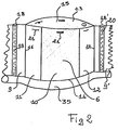
- Figure 1 shows, in summary.perspective perspective, such an assembly intended to form a floating dam.
- Figure 2 is an enlarged view of one of the pockets characteristic of this dam.
- Figures 3 and 4 briefly represent two methods of fixing this dam to the banks of a canal.
- FIG. 5 is a summary representation of an envelope filled with pulverulent absorbent material.
- These connecting strips (9-9 ') have a vertical sheath (18-18') intended to receive the vertical stiffening element (19-20), formed for example by a slat in wood or a tube plugged at its ends.
- each pocket (5-8) comprises closing means and means for anchoring the envelope (25) of absorbent material (26), such as for example snaps (21), adhesive strips to hooks ( 22 ) Velcro type, eyelets or buttons.
- absorbent material such as for example snaps (21), adhesive strips to hooks ( 22 ) Velcro type, eyelets or buttons.
- the absorbent material is in the form of a bag or a porous envelope (25), for example in a light non-woven veil of synthetic fibers.
- This envelope (25) which has the shape of a closed container at its two ends (27-28), contains the absorbent material (26).
- this absorbent material is in powder form. Any material known for its absorbent properties can be used, such as, for example, polyamide pulps, polyurethane foam powders or ground epoxy resin foam powders, as described in French patent application No. 80/06. 538 filed March 20, 1980.
- the ends of the assembly (1) forming a dam are bordered by vertical flaps (30) and (31) also sealed against waste, advantageously made of a coated fabric resistant to hydrocarbons.
- These flaps (30) and (31) may or may not be stiffened by horizontal (32) or vertical (33) slats.
- These flaps (30-31) are articulated along the vertical connection line (50-51) with the assembly (1) and are intended to seal the assembly by resting on the banks or on the banks ( 40) of the channel to be treated.
- these flaps thus ensure the obligatory passage of polluted water over the openworked parts of the elementary pockets and consequently over the envelopes (25) containing the material.
- the bottom (14) of the assembly (1) comprises a horizontal tubular sheath (35), intended to receive a horizontal mooring cable bearing on each bank (40) and more precisely on the mooring members (42) , (43). If necessary, a second mooring cable parallel to it can be placed on the top of the assembly.
- envelopes (25) are filled with an absorbent material (26).
- a vertical mooring member (42) On the banks or on the banks (40) (FIG. 3) of a channel (41) to be treated, a vertical mooring member (42) is pushed in or fixed by any known means. If this is possible, one can also be content to push (see Figure 4) a vertical pile (43) in the bed (44).
- rings (45,46) are slid intended to hang the mooring cable (47) which crosses the bed and is threaded in the horizontal sleeve (35) .
- the two lateral vertical sleeves (2-3) are then threaded onto the vertical piles or similar (42).
- the bags (25) filled with virgin absorbent material (26) are placed in the open elementary pockets (6-8) which are then closed (21-22).
- the bags (25) loaded with polluted particles are changed according to a determined cycle or, if necessary, after an accidental discharge.
- this type of dam can be advantageously used to combat pollution in rivers, in canals, such as for example in industrial and effluent effluents. They can advantageously be placed in the inlet channel of a rainwater treatment plant or at the outlet of a wastewater discharge.
Abstract
Description
L'invention concerne un nouveau type de barrage souple filtrant anti-pollution destiné à retenir et à absorber des déchets répandus à la surface de l'eau ou en suspension dans celle-ci, tels que notamment des hydrocarbures, des graisses, des solvants ou autres produits chimiques.The invention relates to a new type of flexible anti-pollution filtering dam intended to retain and absorb waste spread on the surface of the water or suspended in it, such as in particular hydrocarbons, greases, solvents or other chemicals.
La pollution par hydrocarbures est malheureusement bien connue. Dans le brevet américain US-A-3 702 657, on a décrit un barrage rigide,essentiellement formé par une armature rigide définissant une pluralité d'enceintes contenant une matière absorbante, chaque enceinte étant recouverte d'une grille ajourée. Du fait de sa rigidité, cet ensemble coûteux ne convient que pour de grandes étendues d'eau et non pour l'épuration de canaux de petites dimensions, tels que par exemple les canaux d'effluents d'eaux usées. En outre, dans cette solution, il est indispensable que la matière absorbante remplisse parfaitement les enceintes élémentaires, sinon les hydrocarbures seront mal retenus . Enfin, par suite de sa rigidité, l'ensemble est difficile à monter, à transporter et à stocker, de sorte qu'il est pratiquement destiné à rester sur place. L'invention pallie ces inconvénients. Elle concerne un nouveau type de barrage souple flottant anti-pollution qui soit facile et économique à transporter, à stocker, à monter et à mettre en oeuvre, donne d'excellents résultats sur le plan de la récupération des déchets, notamment dans les canaux de petites dimensions, et enfin soit auto-flottant afin de suivre les variations de niveau.Oil pollution is unfortunately well known. In US patent US-A-3,702,657, a rigid barrier has been described, essentially formed by a rigid frame defining a plurality of enclosures containing an absorbent material, each enclosure being covered with an openwork grid. Due to its rigidity, this expensive assembly is only suitable for large bodies of water and not for the purification of small canals, such as for example wastewater effluent channels. In addition, in this solution, it is essential that the absorbent material perfectly fill the elementary enclosures, otherwise the hydrocarbons will be poorly retained. Finally, due to its rigidity, the assembly is difficult to assemble, transport and store, so that it is practically intended to remain in place. The invention overcomes these drawbacks. It relates to a new type of flexible floating anti-pollution boom which is easy and economical to transport, store, assemble and operate, gives excellent results in terms of waste recovery, in particular in the canals of small dimensions, and finally be self-floating in order to follow variations in level.
Ca barrage anti-pollution destiné à retenir et à absorber des déchets, tels que notamment des hydrocarbures, répandus à la surface de l'eau ou en suspension dans celle-ci, du type comprenant essentiellement :
- - une pluralité de poches ajourées, juxtaposées côte à côte, ouvertes sur le haut, mais fermées sur le bas, destinées à recevoir le matériau absorbant placé dans une enveloppe poreuse ;
- - des moyens pour amarrer l'ensemble verticalement et horizontalement aux berges du canal à épurer ;
- - des moyens de rigidification de l'ensemble, se caractérise :
- - en ce que les moyens de.rigidification sont placés verticalement entre deux poches souples successives,
- - et en ce que la face avant ajourée de chaque poche élémentaire est bordée de chaque côté par une bande verticale étanche aux déchets à retenir.
- - les poches sont formées dans une étoffe ajourée, tissée ou non, dont le réseau de la maille de la face avant est moins serré que le réseau de la face arrière ;
- - la partie supérieure ouverte de chaque poche présente des moyens destines à fermer celle-ci et à attacher dans celle-ci l'enveloppe poreuse contenant le matériau absorbant ;
- - les bords étanches de deux poches contigùes sont reliés entre eux par une portion verticale également étanche, dans laquelle est placé ledit moyen de rigidification vertical ;
- - les bandes étanches et les parties ajourées sont en tissu enduit ;
- - les moyens d'amarrage de l'ensemble sont constitués par :
- . deux fourreaux verticaux placés à chaque extrémité de l'ensemble, destinés à s'emmancher sur un organe vertical fixé aux berges ou dans le lit du canal,
- . et par un câble horizontal passant dans au moins un fourreau horizontal prévu à cet effet sous l'ensemble ;
- - l'ensemble présente à chaque extrémité latérale un élément vertical étanche, mobile sur l'axe vertical de liaison avec l'ensemble, destiné à s'appuyer sur les berges, afin d'assurer l'étanchéité de l'ensemble ;
- - la matière absorbante se présente sous forme de poudre et est placée dans une enveloppe poreuse formant coussin.
- - A plurality of perforated pockets, juxtaposed side by side, open at the top, but closed at the bottom, intended to receive the absorbent material placed in a porous envelope;
- - Means for mooring the assembly vertically and horizontally to the banks of the channel to be purified;
- - means for stiffening the assembly, is characterized:
- - in that the de.rigidification means are placed vertically between two successive flexible pockets,
- - And in that the perforated front face of each elementary pocket is bordered on each side by a vertical strip sealed against the waste to be retained.
- - The pockets are formed in an openwork fabric, woven or not, the network of the mesh of the front face is less tight than the network of the rear face;
- - The open upper part of each pocket has means intended to close the latter and to attach therein the porous envelope containing the material absorbent;
- - The sealed edges of two contiguous pockets are interconnected by a vertical portion also sealed, in which is placed said vertical stiffening means;
- - the waterproof bands and the openwork parts are in coated fabric;
- - the mooring means of the assembly consist of:
- . two vertical sleeves placed at each end of the assembly, intended to be fitted onto a vertical member fixed to the banks or in the channel bed,
- . and by a horizontal cable passing through at least one horizontal sleeve provided for this purpose under the assembly;
- - The assembly has at each lateral end a sealed vertical element, movable on the vertical axis of connection with the assembly, intended to rest on the banks, in order to ensure the sealing of the assembly;
- - the absorbent material is in powder form and is placed in a porous envelope forming a cushion.
La manière dont l'invention peut être réalisée et les avantages qui en découlent ressortiront mieux des exemples de réalisation qui suivent donnés à titre indicatif et non limitatif, à l'appui des figures annexées.The manner in which the invention can be implemented and the advantages which result therefrom will emerge more clearly from the examples of embodiment which follow, given by way of non-limiting example, in support of the appended figures.
La figure 1 représente,en vue.perspective sommaire, un tel ensemble destiné à former barrage flottant.Figure 1 shows, in summary.perspective perspective, such an assembly intended to form a floating dam.
La figure 2 est une vue grossie d'une des poches caractéristique de ce barrage.Figure 2 is an enlarged view of one of the pockets characteristic of this dam.
Les figures 3 et 4 représentent sommairement deux modes de fixation de ce barrage aux berges d'un canal.Figures 3 and 4 briefly represent two methods of fixing this dam to the banks of a canal.
La figure 5 est une représentation sommaire d'une enveloppe garnie de matière absorbante pulvérulente.FIG. 5 is a summary representation of an envelope filled with pulverulent absorbent material.
En se référant aux figures, le barrage anti-pollution flottant se compose d'un ensemble vertical (1) souple comprenant à chaque extrémité un fourreau tubulaire vertical d'amarrage (2) et (3),
par exemple en tissu-enduit souple,
soudé ou cousu, à un complexe vertical (4) formé par une pluralité de poches successives juxtaposées ajourées (5-6-7 et 8). Ces poches élémentaires sont séparées entre elles par des portions verticales (9) étanches aux déchets à retenir, par exemple en tissu, notamment enduit ou en un film de matière synthétique souple. Ces poches (6-8) (voir figure 2) se composent essentiellement :
- - sur l'avant, d'une étoffe, tissée ou non, ajourée (10), bordée des deux côtés par une bande verticale (11) et (12) en un tissu enduit étanche aux déchets ou en un matériau similaire à (9) ;
- - sur l'arrière, d'une autre étoffe (13), tissée ou non,.analogue et parallèle à (10), dont soit la maille du réseau est plus fine que celle de la face avant ou dont la surface est plus grande que celle de la face avant.;
- - ces deux étoffes avant et arrière (10-13) sont soudées ou cousues sur le bas sur la ligne (14).
for example in flexible coated fabric,
welded or sewn, to a vertical complex (4) formed by a plurality of successive juxtaposed openwork pockets (5-6-7 and 8). These elementary pockets are separated from each other by vertical portions (9) which are impermeable to the waste to be retained, for example in fabric, in particular coated or in a film of flexible synthetic material. These pockets (6-8) (see Figure 2) essentially consist of:
- - on the front, of a fabric, woven or not, perforated (10), bordered on both sides by a vertical strip (11) and (12) in a coated fabric impervious to waste or in a material similar to (9 );
- - on the back, of another fabric (13), woven or not, analogous and parallel to (10), whose mesh of the network is finer than that of the front face or whose surface is larger than that of the front face .;
- - these two front and rear fabrics (10-13) are welded or sewn on the bottom on the line (14).
La poche élémentaire (6) ainsi formée, fermée sur le bas (14), mais ouverte sur le haut en (15), est soudée par ses côtés (16-17) aux bandes de liaison (9-9'). Ces bandes de liaison (9-9') présentent un fourreau vertical (18-18') destiné à recevoir l'élément vertical de rigidification (19-20), formé par exemple par une latte en bois ou un tube bouché à ses extrémités.The elementary pocket (6) thus formed, closed at the bottom (14), but open at the top at (15), is welded by its sides (16-17) to the connecting strips (9-9 '). These connecting strips (9-9 ') have a vertical sheath (18-18') intended to receive the vertical stiffening element (19-20), formed for example by a slat in wood or a tube plugged at its ends.
Le haut de chaque poche (5-8) comporte des moyens de fermeture et des moyens d'ancrage de l'enveloppe (25) de matière absorbante (26), telles que par exemple des boutons pressions (21), des bandes adhésives à crochets (22) type Velcro, des oeillettons ou des boutons.The top of each pocket (5-8) comprises closing means and means for anchoring the envelope (25) of absorbent material (26), such as for example snaps (21), adhesive strips to hooks ( 22 ) Velcro type, eyelets or buttons.
La matière absorbante se présente sous la forme d'un sac ou d'une enveloppe poreuse (25), par exemple en un voile non tissé léger en fibres synthétiques. Cette enveloppe (25) qui a la forme d'un berlingot fermé à ses deux extrémités (27-28), contient la matière absorbante (26). Avantageusement, cette matière absorbante se présente sous forme pulvérulente. On peut utiliser toute matière connue pour ses propriétés absorbantes, telles que par exemple des pulpes de polyamide, des poudres de mousse de polyuréthane ou des poudres de mousse de résine epoxy broyée,tel que décrit dans la demande de brevet français n° 80/06 538 déposé le 20 Mars 1980.The absorbent material is in the form of a bag or a porous envelope (25), for example in a light non-woven veil of synthetic fibers. This envelope (25) which has the shape of a closed container at its two ends (27-28), contains the absorbent material (26). Advantageously, this absorbent material is in powder form. Any material known for its absorbent properties can be used, such as, for example, polyamide pulps, polyurethane foam powders or ground epoxy resin foam powders, as described in French patent application No. 80/06. 538 filed March 20, 1980.
Les extrémités de l'ensemble (1) formant barrage sont bordées par des bavettes verticales (30) et (31) également étanches aux déchets, réalisées avantageusement en un tissu enduit résistant aux hydrocarbures. Ces bavettes (30) et (31) peuvent être ou non rigidifiées par des lattes horizontales (32) ou verticales (33). Ces bavettes (30-31) sont articulées suivant la ligne de liaison verticale (50-51) avec l'ensemble (1) et sont destinées à assurer l'étanchéité de l'ensemble en prenant appui sur les rives ou sur les berges (40) du canal à traiter. En outre, ces bavettes assurent ainsi le passage obligatoire de l'eau polluée sur les parties - ajourées des poches élémentaires et par voie de conséquence sur les enveloppes (25) contenant le matériauThe ends of the assembly (1) forming a dam are bordered by vertical flaps (30) and (31) also sealed against waste, advantageously made of a coated fabric resistant to hydrocarbons. These flaps (30) and (31) may or may not be stiffened by horizontal (32) or vertical (33) slats. These flaps (30-31) are articulated along the vertical connection line (50-51) with the assembly (1) and are intended to seal the assembly by resting on the banks or on the banks ( 40) of the channel to be treated. In addition, these flaps thus ensure the obligatory passage of polluted water over the openworked parts of the elementary pockets and consequently over the envelopes (25) containing the material.
absorbant (26). De la sorte, le flux du courant à épurer est bien concentré sur le tissu ajouré (10) et,par là sur tout le volume du coussin (25), même si celui-ci ne remplit pas complètement la poche élémentaire (6).absorbent (26). In this way, the flow of the current to be purified is well concentrated on the openwork fabric (10) and, thereby, over the entire volume of the cushion (25), even if the latter does not completely fill the elementary pocket (6).
Le bas (14) de l'ensemble (1) comporte un fourreau tubulaire horizontal (35), destiné à recevoir un câble d'amarrage horizontal prenant appui sur chaque berge (40) et plus précisément sur lés organes d'amarrage (42), (43). Si nécessaire, un second câble d'amarrage parallèle à celui-ci peut être placé sur le haut de l'ensemble.The bottom (14) of the assembly (1) comprises a horizontal tubular sheath (35), intended to receive a horizontal mooring cable bearing on each bank (40) and more precisely on the mooring members (42) , (43). If necessary, a second mooring cable parallel to it can be placed on the top of the assembly.
La mise en place de l'ensemble s'effectue de la manière suivante. Séparément, on remplit des enveloppes (25) d'une matière absorbante (26).The assembly of the assembly is carried out as follows. Separately, envelopes (25) are filled with an absorbent material (26).
Sur les rives ou sur les berges (40) (figure 3) d'un canal (41) à traiter, on enfonce ou on fixe par tout moyen connu, un organe d'amarrage vertical (42). Si la chose est possible, on peut aussi se contenter d'enfoncer (voir figure 4) un pieux vertical (43) dans le lit (44). Sur ces éléments d'amarrage (42-43-43'), on fait coulisser des anneaux (45,46) destinés à accrocher le câble d'amarrage (47) qui traverse le lit et est enfilé dans le fourreau horizontal (35). On enfile ensuite les deux fourreaux verticaux latéraux (2-3) sur les pieux (43) verticaux ou analogues (42).On the banks or on the banks (40) (FIG. 3) of a channel (41) to be treated, a vertical mooring member (42) is pushed in or fixed by any known means. If this is possible, one can also be content to push (see Figure 4) a vertical pile (43) in the bed (44). On these mooring elements (42-43-43 '), rings (45,46) are slid intended to hang the mooring cable (47) which crosses the bed and is threaded in the horizontal sleeve (35) . The two lateral vertical sleeves (2-3) are then threaded onto the vertical piles or similar (42).
Sous l'effet du courant, les bavettes d'extrémité (30) et (31) sont plaquées contre les berges (40).Under the effect of the current, the end flaps (30) and (31) are pressed against the banks (40).
Par un moyen quelconque (barque.ou à pied), on pose les sacs (25) remplis de matière absorbante vierge (26) dans les poches élémentaires (6-8) ouvertes que l'on ferme ensuite (21-22).By any means (boat or on foot), the bags (25) filled with virgin absorbent material (26) are placed in the open elementary pockets (6-8) which are then closed (21-22).
. Grâce aux bandes verticales étanches (9-11-12) et aux bavettes latérales étanches (30-31), les pollutions sont canalisées sur les portions poreuses (10), donc sur la matière absorbante (26) contenue dans l'enveloppe (25).. Thanks to the waterproof vertical strips (9-11-12) and the waterproof side flaps (30-31), pollution are channeled on the porous portions (10), therefore on the absorbent material (26) contained in the envelope (25).
Si d'aventure le niveau d'eau varie, du fait de la den - sité des sacs (25), l'ensemble peut coulisser le long des pieux (42-43) grâce aux anneaux (45-46). Cet ensemble est donc auto-flottant.If by chance the water level varies, due to the density of the bags (25), the assembly can slide along the piles (42-43) thanks to the rings (45-46). This set is therefore self-floating.
On change les sacs (25) chargés de particules polluées selon un cycle déterminé ou s'il y a lieu, après une décharge accidentelle.The bags (25) loaded with polluted particles are changed according to a determined cycle or, if necessary, after an accidental discharge.
Le barrage selon l'invention présente de nombreux avantages par rapport aux barrages anti-pollution proposés à ce jour. On peut citer :
- - du fait de la souplesse générale, la possibilité d'être replié ou roulé sur lui-même, donc facilité de transport, de stockage et de montage ;
- - la facilité d'exploitation,qui nécessite peu de personnel ;
- - la possibilité de réaliser des barrages statiques, souples et à prix réduit ;
- - la facilité de manipulation de l'élément absorbant qui se trouve dans des cartouches faciles à changer et à stocker ;
- - la possibilité de réaliser des barrages auto- flottants, ce qui permet de suivre les variations du niveau de l'eau ;
- - la possibilité de réaliser simultanément barrage et l'absorption, notamment pour les risées d'hydrocarbures.
- - because of the general flexibility, the possibility of being folded or rolled up on itself, therefore ease of transport, storage and assembly;
- - ease of operation, which requires few staff;
- - the possibility of making static, flexible dams at a reduced price;
- - the ease of handling of the absorbent element which is in cartridges which are easy to change and to store;
- - the possibility of making self-floating dams, which makes it possible to monitor variations in the water level;
- - the possibility of simultaneously carrying out a dam and absorption, in particular for hydrocarbon risées.
De la sorte, ce type de barrage peut être utilisé avantageusement pour lutter contre la pollution dans des rivières, dans des canaux, tels que par exemple dans les effluents d'eaux industrielles, d'eaux usées. On peut avantageusement les placer dans le canal d'entrée d'une station d'épuration d'eaux pluviales ou à la sortie d'un rejet d'eaux usées.In this way, this type of dam can be advantageously used to combat pollution in rivers, in canals, such as for example in industrial and effluent effluents. They can advantageously be placed in the inlet channel of a rainwater treatment plant or at the outlet of a wastewater discharge.
Claims (7)
Applications Claiming Priority (2)
| Application Number | Priority Date | Filing Date | Title |
|---|---|---|---|
| FR8218373A FR2535362A1 (en) | 1982-10-28 | 1982-10-28 | ANTI-POLLUTION FILTERING FLOATING DAM |
| FR8218373 | 1982-10-28 |
Publications (2)
| Publication Number | Publication Date |
|---|---|
| EP0108024A1 true EP0108024A1 (en) | 1984-05-09 |
| EP0108024B1 EP0108024B1 (en) | 1985-12-27 |
Family
ID=9278844
Family Applications (1)
| Application Number | Title | Priority Date | Filing Date |
|---|---|---|---|
| EP83420163A Expired EP0108024B1 (en) | 1982-10-28 | 1983-10-13 | Floating and filtering anti-pollution barrier |
Country Status (4)
| Country | Link |
|---|---|
| EP (1) | EP0108024B1 (en) |
| DE (1) | DE3361646D1 (en) |
| FR (1) | FR2535362A1 (en) |
| OA (1) | OA07573A (en) |
Cited By (5)
| Publication number | Priority date | Publication date | Assignee | Title |
|---|---|---|---|---|
| EP0325528A1 (en) * | 1988-01-18 | 1989-07-26 | Caoutchouc Manufacture Et Plastiques | Device for joining plates or manufacturing pipes and their applications |
| AU621157B2 (en) * | 1988-10-27 | 1992-03-05 | Norva Invest A/S | Oil collector |
| EP0618883A1 (en) * | 1991-10-08 | 1994-10-12 | HILL, Alan, R. | Oil absorption method and apparatus utilizing a replaceable bladder |
| US7054648B2 (en) | 2001-10-22 | 2006-05-30 | Telefonaktiebolaget Lm Ericsson (Publ) | Location privacy proxy server and method in a telecommunication network |
| WO2020064735A1 (en) * | 2018-09-25 | 2020-04-02 | Zachert Wolfgang | Keratin-containing bag and use thereof |
Citations (4)
| Publication number | Priority date | Publication date | Assignee | Title |
|---|---|---|---|---|
| FR2101764A5 (en) * | 1970-07-16 | 1972-03-31 | Johns Manville | |
| US3702657A (en) * | 1971-02-11 | 1972-11-14 | Exxon Production Research Co | Pollution containment barrier |
| FR2163836A5 (en) * | 1971-12-03 | 1973-07-27 | Rebut Paul | Oil slick collector - from tubular woven elements |
| US4111813A (en) * | 1976-10-05 | 1978-09-05 | Paul Preus | Hydrocarbon containment and control systems |
-
1982
- 1982-10-28 FR FR8218373A patent/FR2535362A1/en active Granted
-
1983
- 1983-10-13 EP EP83420163A patent/EP0108024B1/en not_active Expired
- 1983-10-13 DE DE8383420163T patent/DE3361646D1/en not_active Expired
- 1983-10-26 OA OA58144A patent/OA07573A/en unknown
Patent Citations (4)
| Publication number | Priority date | Publication date | Assignee | Title |
|---|---|---|---|---|
| FR2101764A5 (en) * | 1970-07-16 | 1972-03-31 | Johns Manville | |
| US3702657A (en) * | 1971-02-11 | 1972-11-14 | Exxon Production Research Co | Pollution containment barrier |
| FR2163836A5 (en) * | 1971-12-03 | 1973-07-27 | Rebut Paul | Oil slick collector - from tubular woven elements |
| US4111813A (en) * | 1976-10-05 | 1978-09-05 | Paul Preus | Hydrocarbon containment and control systems |
Cited By (6)
| Publication number | Priority date | Publication date | Assignee | Title |
|---|---|---|---|---|
| EP0325528A1 (en) * | 1988-01-18 | 1989-07-26 | Caoutchouc Manufacture Et Plastiques | Device for joining plates or manufacturing pipes and their applications |
| AU621157B2 (en) * | 1988-10-27 | 1992-03-05 | Norva Invest A/S | Oil collector |
| EP0618883A1 (en) * | 1991-10-08 | 1994-10-12 | HILL, Alan, R. | Oil absorption method and apparatus utilizing a replaceable bladder |
| EP0618883A4 (en) * | 1991-10-08 | 1994-11-23 | Alan R Hill | Oil absorption method and apparatus utilizing a replaceable bladder. |
| US7054648B2 (en) | 2001-10-22 | 2006-05-30 | Telefonaktiebolaget Lm Ericsson (Publ) | Location privacy proxy server and method in a telecommunication network |
| WO2020064735A1 (en) * | 2018-09-25 | 2020-04-02 | Zachert Wolfgang | Keratin-containing bag and use thereof |
Also Published As
| Publication number | Publication date |
|---|---|
| FR2535362A1 (en) | 1984-05-04 |
| OA07573A (en) | 1985-03-31 |
| FR2535362B1 (en) | 1985-03-08 |
| EP0108024B1 (en) | 1985-12-27 |
| DE3361646D1 (en) | 1986-02-06 |
Similar Documents
| Publication | Publication Date | Title |
|---|---|---|
| CN101761060B (en) | Water area dirt-removing interception and absorption dam and assembly component thereof | |
| FR2465510A1 (en) | FILTER FOR EXCREMENT COLLECTOR DEVICE | |
| EP0108024B1 (en) | Floating and filtering anti-pollution barrier | |
| FR2657370A1 (en) | METHOD AND ELEMENT FOR PRODUCING STRUCTURES FOR CONTAINING SOIL SURFACES | |
| EP0500723A1 (en) | Floating barrage. | |
| EP1570131B1 (en) | Device for collecting items floating at the surface of the sea | |
| US5348661A (en) | Oil absorption method and apparatus utilizing a replaceable bladder | |
| FR2552133A1 (en) | Modular barrage filtering out water pollution | |
| JPH1077622A (en) | Flood control sack body | |
| FR2719785A1 (en) | Bag for handling biological samples including filter | |
| WO2001021274A1 (en) | Improvements to filters with granular material bed, in particular for water treatment | |
| BE1004523A3 (en) | Device air cleaner. | |
| EP0481840A1 (en) | Helicopter landing pad | |
| EP0402243B1 (en) | Filtering device particularly for the purification of swimming pool water | |
| FR2783006A1 (en) | MIXED ISOTHERMAL AND SAFETY ROLL-UP COVER FOR POOLS | |
| CA2495976C (en) | Fluid flow control barrier | |
| JP2017007613A (en) | Cover sheet-like object and sheet structure used for motor-truck loading space | |
| WO2015189355A1 (en) | Device for retaining solids, methods for manufacturing and for attaching such a device | |
| LU82819A1 (en) | ACTIVE FLOATING DAM USED FOR DEPOLLUTION | |
| GB2337690A (en) | Absorbing pollutants from surfaces | |
| CH677242A5 (en) | Barrier grid for polluted waterway - has mesh between upper and lower cables, top floats and side fittings for end to end connection | |
| KR101130918B1 (en) | A water treatment system by non-efflux self-weight water pressure filteration using elvan | |
| WO1993007090A1 (en) | Oil absorption method and apparatus utilizing a replaceable bladder | |
| EP2868821B1 (en) | Gully with filter device | |
| DE10044014C2 (en) | Algae filter system Cleaning the beach of algae and suspended matter in the wet area |
Legal Events
| Date | Code | Title | Description |
|---|---|---|---|
| PUAI | Public reference made under article 153(3) epc to a published international application that has entered the european phase |
Free format text: ORIGINAL CODE: 0009012 |
|
| AK | Designated contracting states |
Designated state(s): BE DE IT NL |
|
| 17P | Request for examination filed |
Effective date: 19840524 |
|
| GRAA | (expected) grant |
Free format text: ORIGINAL CODE: 0009210 |
|
| AK | Designated contracting states |
Designated state(s): BE DE IT NL |
|
| PG25 | Lapsed in a contracting state [announced via postgrant information from national office to epo] |
Ref country code: NL Effective date: 19851227 Ref country code: IT Free format text: LAPSE BECAUSE OF FAILURE TO SUBMIT A TRANSLATION OF THE DESCRIPTION OR TO PAY THE FEE WITHIN THE PRESCRIBED TIME-LIMIT;WARNING: LAPSES OF ITALIAN PATENTS WITH EFFECTIVE DATE BEFORE 2007 MAY HAVE OCCURRED AT ANY TIME BEFORE 2007. THE CORRECT EFFECTIVE DATE MAY BE DIFFERENT FROM THE ONE RECORDED. Effective date: 19851227 |
|
| REF | Corresponds to: |
Ref document number: 3361646 Country of ref document: DE Date of ref document: 19860206 |
|
| NLV1 | Nl: lapsed or annulled due to failure to fulfill the requirements of art. 29p and 29m of the patents act | ||
| PLBE | No opposition filed within time limit |
Free format text: ORIGINAL CODE: 0009261 |
|
| STAA | Information on the status of an ep patent application or granted ep patent |
Free format text: STATUS: NO OPPOSITION FILED WITHIN TIME LIMIT |
|
| 26N | No opposition filed | ||
| PG25 | Lapsed in a contracting state [announced via postgrant information from national office to epo] |
Ref country code: BE Effective date: 19871031 |
|
| BERE | Be: lapsed |
Owner name: BAT TARAFLEX Effective date: 19871031 |
|
| PG25 | Lapsed in a contracting state [announced via postgrant information from national office to epo] |
Ref country code: DE Effective date: 19880701 |