EP0108024B1 - Floating and filtering anti-pollution barrier - Google Patents
Floating and filtering anti-pollution barrier Download PDFInfo
- Publication number
- EP0108024B1 EP0108024B1 EP83420163A EP83420163A EP0108024B1 EP 0108024 B1 EP0108024 B1 EP 0108024B1 EP 83420163 A EP83420163 A EP 83420163A EP 83420163 A EP83420163 A EP 83420163A EP 0108024 B1 EP0108024 B1 EP 0108024B1
- Authority
- EP
- European Patent Office
- Prior art keywords
- vertical
- perforated
- barrier according
- banks
- assembly
- Prior art date
- Legal status (The legal status is an assumption and is not a legal conclusion. Google has not performed a legal analysis and makes no representation as to the accuracy of the status listed.)
- Expired
Links
- 230000004888 barrier function Effects 0.000 title claims description 10
- 238000007667 floating Methods 0.000 title claims description 8
- 238000001914 filtration Methods 0.000 title claims description 3
- 239000004744 fabric Substances 0.000 claims description 11
- 239000002699 waste material Substances 0.000 claims description 9
- XLYOFNOQVPJJNP-UHFFFAOYSA-N water Substances O XLYOFNOQVPJJNP-UHFFFAOYSA-N 0.000 claims description 7
- 229930195733 hydrocarbon Natural products 0.000 claims description 6
- 150000002430 hydrocarbons Chemical class 0.000 claims description 6
- 239000000843 powder Substances 0.000 claims description 5
- 239000011358 absorbing material Substances 0.000 claims 3
- 229920003002 synthetic resin Polymers 0.000 claims 1
- 239000000057 synthetic resin Substances 0.000 claims 1
- 230000002745 absorbent Effects 0.000 description 17
- 239000002250 absorbent Substances 0.000 description 17
- 239000000463 material Substances 0.000 description 17
- 230000000717 retained effect Effects 0.000 description 3
- 239000002351 wastewater Substances 0.000 description 3
- 238000010521 absorption reaction Methods 0.000 description 2
- 229920002994 synthetic fiber Polymers 0.000 description 2
- 210000001519 tissue Anatomy 0.000 description 2
- 239000004215 Carbon black (E152) Substances 0.000 description 1
- 239000004952 Polyamide Substances 0.000 description 1
- 229920005830 Polyurethane Foam Polymers 0.000 description 1
- 239000000853 adhesive Substances 0.000 description 1
- 230000001070 adhesive effect Effects 0.000 description 1
- 238000004873 anchoring Methods 0.000 description 1
- 230000000694 effects Effects 0.000 description 1
- 239000003822 epoxy resin Substances 0.000 description 1
- 239000006260 foam Substances 0.000 description 1
- 239000008235 industrial water Substances 0.000 description 1
- 230000000670 limiting effect Effects 0.000 description 1
- 238000000034 method Methods 0.000 description 1
- 239000002245 particle Substances 0.000 description 1
- 229920002647 polyamide Polymers 0.000 description 1
- 229920000647 polyepoxide Polymers 0.000 description 1
- 239000011496 polyurethane foam Substances 0.000 description 1
- 238000000746 purification Methods 0.000 description 1
- 238000011084 recovery Methods 0.000 description 1
- 230000002829 reductive effect Effects 0.000 description 1
- 230000002787 reinforcement Effects 0.000 description 1
- 230000000284 resting effect Effects 0.000 description 1
- 238000007789 sealing Methods 0.000 description 1
- 239000002904 solvent Substances 0.000 description 1
- 230000003068 static effect Effects 0.000 description 1
- 239000000126 substance Substances 0.000 description 1
- 239000012209 synthetic fiber Substances 0.000 description 1
Images

Classifications
-
- E—FIXED CONSTRUCTIONS
- E02—HYDRAULIC ENGINEERING; FOUNDATIONS; SOIL SHIFTING
- E02B—HYDRAULIC ENGINEERING
- E02B15/00—Cleaning or keeping clear the surface of open water; Apparatus therefor
- E02B15/04—Devices for cleaning or keeping clear the surface of open water from oil or like floating materials by separating or removing these materials
- E02B15/06—Barriers therefor construed for applying processing agents or for collecting pollutants, e.g. absorbent
-
- Y—GENERAL TAGGING OF NEW TECHNOLOGICAL DEVELOPMENTS; GENERAL TAGGING OF CROSS-SECTIONAL TECHNOLOGIES SPANNING OVER SEVERAL SECTIONS OF THE IPC; TECHNICAL SUBJECTS COVERED BY FORMER USPC CROSS-REFERENCE ART COLLECTIONS [XRACs] AND DIGESTS
- Y02—TECHNOLOGIES OR APPLICATIONS FOR MITIGATION OR ADAPTATION AGAINST CLIMATE CHANGE
- Y02A—TECHNOLOGIES FOR ADAPTATION TO CLIMATE CHANGE
- Y02A20/00—Water conservation; Efficient water supply; Efficient water use
- Y02A20/20—Controlling water pollution; Waste water treatment
- Y02A20/204—Keeping clear the surface of open water from oil spills
Definitions
- the invention relates to a new type of flexible anti-pollution filtering dam intended to retain and absorb waste spread on the surface of the water or suspended in it, such as in particular hydrocarbons, greases, solvents or other chemicals.
- the invention overcomes these drawbacks. It relates to a new type of flexible floating anti-pollution boom which is easy and economical to transport, store, assemble and operate, gives excellent results in terms of waste recovery, in particular in the canals of small dimensions, and finally be self-floating in order to follow variations in level.
- the assembly is therefore easy to fold, transport, store or assemble and can easily marry very varied profiles.
- the perforated front face is advantageously smaller than the rear perforated face, so that all of the current flow is concentrated on the absorbent material contained in the envelope, even if this envelope does not exactly fill the entire volume of the elementary pocket.
- link (9-9 ') have a vertical sheath (18-18') intended to receive the vertical stiffening element (19-20), formed for example by a wooden slat or a tube plugged at its ends.
- each pocket (5-8) comprises closing means and means for anchoring the envelope (25) (FIG. 5) of absorbent material (26), such as for example snaps (21), adhesive hooks (22) such as Velcro (registered trademark), eyelets or buttons.
- absorbent material such as for example snaps (21), adhesive hooks (22) such as Velcro (registered trademark), eyelets or buttons.
- the absorbent material is in the form of a bag or a porous envelope (25), for example in a light non-woven veil of synthetic fibers.
- This envelope (25) which has the shape of a closed container at its two ends (27-28), contains the absorbent material (26).
- this absorbent material is in powder form. Any material known for its absorbent properties can be used, such as, for example, polyamide pulps, polyurethane foam powders or ground epoxy resin foam powders, as described in French patent application no. ° 80/06 538 (FR-A-2 478 667) filed on March 24, 1980.
- the ends of the assembly (1) forming a dam are bordered by vertical flaps (30) and (31) also sealed against waste, advantageously made of a coated fabric resistant to hydrocarbons.
- These flaps (30) and (31) may or may not be stiffened by horizontal (32) or vertical (33) slats.
- These flaps (30-31) are articulated along the vertical connection line (50-51) with the assembly (1) and are intended to seal the assembly by resting on the banks or on the banks ( 40) of the channel to be treated.
- these flaps thus ensure the obligatory passage of polluted water over the perforated parts of the elementary pockets and consequently over the envelopes (25) containing the absorbent material (26). In this way, the flow of current to be purified is well concentrated on the perforated fabric (10) and thereby on the entire volume of the cushion (25), even if the latter does not completely fill the elementary pocket (6).
- the bottom (14) of the assembly (1) comprises a horizontal tubular sheath (35), intended to receive a horizontal mooring cable bearing on each bank (40) and more precisely on the mooring members (42) , (43). If necessary, a second mooring cable parallel to it can be placed on the top of the assembly.
- envelopes (25) are filled with an absorbent material (26).
- a vertical mooring member (42) On the banks or on the banks (40) (FIG. 3) of a channel (41) to be treated, a vertical mooring member (42) is pushed in or fixed by any known means. If this is possible, one can also be content to push (see Figure 4) a vertical pile (43) in the bed (44).
- rings (45, 46) are slid intended to hang the mooring cable (47) which passes through the bed and is threaded in the horizontal sleeve (35) .
- the two lateral vertical sleeves (2-3) are then threaded onto the vertical piles or similar (42).
- the bags (25) filled with virgin absorbent material (26) are placed in the open elementary pockets (6-8) which are then closed (21-22).
- the bags (25) loaded with polluted particles are changed according to a determined cycle or, if necessary, after an accidental discharge.
- this type of dam can be used advantageously to fight against pollution in rivers, in canals, such as for example in the effluents of industrial water, of waste water. They can advantageously be placed in the inlet channel of a rainwater treatment plant or at the outlet of a wastewater discharge.
Landscapes
- Engineering & Computer Science (AREA)
- General Engineering & Computer Science (AREA)
- Environmental & Geological Engineering (AREA)
- Mechanical Engineering (AREA)
- Civil Engineering (AREA)
- Structural Engineering (AREA)
- Solid-Sorbent Or Filter-Aiding Compositions (AREA)
- Removal Of Floating Material (AREA)
Description
L'invention concerne un nouveau type de barrage souple filtrant anti-pollution destiné à retenir et à absorber des déchets répandus à la surface de l'eau ou en suspension dans celle-ci, tels que notamment des hydrocarbures, des graisses, des solvants ou autres produits chimiques.The invention relates to a new type of flexible anti-pollution filtering dam intended to retain and absorb waste spread on the surface of the water or suspended in it, such as in particular hydrocarbons, greases, solvents or other chemicals.
La pollution par hydrocarbures est malheureusement bien connue.Oil pollution is unfortunately well known.
Dans le brevet américain US-A-3 702 657, on a décrit un barrage rigide, essentiellement formé par une armature rigide définissant une pluralité d'enceintes contenant une matière absorbante, chaque enceinte étant recouverte d'une grille ajourée. Du fait de sa rigidité, cet ensemble coûteux ne convient que pour de grandes étendues d'eau et non pour l'épuration de canaux de petites dimensions, tels que par exemple les canaux d'effluents d'eaux usées. En outre, dans cette solution, il est indispensable que la matière absorbante remplisse parfaitement les enceintes élémentaires, sinon les hydrocarbures seront mal retenus. Enfin, par suite de sa rigidité, l'ensemble est difficile à monter, à transporter et à stocker, de sorte qu'il est pratiquement destiné à rester sur place.In US patent US-A-3,702,657, a rigid barrier has been described, essentially formed by a rigid reinforcement defining a plurality of enclosures containing an absorbent material, each enclosure being covered with a perforated grid. Due to its rigidity, this expensive assembly is only suitable for large bodies of water and not for the purification of small canals, such as for example wastewater effluent channels. In addition, in this solution, it is essential that the absorbent material perfectly fill the elementary enclosures, otherwise the hydrocarbons will be poorly retained. Finally, due to its rigidity, the assembly is difficult to assemble, transport and store, so that it is practically intended to remain in place.
L'invention pallie ces inconvénients. Elle concerne un nouveau type de barrage souple flottant anti-pollution qui soit facile et économique à transporter, à stocker, à monter et à mettre en oeuvre, donne d'excellents résultats sur le plan de la récupération des déchets, notamment dans les canaux de petites dimensions, et enfin soit auto-flottant afin de suivre les variations de niveau.The invention overcomes these drawbacks. It relates to a new type of flexible floating anti-pollution boom which is easy and economical to transport, store, assemble and operate, gives excellent results in terms of waste recovery, in particular in the canals of small dimensions, and finally be self-floating in order to follow variations in level.
Ce barrage anti-pollution destiné à retenir et à absorber des déchets, tels que notamment des hydrocarbures, répandus à la surface de l'eau ou en suspension dans celle-ci, du type comprenant:
- - une pluralité de poches ajourées, juxtaposées côte à côte, ouvertes sur le haut, destinées à recevoir le matériau absorbant placé dans des enveloppes poreuses;
- - des moyens pour amarrer l'ensemble verticalement et horizontalement aux berges du canal à épurer;
- - des moyens de rigidification de l'ensemble, se caractérise:
- - en ce que les moyens de rigidification sont placés verticalement entre deux poches souples successives,
- - et en ce que la face avant ajourée de chaque poche souple élémentaire est bordée de chaque côté par une bande verticale étanche aux déchets à retenir.
- - A plurality of perforated pockets, juxtaposed side by side, open at the top, intended to receive the absorbent material placed in porous envelopes;
- - Means for mooring the assembly vertically and horizontally to the banks of the channel to be purified;
- - means for stiffening the assembly, is characterized:
- - in that the stiffening means are placed vertically between two successive flexible pockets,
- - And in that the perforated front face of each elementary flexible pocket is bordered on each side by a vertical strip sealed against the waste to be retained.
Ainsi, comme la rigidification de l'ensemble n'est réalisée qu'entre deux poches souples successives, l'ensemble est donc facile à replier, à transporter, à stocker ou à monter et peut facilement épouser des profils très variés. Par ailleurs, la face avant ajourée est avantaqeusement plus petite que la face ajourée arrière, de sorte qu'on concentre tout le flux du courant sur la matière absorbante contenue dans l'enveloppe, même si cette enveloppe ne remplit pas exactement tout le volume de la poche élémentaire.Thus, as the stiffening of the assembly is only carried out between two successive flexible pockets, the assembly is therefore easy to fold, transport, store or assemble and can easily marry very varied profiles. Furthermore, the perforated front face is advantageously smaller than the rear perforated face, so that all of the current flow is concentrated on the absorbent material contained in the envelope, even if this envelope does not exactly fill the entire volume of the elementary pocket.
Avantageusement, en pratique:
- - les poches sont formées dans une étoffe ajourée, tissée ou non, dont le réseau de la maille de la face avant est moins serré que le réseau de la face arrière;
- - la partie supérieure ouverte de chaque poche présente des moyens destinés à fermer celle-ci et à attacher dans celle-ci l'enveloppe poreuse contenant le matériau absorbant;
- - les bords étanches de deux poches contigües sont reliés entre eux par une portion verticale également étanche, dans laquelle est placé ledit moyen de rigidification vertical;
- - les bandes étanches et les parties ajourées sont en tissu enduit;
- - les moyens d'amarrage de l'ensemble sont constitués par:
- - deux fourreaux verticaux placés à chaque extrémité de l'ensemble, destinés à s'emmancher sur un organe vertical fixé aux berges ou dans le lit du canal,
- - et par un câble horizontal passant dans au moins un fourreau horizontal prévu à cet effet sous l'ensemble;
- - l'ensemble présente à chaque extrémité latérale un élément vertical étanche, mobile sur l'axe vertical de liaison avec l'ensemble, destiné à s'appuyer sur les berges, afin d'assurer l'étanchéité de l'ensemble;
- - la matière absorbante se présente sous forme de poudre et est placée dans une enveloppe poreuse formant coussin.
- - The pockets are formed in an openwork fabric, woven or not, the network of the mesh of the front face is less tight than the network of the rear face;
- - The open upper part of each pocket has means for closing it and for attaching therein the porous envelope containing the absorbent material;
- - The sealed edges of two contiguous pockets are interconnected by a vertical portion also sealed, in which is placed said vertical stiffening means;
- - the waterproof bands and the openwork parts are in coated fabric;
- - the mooring means of the assembly consist of:
- - two vertical sleeves placed at each end of the assembly, intended to be fitted onto a vertical member fixed to the banks or in the channel bed,
- - And by a horizontal cable passing through at least one horizontal sleeve provided for this purpose under the assembly;
- - The assembly has at each lateral end a sealed vertical element, movable on the vertical axis of connection with the assembly, intended to rest on the banks, in order to ensure the sealing of the assembly;
- - the absorbent material is in powder form and is placed in a porous envelope forming a cushion.
La manière dont l'invention peut être réalisée et les avantages qui en découlent ressortiront mieux des exemples de réalisation qui suivent donnés à titre indicatif et non limitatif, à l'appui des figures annexées.
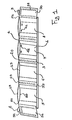
- La figure 1 représente, en vue perspective sommaire, un tel ensemble destiné à former barrage flottant.
- La figure 2 est une vue grossie d'une des poches caractéristique de ce barrage.
- Les figures 3 et 4 représentent sommairement deux modes de fixation de ce barrage aux berges d'un canal.
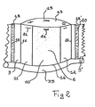
- La figure 5 est une représentation sommaire d'une enveloppe garnie de matière absorbante pulvérulente.
- Figure 1 shows, in summary perspective view, such an assembly intended to form a floating dam.
- Figure 2 is an enlarged view of one of the pockets characteristic of this dam.
- Figures 3 and 4 show briefly two methods of fixing this dam to the banks of a channel.
- FIG. 5 is a summary representation of an envelope filled with pulverulent absorbent material.
En se référant aux figures, le barrage anti-pollution flottant se compose d'un ensemble vertical (1) souple comprenant à chaque extrémité un fourreau tubulaire vertical d'amarrage (2) et (3), par exemple en tissu enduit souple, soudé ou cousu, à un complexe vertical (4) formé par une pluralité de poches successives juxtaposées ajourées (5-6-7 et 8). Ces poches élémentaires sont séparées entre elles par des portions verticales (9) étanches aux déchets à retenir, par exemple en tissu, notamment enduit ou en un film de matière synthétique souple. Ces poches (6-8) (voir figure 2) se composent essentiellement:
- - sur l'avant, d'une étoffe, tissée ou non, ajourée (10), bordée des deux côtés par une bande verticale (11) et (12) en un tissu enduit étanche aux déchets ou en un matériau similaire à (9);
- - sur l'arrière, d'une autre étoffe (13), tissée ou non, analogue et parallèle à (10), dont soit la maille du réseau est plus fine que celle de la face avant ou dont la surface est plus grande que celle de la face avant;
- - ces deux étoffes avant et arrière (10-13) sont soudées ou cousues sur le bas sur la ligne (14).
- - on the front, of a fabric, woven or not, perforated (10), bordered on both sides by a vertical strip (11) and (12) in a coated fabric impervious to waste or in a material similar to (9 );
- - on the back, of another fabric (13), woven or not, analogous and parallel to (10), whose mesh of the network is finer than that of the front face or whose surface is larger than that of the front face;
- - these two front and rear fabrics (10-13) are welded or sewn on the bottom on the line (14).
La poche élémentaire (6) ainsi formée, fermée sur le bas (14j, mais ouverte sur le haut en (15), est soudée par ses côtés (16-17) aux bandes de liaison (9-9'). Ces bandes de liaison (9-9') présentent un fourreau vertical (18-18') destiné à recevoir l'élément vertical de rigidification (19-20), formé par exemple par une latte en bois ou un tube bouché à ses extrémités.The elementary pocket (6) thus formed, closed at the bottom (14j, but open at the top at (15), is welded by its sides (16-17) to the connecting strips (9-9 '). link (9-9 ') have a vertical sheath (18-18') intended to receive the vertical stiffening element (19-20), formed for example by a wooden slat or a tube plugged at its ends.
Le haut de chaque poche (5-8) comporte des moyens de fermeture et des moyens d'ancrage de l'enveloppe (25) (figure 5) de matière absorbante (26), telles que par exemple des boutons pressions (21), des bandes adhésives à crochets (22) type Velcro (marque commerciale déposée), des oeillettons ou des boutons.The top of each pocket (5-8) comprises closing means and means for anchoring the envelope (25) (FIG. 5) of absorbent material (26), such as for example snaps (21), adhesive hooks (22) such as Velcro (registered trademark), eyelets or buttons.
La matière absorbante se présente sous la forme d'un sac ou d'une enveloppe poreuse (25), par exemple en un voile non tissé léger en fibres synthétiques. Cette enveloppe (25) qui a la forme d'un berlingot fermé à ses deux extrémités (27-28), contient la matière absorbante (26). Avantageusement, cette matière absorbante se présente sous forme pulvérulente. On peut utiliser toute matière connue pour ses propriétés absorbantes, telles que par exemple des pulpes de polyamide, des poudres de mousse de polyuré- thane ou des poudres de mousse de résine epo- xy broyée, tel que décrit dans la demande de brevet français n° 80/06 538 (FR-A-2 478 667) déposé le 24 Mars 1980.The absorbent material is in the form of a bag or a porous envelope (25), for example in a light non-woven veil of synthetic fibers. This envelope (25) which has the shape of a closed container at its two ends (27-28), contains the absorbent material (26). Advantageously, this absorbent material is in powder form. Any material known for its absorbent properties can be used, such as, for example, polyamide pulps, polyurethane foam powders or ground epoxy resin foam powders, as described in French patent application no. ° 80/06 538 (FR-A-2 478 667) filed on March 24, 1980.
Les extrémités de l'ensemble (1) formant barrage sont bordées par des bavettes verticales (30) et (31) également étanches aux déchets, réalisées avantageusement en un tissu enduit résistant aux hydrocarbures. Ces bavettes (30) et (31) peuvent être ou non rigidifiées par des lattes horizontales (32) ou verticales (33). Ces bavettes (30-31) sont articulées suivant la ligne de liaison verticale (50-51) avec l'ensemble (1) et sont destinées à assurer l'étanchéité de l'ensemble en prenant appui sur les rives ou sur les berges (40) du canal à traiter. En outre, ces bavettes assurent ainsi le passage obligatoire de l'eau polluée sur les parties ajourées des poches élémentaires et par voie de conséquence sur les enveloppes (25) contenant le matériau absorbant (26). De la sorte, le flux du courant à épurer est bien concentré sur le tissu ajouré (10) et par là sur tout le volume du coussin (25), même si celui-ci ne remplit pas complètement la poche élémentaire (6).The ends of the assembly (1) forming a dam are bordered by vertical flaps (30) and (31) also sealed against waste, advantageously made of a coated fabric resistant to hydrocarbons. These flaps (30) and (31) may or may not be stiffened by horizontal (32) or vertical (33) slats. These flaps (30-31) are articulated along the vertical connection line (50-51) with the assembly (1) and are intended to seal the assembly by resting on the banks or on the banks ( 40) of the channel to be treated. In addition, these flaps thus ensure the obligatory passage of polluted water over the perforated parts of the elementary pockets and consequently over the envelopes (25) containing the absorbent material (26). In this way, the flow of current to be purified is well concentrated on the perforated fabric (10) and thereby on the entire volume of the cushion (25), even if the latter does not completely fill the elementary pocket (6).
Le bas (14) de l'ensemble (1) comporte un fourreau tubulaire horizontal (35), destiné à recevoir un câble d'amarrage horizontal prenant appui sur chaque berge (40) et plus précisément sur les organes d'amarrage (42), (43). Si nécessaire, un second câble d'amarrage parallèle à celui-ci peut être placé sur le haut de l'ensemble.The bottom (14) of the assembly (1) comprises a horizontal tubular sheath (35), intended to receive a horizontal mooring cable bearing on each bank (40) and more precisely on the mooring members (42) , (43). If necessary, a second mooring cable parallel to it can be placed on the top of the assembly.
La mise en place de l'ensemble s'effectue de la manière suivante. Séparément, on remplit des enveloppes (25) d'une matière absorbante (26).The assembly of the assembly is carried out as follows. Separately, envelopes (25) are filled with an absorbent material (26).
Sur les rives ou sur les berges (40) (figure 3) d'un canal (41) à traiter, on enfonce ou on fixe par tout moyen connu, un organe d'amarrage vertical (42). Si la chose est possible, on peut aussi se contenter d'enfoncer (voir figure 4) un pieux vertical (43) dans le lit (44). Sur ces éléments d'amarrage (42-43-43'), on fait coulisser des anneaux (45, 46) destinés à accrocher le câble d'amarrage (47) qui traverse le lit et est enfilé dans le fourreau horizontal (35). On enfile ensuite les deux fourreaux verticaux latéraux (2-3) sur les pieux (43) verticaux ou analogues (42).On the banks or on the banks (40) (FIG. 3) of a channel (41) to be treated, a vertical mooring member (42) is pushed in or fixed by any known means. If this is possible, one can also be content to push (see Figure 4) a vertical pile (43) in the bed (44). On these mooring elements (42-43-43 '), rings (45, 46) are slid intended to hang the mooring cable (47) which passes through the bed and is threaded in the horizontal sleeve (35) . The two lateral vertical sleeves (2-3) are then threaded onto the vertical piles or similar (42).
Sous l'effet du courant, les bavettes d'extrémité (30) et (31) sont plaquées contre les berges (40).Under the effect of the current, the end flaps (30) and (31) are pressed against the banks (40).
Par un moyen quelconque (barque ou à pied), on pose les sacs (25) remplis de matière absorbante vierge (26) dans les poches élémentaires (6-8) ouvertes que l'on ferme ensuite (21-22).By any means (boat or on foot), the bags (25) filled with virgin absorbent material (26) are placed in the open elementary pockets (6-8) which are then closed (21-22).
Grâce aux bandes verticales étanches (9-11-12) et aux bavettes latérales étanches (30-31 les pollutions sont canalisées sur les portions poreuses (10), donc sur la matière absorbante (26) contenue dans l'enveloppe (25).Thanks to the sealed vertical strips (9-11-12) and the sealed lateral flaps (30-31) pollution is channeled onto the porous portions (10), therefore onto the absorbent material (26) contained in the envelope (25).
Si d'aventure le niveau d'eau varie, du fait de la densité des sacs (25), l'ensemble peut coulisser le long des pieux (42-43) grâce aux anneaux (45-46). Cet ensemble est donc auto-flottant.If by chance the water level varies, due to the density of the bags (25), the assembly can slide along the piles (42-43) thanks to the rings (45-46). This set is therefore self-floating.
On change les sacs (25) chargés de particules polluées selon un cycle déterminé ou s'il y a lieu, après une décharge accidentelle.The bags (25) loaded with polluted particles are changed according to a determined cycle or, if necessary, after an accidental discharge.
Le barrage selon l'invention présente de nombreux avantages par rapport aux barrages anti-pollution proposés à ce jour. On peut citer:
- - du fait de la souplesse générale, la possibilité d'être replié ou roulé sur lui-même, donc facilité de transport, de stockage et de montage;
- - la facilité d'exploitation, qui nécessite peu de personnel,
- - la possibilité de réaliser des barrages statiques, souples et à prix réduit;
- - la facilité de manipulation de l'élément absorbant qui se trouve dans des cartouches faciles à changer et à stocker;
- - la possibilité de réaliser des barrages auto- flottants, ce qui permet de suivre les variations du niveau de l'eau;
- - la possibilité de réaliser simultanément barrage et l'absorption, notamment pour les risées d'hydrocarbures.
- - because of the general flexibility, the possibility of being folded or rolled up on itself, therefore ease of transport, storage and assembly;
- - ease of operation, which requires few staff,
- - the possibility of making static, flexible dams at a reduced price;
- - the ease of handling of the absorbent element which is in cartridges which are easy to change and to store;
- - the possibility of making self-floating dams, which makes it possible to monitor variations in the water level;
- - the possibility of simultaneously carrying out a dam and absorption, in particular for hydrocarbon risées.
De la sorte, ce type de barrage peut être utilisé avantageusement pour lutter contre la pollution dans des rivières, dans des canaux, tels que par exemple dans les effluents d'eaux industrielles, d'eaux usées. On peut avantageusement les placer dans le canal d'entrée d'une station d'épuration d'eaux pluviales ou à la sortie d'un rejet d'aux usées.In this way, this type of dam can be used advantageously to fight against pollution in rivers, in canals, such as for example in the effluents of industrial water, of waste water. They can advantageously be placed in the inlet channel of a rainwater treatment plant or at the outlet of a wastewater discharge.
Claims (7)
characterized in that:
Applications Claiming Priority (2)
| Application Number | Priority Date | Filing Date | Title |
|---|---|---|---|
| FR8218373A FR2535362A1 (en) | 1982-10-28 | 1982-10-28 | ANTI-POLLUTION FILTERING FLOATING DAM |
| FR8218373 | 1982-10-28 |
Publications (2)
| Publication Number | Publication Date |
|---|---|
| EP0108024A1 EP0108024A1 (en) | 1984-05-09 |
| EP0108024B1 true EP0108024B1 (en) | 1985-12-27 |
Family
ID=9278844
Family Applications (1)
| Application Number | Title | Priority Date | Filing Date |
|---|---|---|---|
| EP83420163A Expired EP0108024B1 (en) | 1982-10-28 | 1983-10-13 | Floating and filtering anti-pollution barrier |
Country Status (4)
| Country | Link |
|---|---|
| EP (1) | EP0108024B1 (en) |
| DE (1) | DE3361646D1 (en) |
| FR (1) | FR2535362A1 (en) |
| OA (1) | OA07573A (en) |
Families Citing this family (7)
| Publication number | Priority date | Publication date | Assignee | Title |
|---|---|---|---|---|
| FR2641584B1 (en) * | 1988-01-18 | 1991-05-10 | Caoutchouc Manuf Plastique | IMPROVEMENT TO A DEVICE FOR JOINING PANELS OR MAKING CONDUITS |
| NO165968C (en) * | 1988-10-27 | 1991-05-15 | Norva Invest As | OIL COLLECTING. |
| CA2120758A1 (en) * | 1992-03-25 | 1993-04-15 | Alan R. Hill | Oil absorption method and apparatus utilizing a replaceable bladder |
| US7054648B2 (en) | 2001-10-22 | 2006-05-30 | Telefonaktiebolaget Lm Ericsson (Publ) | Location privacy proxy server and method in a telecommunication network |
| DE102019002084A1 (en) * | 2018-09-25 | 2020-03-26 | Wolfgang Zachert | Keratin bag, keratin filter, keratin pad, keratin scattering material, keratin precautionary tool, keratin heat and cold insulation, radioactive insulation, new future energy source |
| WO2025240987A1 (en) | 2024-05-22 | 2025-11-27 | Miba Frictec Gmbh | Multiple-disc brake |
| CN119857292B (en) * | 2025-03-20 | 2025-05-30 | 上海金山环境再生能源有限公司 | A filtering device for leachate |
Family Cites Families (4)
| Publication number | Priority date | Publication date | Assignee | Title |
|---|---|---|---|---|
| US3739913A (en) * | 1970-07-16 | 1973-06-19 | Johns Manville | Device for fencing and absorbing contaminating oil spills on water |
| US3702657A (en) * | 1971-02-11 | 1972-11-14 | Exxon Production Research Co | Pollution containment barrier |
| FR2163836A5 (en) * | 1971-12-03 | 1973-07-27 | Rebut Paul | Oil slick collector - from tubular woven elements |
| CA1048799A (en) * | 1976-10-05 | 1979-02-20 | Paul Preus | Barrier construction for water carried pollutants |
-
1982
- 1982-10-28 FR FR8218373A patent/FR2535362A1/en active Granted
-
1983
- 1983-10-13 EP EP83420163A patent/EP0108024B1/en not_active Expired
- 1983-10-13 DE DE8383420163T patent/DE3361646D1/en not_active Expired
- 1983-10-26 OA OA58144A patent/OA07573A/en unknown
Also Published As
| Publication number | Publication date |
|---|---|
| EP0108024A1 (en) | 1984-05-09 |
| OA07573A (en) | 1985-03-31 |
| DE3361646D1 (en) | 1986-02-06 |
| FR2535362B1 (en) | 1985-03-08 |
| FR2535362A1 (en) | 1984-05-04 |
Similar Documents
| Publication | Publication Date | Title |
|---|---|---|
| EP0108024B1 (en) | Floating and filtering anti-pollution barrier | |
| CA2175088A1 (en) | Boom system | |
| FR2465510A1 (en) | FILTER FOR EXCREMENT COLLECTOR DEVICE | |
| KR102332673B1 (en) | Device for collecting spilled oil by separating oil and water, oil fence using the same, and jellyfish blocking device using the same | |
| BE1009089A5 (en) | Multi-fold structure for work early intervention. | |
| EP0500723A1 (en) | FLOATING BARRIER. | |
| EP1570131B1 (en) | Device for collecting items floating at the surface of the sea | |
| US5348661A (en) | Oil absorption method and apparatus utilizing a replaceable bladder | |
| KR101527361B1 (en) | Apparatus comprising curtain using dcilia meadia to block green algae | |
| FR2552133A1 (en) | Modular barrage filtering out water pollution | |
| FR2913418A1 (en) | Module for purifying effluent, comprises tank having bottom from which peripheral belt is uplifted, biological filtration medium, unit for supplying effluent to biological filtration medium, and unit to recover purified effluent | |
| JPH1077622A (en) | Flood control sack body | |
| US20110198273A1 (en) | Multi-stage storm drain filter insert | |
| FR2719785A1 (en) | Bag for handling biological samples including filter | |
| JP2000328548A (en) | Oil fence | |
| FR2467263A1 (en) | ACTIVE FLOATING DAM USED FOR DEPOLLUTION | |
| BE1004523A3 (en) | Device air cleaner. | |
| JP3191073U (en) | Flexible container bag | |
| FR2783006A1 (en) | MIXED ISOTHERMAL AND SAFETY ROLL-UP COVER FOR POOLS | |
| KR101130918B1 (en) | A water treatment system by non-efflux self-weight water pressure filteration using elvan | |
| CA1146365A (en) | Anti-pollution barrier | |
| CA2495976C (en) | Fluid flow control barrier | |
| EP2868821B1 (en) | Gully with filter device | |
| FR2633274A1 (en) | Flexible device acting as a dam for cleaning polluted water surfaces | |
| KR20250094332A (en) | Removing hazardous algae device capable of recovering adsorption materials and the hazardous algae |
Legal Events
| Date | Code | Title | Description |
|---|---|---|---|
| PUAI | Public reference made under article 153(3) epc to a published international application that has entered the european phase |
Free format text: ORIGINAL CODE: 0009012 |
|
| AK | Designated contracting states |
Designated state(s): BE DE IT NL |
|
| 17P | Request for examination filed |
Effective date: 19840524 |
|
| GRAA | (expected) grant |
Free format text: ORIGINAL CODE: 0009210 |
|
| AK | Designated contracting states |
Designated state(s): BE DE IT NL |
|
| PG25 | Lapsed in a contracting state [announced via postgrant information from national office to epo] |
Ref country code: NL Effective date: 19851227 Ref country code: IT Free format text: LAPSE BECAUSE OF FAILURE TO SUBMIT A TRANSLATION OF THE DESCRIPTION OR TO PAY THE FEE WITHIN THE PRESCRIBED TIME-LIMIT;WARNING: LAPSES OF ITALIAN PATENTS WITH EFFECTIVE DATE BEFORE 2007 MAY HAVE OCCURRED AT ANY TIME BEFORE 2007. THE CORRECT EFFECTIVE DATE MAY BE DIFFERENT FROM THE ONE RECORDED. Effective date: 19851227 |
|
| REF | Corresponds to: |
Ref document number: 3361646 Country of ref document: DE Date of ref document: 19860206 |
|
| NLV1 | Nl: lapsed or annulled due to failure to fulfill the requirements of art. 29p and 29m of the patents act | ||
| PLBE | No opposition filed within time limit |
Free format text: ORIGINAL CODE: 0009261 |
|
| STAA | Information on the status of an ep patent application or granted ep patent |
Free format text: STATUS: NO OPPOSITION FILED WITHIN TIME LIMIT |
|
| 26N | No opposition filed | ||
| PG25 | Lapsed in a contracting state [announced via postgrant information from national office to epo] |
Ref country code: BE Effective date: 19871031 |
|
| BERE | Be: lapsed |
Owner name: BAT TARAFLEX Effective date: 19871031 |
|
| PG25 | Lapsed in a contracting state [announced via postgrant information from national office to epo] |
Ref country code: DE Effective date: 19880701 |