EP0107473A2 - Einstellbare Schlittenantriebsvorrichtung - Google Patents
Einstellbare Schlittenantriebsvorrichtung Download PDFInfo
- Publication number
- EP0107473A2 EP0107473A2 EP83306321A EP83306321A EP0107473A2 EP 0107473 A2 EP0107473 A2 EP 0107473A2 EP 83306321 A EP83306321 A EP 83306321A EP 83306321 A EP83306321 A EP 83306321A EP 0107473 A2 EP0107473 A2 EP 0107473A2
- Authority
- EP
- European Patent Office
- Prior art keywords
- lever
- carriage
- connector member
- threaded rod
- combination
- Prior art date
- Legal status (The legal status is an assumption and is not a legal conclusion. Google has not performed a legal analysis and makes no representation as to the accuracy of the status listed.)
- Granted
Links
- 230000007246 mechanism Effects 0.000 title abstract description 14
- 238000007639 printing Methods 0.000 claims abstract description 66
- 238000007650 screen-printing Methods 0.000 claims abstract description 12
- 230000001419 dependent effect Effects 0.000 claims 1
- 238000006073 displacement reaction Methods 0.000 abstract 1
- 239000003638 chemical reducing agent Substances 0.000 description 2
- 230000032258 transport Effects 0.000 description 2
- 230000004075 alteration Effects 0.000 description 1
- 230000008859 change Effects 0.000 description 1
- 238000010276 construction Methods 0.000 description 1
- 230000004048 modification Effects 0.000 description 1
- 238000012986 modification Methods 0.000 description 1
Images

Classifications
-
- B—PERFORMING OPERATIONS; TRANSPORTING
- B41—PRINTING; LINING MACHINES; TYPEWRITERS; STAMPS
- B41F—PRINTING MACHINES OR PRESSES
- B41F15/00—Screen printers
- B41F15/14—Details
- B41F15/40—Inking units
- B41F15/42—Inking units comprising squeegees or doctors
- B41F15/423—Driving means for reciprocating squeegees
Definitions
- the present invention relates generally to screen printing presses and relates more particularly to an improved carriage drive mechanism for use in a screen printing press.
- ink is applied to a sheet of stock by a squeegee which is carried in reciprocating motion along a printing head by a carriage.
- Printing occurs as the carriage travels from the front of the head to the rear of the head.
- the carriage Upon reaching the rear of the printing head, the carriage reverses direction and carries the squeegee back to its starting point at the front of the printing head.
- the path of the carriage from the front to the rear of the printing head is the printing stroke.
- Such apparatus generally includes an electric motor which transmits motion to the carriage through some type of mechanical linkage.
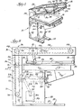
- the present invention is generally embodied in a screen printing press 10 having a press frame,indicated generally at 12, supporting a pivoting printing head 14 and a generally horizontal printing bed 16.
- the frame includes a pair of horizontal base members 13 and a pair of vertical members 15 (FIGURE 2) which are positioned at the rear of the press.
- the portion of the press beneath the printing bed is enclosed by a housing 18 which includes an upstanding front wall 20 and a pair of upstanding side walls 22 adjacent the front wall.
- the printing head 14 includes a pair of side members 24 extending along its opposite sides and a rear transverse member 28 which joins the side members 24 at their rear ends.
- a printing screen 29 stretched in a rectangular screen frame 30 is positioned above the printing bed 16.
- the screen frame 30 is supported at its four corners by brackets 31 depending from the printing head 14.
- the printing head is positioned horizontally above the bed 16 and a squeegee 32 which spans the width of the printing head 14 is carried longitudinally along the printing head over the screen by a carriage 34 which is supported at its opposite ends by the side members 24 of the printing head.
- the printing head 14 is mounted upon upwardly extending pivot arms 35 which are supported at their lower ends by the upstanding members 15 of the press frame 12 at the rear of the press.
- the squeegee carriage 34 is shifted forwardly and rearwardly by a carriage drive means 36 which, in this instance, includes a pair of chains 52 to which opposite ends of the squeege carriage are connected.
- the cahins 52 run horizontally when the printing head is closed, as seen in FIGURE 2, and a vertical drive means 37 including chains 66 and 72 drive the squeegee chains through the printing stroke.
- the vertical chains 66 and 72 are, in turn, driven through an adjustable linkage means 41 which is driven by a motor drive means comprising a motor 43 and a speed reducer 39.
- the conventional linkage means has heretofore been adjustable by stopping the press and removing the access covers to the internal drive of the press and then to adjusting the linkage means usually by unbolting a pivot connection between a crank and lever and then rebolting the crank and lever at a new position so that the movement of the vertical drive means 37 and the carriage drive chains 52 was varied incrementally.
- the operator could not view the results of such changes in the linkage and also the resultant variation in printing stroke until the machine was again placed in operation. If further adjustment was desired, the machine had to be stopped and another adjustment made to the linkage.
- the motor means drives the linkage means which includes a pivoted driving lever 38.
- the drive lever 38 is pivotally mounted on a fixed support 45 at one end and pivotally connected to the chain drive 36 at the opposite end.
- the drive lever 38 is pivoted by the motor 43 which is connected to a speed reducer 39 which turns a rotating crankshaft 40 with a crank 42 fixed to its end.
- a crank link 44 connects the crank to the drive lever.
- the crank link 44 is pivotally connected to a pin 46 projecting from the drive lever at an intermediate point. Rotation of the crankshaft 40 causes the drive lever to pivot, imparting reciprocating motion to the chain drive 36 and thus moving the squeegee 32 and carriage 34 reciprocally along the printing head.
- an improved carriage drive mechanism which is adjustable from the exterior of the press and which enables the stroke length to be altered quickly and conveniently, without interrupting the operation of the press.
- means are provided for mechanically altering the configuration of the lever mechanism which transmits power from the crankshaft 40 to the chain drive 36 by displacing a movable connector means including a member 48 longitudinally along the pivoting drive lever 38.
- the pin 46 which provides the pivotal connection between the crank link 44 and the drive lever 38 is fixed to the movable connector 48 which is mounted upon a threaded rod 50 disposed longitudinally within the drive lever 38.
- Rotation of the threaded rod 50 about its longitudinal axis moves the connector 48 longitudinally upon the threaded rod, changing the point at which the crank link 44 is connected to the drive lever 38.
- the threaded rod 50 is connected to a handle 106 mounted on the exterior of the machine to be turned by the operator who may view the results of the change of the printing stroke. Rotation of the handle 106 changes the length of the stroke of the drive lever 38, and thereby alters the length of the printing stroke.
- the threaded rod 50 provides a continuous or infinite range of adjustment to enable fine adjustments to be made while the operator watches.
- the carriage 34 is attached at its opposite ends to the carriage chains 52 which extend the length of the printing head.
- Each carriage chain is supported by front and rear carriage chain sprockets 54 and 56 respectively.
- the carriage 34 is attached'by pins 61 to an upper portion 62 of each chain 52.
- the front sprockets are rotatably supported by the side members 24 of the printing head 14.
- the rear sprockets 56 are fixed to an upper drive shaft 58 which extends across the rear of the printing head 14 and is journaled at its opposite ends through the side members 24.
- an upper drive sprocket 64 is fixed to the upper drive shaft 58 between the rear carriage chain sprockets 56 to transmit rotation to the upper drive shaft 58 from an upper drive chain 66 which extends vertically downward from the upper drive sprocket 64 to a first intermediate drive sprocket 68 which is fixed to an intermediate drive shaft 70.
- the intermediate drive shaft 70 is rotatably supported by the rear frame members 15.
- a lower drive chain 72 is looped about a second intermediate drive sprocket 74 which is fixed to the intermediate drive shaft 70 and a lower drive sprocket 76 which is fixed to a lower shaft 78 which is rotatably supported at its ends by the frame members 15.
- the drive lever 38 herein includes a generally rectangular bottom wall 80 to which are affixed two upwardly extending side walls 82 and an upwardly extending rear wall 86.
- a generally horizontal shaft 88 extends transversely through circular apertures 90 in the forward ends of the side walls 82 to provide a pivot axis for the drive lever 38.
- the shaft 88 is rotatably supported at its opposite ends by bearings 92 which are supported by the frame 12.
- a transverse bore 94 is formed centrally through the shaft 88 to receive the threaded rod 50 which is disposed longitudinally between the side walls 82 of the drive lever 38.
- the connector 48 which is mounted on the threaded rod 50 includes a centrally perforated nut 96 having a threaded bore 97 ( Figure 4) to receive the threaded rod 50 and includes a pair of generally cylindrical side lugs 98 which extend outwardly through arcuate slots 100 in the side walls 82 of the drive lever.
- the pin 46 which provides the pivotal connection between the crank link 44 and the drive lever 38 extends beyond the end of one of the lugs 98.
- the drive lever 38 is connected to the lower drive chain 72 by an upwardly extending lug 102 which is fixed to the drive lever 38 near the rear of one of the side walls and pivotally attached at its upper end to an upper end of a short link 104.
- the link 104 is pivotally connected at its lower end by a pin 105 to the lower drive chain 72.
- the crankshaft 40 is rotated at a predetermined speed by the motor.
- the rotation of the crankshaft 40 moves the drive lever 38 in reciprocal pivoting motion between a horizontal position and a downwardly inclined position, thus rotating the drive chains 72 and 66 and carriage chains 52 to transport the carriage 34 reciprocally between the front and the rear of the printing head 14.
- Printing occurs as the carriage 34 transports the squeegee 32 over the upper surface of the screen 29 toward the rear of the printing head.
- the drive lever 38 is in the horizontal position when the carriage 34 is at the rearmost position.
- the drive lever 38 pivots downward as the carriage 34 returns toward the front of the printing head 14.
- the press operator rotates the threaded rod 50 about its longitudinal axis, moving the connector 48 through the arcuate path defined by the slots 100 in the side walls 82. Moving the conector toward the horizontal shaft 88 lengthens the pivoting stroke. Moving the connector away from the shaft 88 shortens the printing stroke.
- the front end 105 of the threaded rod 50 extends through the front wall 20 of the press housing 18 so that rotation of the threaded rod 50 may be accomplished by turning an external hand crank 106 which is fixed to the front end of the threaded rod.
- the threaded rod 50 could alternatively be connected to a gearbox (not shown) and rotated by a crank placed at a different location or by a small electric motor.
- the arcuate slots 100 formed in the side walls 82 of the drive lever 38 are configured to position the drive lever in approximately the same position at end of the printing stroke regardless of the position of the connector 48 on the threaded rod 50 so that alteration of the length of the printing stroke alters the starting position of the carriage without substantially changing the ending position.
- variation of the stroke length corresponds to variation of the lowermost pivoted position of the drive lever 38, which corresponds to variation of the starting point of the printing stroke.
- the above-described silk screen printing press employes pivoting printing head and employes chains 52 to drive the squeegee carriage through the printing stroke. It is to be appreciated that other silk screen printing presses have printing heads which are pivotal between open and close positions and that the present invention could be used therewith. Further, the illustrated and preferred vertical chains 66 and 72 could be replaced with other mechanical drives. The present invention however is particularly adapted for use with the vertical chain drives as disclosed herein.
- the present invention provides an improved adjustable carriage drive mechanism which may be conveniently adjusted from the exterior of the press without interrupting operation of the press and which enables fine adjustments in stroke length to be made. While a preferred embodiment has been shown and described, there is no intent to limit the invention by this disclosure. The invention encompasses all modifications and alternate constructions falling within the spirit and scope of the invention as defined in the appended claims.
Landscapes
- Engineering & Computer Science (AREA)
- Mechanical Engineering (AREA)
- Screen Printers (AREA)
Applications Claiming Priority (2)
| Application Number | Priority Date | Filing Date | Title |
|---|---|---|---|
| US436834 | 1982-10-26 | ||
| US06/436,834 US4524687A (en) | 1982-10-26 | 1982-10-26 | Adjustable carriage drive mechanism |
Publications (3)
| Publication Number | Publication Date |
|---|---|
| EP0107473A2 true EP0107473A2 (de) | 1984-05-02 |
| EP0107473A3 EP0107473A3 (en) | 1985-05-22 |
| EP0107473B1 EP0107473B1 (de) | 1987-06-24 |
Family
ID=23734008
Family Applications (1)
| Application Number | Title | Priority Date | Filing Date |
|---|---|---|---|
| EP83306321A Expired EP0107473B1 (de) | 1982-10-26 | 1983-10-18 | Einstellbare Schlittenantriebsvorrichtung |
Country Status (4)
| Country | Link |
|---|---|
| US (1) | US4524687A (de) |
| EP (1) | EP0107473B1 (de) |
| JP (1) | JPS5995144A (de) |
| DE (1) | DE3372192D1 (de) |
Families Citing this family (3)
| Publication number | Priority date | Publication date | Assignee | Title |
|---|---|---|---|---|
| US4919043A (en) * | 1988-10-04 | 1990-04-24 | American Screen Printing Company | Web tech drive assembly for stencil carriage |
| US4958559A (en) * | 1988-10-04 | 1990-09-25 | American Screen Printing Company | Cylinder press drive assembly |
| US20090320711A1 (en) * | 2004-11-29 | 2009-12-31 | Lloyd Richard M | Munition |
Family Cites Families (18)
| Publication number | Priority date | Publication date | Assignee | Title |
|---|---|---|---|---|
| US3118318A (en) * | 1964-01-21 | Arrangement for periodically varying the | ||
| US1589546A (en) * | 1925-06-18 | 1926-06-22 | Nichols Elmer | Printing machine |
| DE481957C (de) * | 1926-02-11 | 1929-09-03 | Albert Henry Franks Perl | Vorrichtung zur Umwandlung einer drehenden in eine hin und her gehende Bewegung |
| US1776459A (en) * | 1928-03-05 | 1930-09-23 | Western Lithograph Company | Apparatus for making stencil prints |
| GB600212A (en) * | 1944-12-01 | 1948-04-02 | Solar Lab | Improvements in or relating to machines for decorating articles, such as hollow-ware |
| US2640415A (en) * | 1950-05-31 | 1953-06-02 | Screen Printing Machinery Ltd | Mechanism for transforming one form of movement into another, more particularly for use in stencil printing machines |
| US2894451A (en) * | 1956-09-04 | 1959-07-14 | Landesman Eugene | Screen printing machine |
| US3220344A (en) * | 1961-10-27 | 1965-11-30 | Hagerman Dorothy | Turret type bottle stenciling device |
| US3166011A (en) * | 1962-10-15 | 1965-01-19 | Landesman Eugene | Screen printing machine with oscillating stencil frame |
| US3159100A (en) * | 1963-02-08 | 1964-12-01 | Monsanto Co | Method and apparatus for forming indicia on articles |
| US3237555A (en) * | 1964-02-28 | 1966-03-01 | Liberty Glass Co | Apparatus for printing on articles such as bottles or the like |
| US3731623A (en) * | 1970-10-26 | 1973-05-08 | American Screen Process Equip | Glider press |
| US3838639A (en) * | 1970-12-08 | 1974-10-01 | D Yoder | Screen printing apparatus |
| US3859917A (en) * | 1972-10-24 | 1975-01-14 | American Screen Printing | Screen printing press |
| US3955501A (en) * | 1974-01-23 | 1976-05-11 | American Screen Printing Equipment Company | Squeegee and flood bar actuator |
| US4068579A (en) * | 1976-02-02 | 1978-01-17 | Ventura International, Inc. | Cylindrical container silk screen printer with coordinated screen height and stroke adjustment indexing mechanism |
| FR2370587A1 (fr) * | 1976-11-15 | 1978-06-09 | Monvoisin Jacques | Machine automatique pour la realisation d'impressions en serigraphie |
| US4254708A (en) * | 1978-06-23 | 1981-03-10 | American Screen Printing Equipment Company | Mechanical drive screen printing press |
-
1982
- 1982-10-26 US US06/436,834 patent/US4524687A/en not_active Expired - Fee Related
-
1983
- 1983-10-18 DE DE8383306321T patent/DE3372192D1/de not_active Expired
- 1983-10-18 EP EP83306321A patent/EP0107473B1/de not_active Expired
- 1983-10-26 JP JP58200700A patent/JPS5995144A/ja active Pending
Also Published As
| Publication number | Publication date |
|---|---|
| US4524687A (en) | 1985-06-25 |
| DE3372192D1 (en) | 1987-07-30 |
| EP0107473A3 (en) | 1985-05-22 |
| EP0107473B1 (de) | 1987-06-24 |
| JPS5995144A (ja) | 1984-06-01 |
Similar Documents
| Publication | Publication Date | Title |
|---|---|---|
| US3955501A (en) | Squeegee and flood bar actuator | |
| JPH1044374A (ja) | 版板を軸方向で位置決めするための方法および装置 | |
| US3263603A (en) | Silk screen printing apparatus | |
| US4493254A (en) | Screen printing machine and drive system therefor | |
| US4513663A (en) | Mechanism for varying the axial travel of a distributing roller in a printing machine | |
| US4524687A (en) | Adjustable carriage drive mechanism | |
| US4520726A (en) | Flat silk-screen printing machine with movable pivoted support | |
| US5372066A (en) | Multiple feed cylinder press | |
| KR940005362B1 (ko) | 쌍바늘 재봉틀로 이중 솔기 코너를 재봉하는 방법 | |
| US3885493A (en) | Printing head construction for use in a screen printing machine | |
| US4589649A (en) | Oscillating sheet separating suction head on parallelogram linkage | |
| KR100285288B1 (ko) | 라벨 자동 절단장치 | |
| US3838639A (en) | Screen printing apparatus | |
| US4413559A (en) | Multi-speed drive for screen printing presses | |
| US3545377A (en) | Screen printing apparatus | |
| CN117734296A (zh) | 全自动无纺布双色丝网印刷机 | |
| US4240343A (en) | Automatic machine for serigraphic printing | |
| GB2257126A (en) | Cardboard box assembly machines | |
| JPH09314801A (ja) | シリンダ型スクリーン印刷機におけるスクリーン版の印刷ストローク補正装置 | |
| CS250525B1 (en) | Device for inking unit's rubbing-down rollers' axial shifting | |
| US4951566A (en) | Screen printing apparatus | |
| US2810340A (en) | Silk screen printing machine | |
| KR20010102897A (ko) | 라벨 인쇄장치 | |
| JPH11300442A (ja) | テーパ管の製造装置 | |
| JPH0248467B2 (de) |
Legal Events
| Date | Code | Title | Description |
|---|---|---|---|
| PUAI | Public reference made under article 153(3) epc to a published international application that has entered the european phase |
Free format text: ORIGINAL CODE: 0009012 |
|
| AK | Designated contracting states |
Designated state(s): DE FR GB IT SE |
|
| PUAL | Search report despatched |
Free format text: ORIGINAL CODE: 0009013 |
|
| AK | Designated contracting states |
Designated state(s): DE FR GB IT SE |
|
| 17P | Request for examination filed |
Effective date: 19850822 |
|
| 17Q | First examination report despatched |
Effective date: 19860916 |
|
| ITF | It: translation for a ep patent filed | ||
| GRAA | (expected) grant |
Free format text: ORIGINAL CODE: 0009210 |
|
| AK | Designated contracting states |
Kind code of ref document: B1 Designated state(s): DE FR GB IT SE |
|
| REF | Corresponds to: |
Ref document number: 3372192 Country of ref document: DE Date of ref document: 19870730 |
|
| ET | Fr: translation filed | ||
| PLBE | No opposition filed within time limit |
Free format text: ORIGINAL CODE: 0009261 |
|
| STAA | Information on the status of an ep patent application or granted ep patent |
Free format text: STATUS: NO OPPOSITION FILED WITHIN TIME LIMIT |
|
| 26N | No opposition filed | ||
| PGFP | Annual fee paid to national office [announced via postgrant information from national office to epo] |
Ref country code: SE Payment date: 19890927 Year of fee payment: 7 Ref country code: FR Payment date: 19890927 Year of fee payment: 7 |
|
| ITTA | It: last paid annual fee | ||
| PGFP | Annual fee paid to national office [announced via postgrant information from national office to epo] |
Ref country code: GB Payment date: 19891031 Year of fee payment: 7 |
|
| PGFP | Annual fee paid to national office [announced via postgrant information from national office to epo] |
Ref country code: DE Payment date: 19891107 Year of fee payment: 7 |
|
| PG25 | Lapsed in a contracting state [announced via postgrant information from national office to epo] |
Ref country code: GB Effective date: 19901018 |
|
| PG25 | Lapsed in a contracting state [announced via postgrant information from national office to epo] |
Ref country code: SE Effective date: 19901019 |
|
| GBPC | Gb: european patent ceased through non-payment of renewal fee | ||
| PG25 | Lapsed in a contracting state [announced via postgrant information from national office to epo] |
Ref country code: FR Effective date: 19910628 |
|
| PG25 | Lapsed in a contracting state [announced via postgrant information from national office to epo] |
Ref country code: DE Effective date: 19910702 |
|
| REG | Reference to a national code |
Ref country code: FR Ref legal event code: ST |
|
| EUG | Se: european patent has lapsed |
Ref document number: 83306321.7 Effective date: 19910603 |