EP0106673A2 - Optical and reversible recording and reproducing apparatus - Google Patents
Optical and reversible recording and reproducing apparatus Download PDFInfo
- Publication number
- EP0106673A2 EP0106673A2 EP83306198A EP83306198A EP0106673A2 EP 0106673 A2 EP0106673 A2 EP 0106673A2 EP 83306198 A EP83306198 A EP 83306198A EP 83306198 A EP83306198 A EP 83306198A EP 0106673 A2 EP0106673 A2 EP 0106673A2
- Authority
- EP
- European Patent Office
- Prior art keywords
- optical
- light
- signals
- light spot
- recording
- Prior art date
- Legal status (The legal status is an assumption and is not a legal conclusion. Google has not performed a legal analysis and makes no representation as to the accuracy of the status listed.)
- Granted
Links
Images


Classifications
-
- G—PHYSICS
- G11—INFORMATION STORAGE
- G11B—INFORMATION STORAGE BASED ON RELATIVE MOVEMENT BETWEEN RECORD CARRIER AND TRANSDUCER
- G11B7/00—Recording or reproducing by optical means, e.g. recording using a thermal beam of optical radiation by modifying optical properties or the physical structure, reproducing using an optical beam at lower power by sensing optical properties; Record carriers therefor
- G11B7/12—Heads, e.g. forming of the optical beam spot or modulation of the optical beam
- G11B7/125—Optical beam sources therefor, e.g. laser control circuitry specially adapted for optical storage devices; Modulators, e.g. means for controlling the size or intensity of optical spots or optical traces
-
- G—PHYSICS
- G11—INFORMATION STORAGE
- G11B—INFORMATION STORAGE BASED ON RELATIVE MOVEMENT BETWEEN RECORD CARRIER AND TRANSDUCER
- G11B7/00—Recording or reproducing by optical means, e.g. recording using a thermal beam of optical radiation by modifying optical properties or the physical structure, reproducing using an optical beam at lower power by sensing optical properties; Record carriers therefor
- G11B7/004—Recording, reproducing or erasing methods; Read, write or erase circuits therefor
- G11B7/0055—Erasing
- G11B7/00557—Erasing involving phase-change media
-
- G—PHYSICS
- G11—INFORMATION STORAGE
- G11B—INFORMATION STORAGE BASED ON RELATIVE MOVEMENT BETWEEN RECORD CARRIER AND TRANSDUCER
- G11B7/00—Recording or reproducing by optical means, e.g. recording using a thermal beam of optical radiation by modifying optical properties or the physical structure, reproducing using an optical beam at lower power by sensing optical properties; Record carriers therefor
- G11B7/007—Arrangement of the information on the record carrier, e.g. form of tracks, actual track shape, e.g. wobbled, or cross-section, e.g. v-shaped; Sequential information structures, e.g. sectoring or header formats within a track
- G11B7/00745—Sectoring or header formats within a track
-
- G—PHYSICS
- G11—INFORMATION STORAGE
- G11B—INFORMATION STORAGE BASED ON RELATIVE MOVEMENT BETWEEN RECORD CARRIER AND TRANSDUCER
- G11B7/00—Recording or reproducing by optical means, e.g. recording using a thermal beam of optical radiation by modifying optical properties or the physical structure, reproducing using an optical beam at lower power by sensing optical properties; Record carriers therefor
- G11B7/08—Disposition or mounting of heads or light sources relatively to record carriers
Definitions
- This invention relates to an optical recording and reproducing apparatus and, more particularly, to an optical and reversible recording and reproducing apparatus in which a laser beam is converged to a micro-lightbeam having a diameter of about 1 pm using a lens or the like and this micro-lightbeam is applied onto an optical recording medium to record and reproduce signals with high density and to erase the recorded signals, thereby to permit repetitional recording and reproducing of the signals.
- optical recording and reproducing apparatus Conventionally, as one example of optical recording and reproducing apparatus, an apparatus has been proposed and used in which signals are recorded and reproduced with high density by applying a laser beam or the like having the above-mentioned micro-beam diameter on an optical recording disc which is rotating.
- This kind of optical recording and reproducing apparatus is highlighted as an apparatus which can provide a new recording device and media for future society that will be filled with great amount of information in view of advantages of apparatus of this kind that the recording . density is high and, therefore, the memory cost per one bit can be.reduced, that the access time is very short and that the recording and reproducing can be stably performed since an optical head does not come into contact with the tracks of the optical recording disc.
- the write-once type and the erasable type have been proposed.
- a write-once type recording and reproducing method there has been proposed one method of recording and reproducing signals in which the thin recording film is locally evaporated by the thermal energy of the lasers to form small holes, and another method of recording and reproducing signals in which the optical density of the thin recording film is locally changed by the thermal energy of the laser beam, or the like.
- an optical recording and reproducing apparatus of the erasable type there have been proposed a first method in which a magnetic optical recording material is used to record and reproduce signals, in cooperation with the thermal effect of the laser, and an external magnetic field is used, and a second method in which with respect to the thin recording film whose optical density is changed as mentioned above, the optical density is reversibly changed only by using the thermal energy of the laser. It is worth noting that because the optical density can be reversibly changed, signals can be erasably recorded and reproduced on and from an optical recording medium.
- a transition between the amorphous state and the crystal state of the thin recording film, or a transition between one amorphous state and another stable amorphous state is repeatedly carried out. Additionally, there is also proposed a method in which a change in size of the crystal partiles in an amorphous matrix is utilized.
- F ig. 1 shows a simplified model of the condition for transition between the amorphous state and the crystal state.
- the amorphous state is indicated by a reference character (A), in which the reflection factor of the light of the thin recording film is small, while the transmission factor of the light is large.
- the crystal state is represented by (C), in which the reflection factor of the thin recording film is large, but the transmission factor is small.
- Figs. 2a and 2b show examples of method of realizing the condition to raise-the temperature and cool rapidly and the condition to raise the temperature and cool slowly on the thin recording film.
- Fig. 2a shows an almost circular micro spot L to be formed by the laser or the like on the recording medium which relatively moves in the direction indicates by an arrow.
- the intensity of this light spot L is enlarged for only a short period of time to raise the temperature of a local portion of the thin film, the thermal energy due to this temperature elevation at this local portion will be rapidly diffused to the thin film and the supporting member of the thin film, thereby providing the rapid cooling condition.
- Fig. 2a shows an almost circular micro spot L to be formed by the laser or the like on the recording medium which relatively moves in the direction indicates by an arrow.
- a more specific object of the present invention is to provide such a novel apparatus in which a substantially circular light spot, as the above-mentioned first light spot, and an eliptic light spot, as the above-mentioned second sport, having a different wave length from that of the first light elongated along the guide track are closely arranged on the same guide track in the optical disc using the same diaphragm lens, and in which signals can be recorded and reproduced, using the first light spot and the already recorded signals can be erased by providing the condition for temperature elevation and slow cooling for the thin recording film using solely the second light spot or cooperatively using both first and second light spots.
- a further object of the invention is to provide such a novel apparatus in which the format information recorded on the optical recording disc is read out and the interval to be erased on the optical recording disc, i.e. the erasing region is detected and fixed by the first light spot, and in which the erasing light constituted by the second light spot and the like can irradiate on only the specific interval to be read out by the first light spot.
- Fig. 3 is a cross sectional view in the radial direction of an optical recording disc ..aving guide tracks (pregrooves disc) to be used for the present invention.
- guide tracks pregrooves disc
- an optical pregrooves disc having grooves in the entire surface of the signal recording area on the disc.
- a disc substrate 50 is made of a transparent material, on which groves 51 each having a width w, depth d and track pitch p are formed spirally or coaxially.
- a thin recording film 52 having a thickness t is formed by the metal evaporating process or other process on the disc substrate 50.
- a protective layer 53 is further formed on this film 52.
- Each width w of the grooves 51 is smaller than the diameter of a laser beam 54 to be irradiated.
- the depth d of each groove is selected to be such a value that when the center of the optical axis deviates from the center of the groove, the diffraction effects due to the groove in the fir-field pattern of the reflected light become asymmetric with respect to the optical axis. More specifically, when the wavelength of the laser beam to be applied is X, its depth d is set to approximately X/6 to ⁇ /12.
- Such grooves serve as guide tracks which-can be optically detected by means of the laser light 54 applied thereto. Namely, by detecting the asymmetry of the fir-field pattern of the reflected light, a well-known tracking servo can be applied. Therefore, the applied light 54 of Fig. 3 can record or reproduce signals along a specific groove.
- grooves 51 shown in Fig. 3 have been described as one example of the guide tracks, other several processes for guiding the recording and reproducing light beam are known as the guide tracks. However, they are omitted here since they are not directly relevant to this invention.
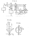
- Fig. 4 shows one embodiment of the present invention.
- a semiconductor laser 101 generates a light having a wavelength ⁇ 1 and its output light beam is indicated by 1.
- a reference numeral 102 denotes a condenser lens for condensing the spreading output light of the semiconductor laser so as to obtain a substantially parallel light beam.
- a numeral 105 represents a light beam synthesizer for allowing the light having a wavelength ⁇ 1 to be transmitted and for reflecting the light having a wavelength ⁇ 2 which will be described later, while numeral 106 denotes a beam spilitter.
- a numeral 107 denotes a reflective mirror. The light beam 1 of the semiconductor laser 101 passes through these optical elements and enters a diaphragm lens 108.
- the diaphragm lens 108 acts to converge the incident light beam 1 to produce substantial circular light spot L on the groove 51 which serves as the guide track.
- a numeral 109 indicates an actuator to drive the diaphragm lens 108.
- This actuator drives the diaphragm lens in the direction of the optical axis in accordance with the surface oscillation of the disc, thereby performing a known focusing control.
- the actuator also drives the diaphragm lens 108 in the direction perpendicular to the incident optical axis and to the guide track to perform a known tracking control against the guide track which inherently has eccentricity. If necessary, the actuator drives the diaphragm lens in the tangential direction of the guide track, thereby to perform the control in the direction of the time base.
- a reference numeral 103 denotes a semiconductor laser for generating a light beam m having a wavelength ⁇ 2
- 104 indicates a condenser lens.
- the light beam m is reflected by the beam synthesizer 105 and passes through the substantially same light passageway as that of the light beam l and enters the diaphragm lens 108, so that a substantially elliptic or hyperelliptic light spot M whose longitudinal direction coincides with the longitudinal direction of the groove 51 is formed on the same groove 51 as in the case of the light spot L.
- the method of formation and its effect of the above-mentioned elliptic light spot M will be described later with reference to Figs. 5a, 5b, 6a, 6b, and 7.
- the light beam reflected by the optical recording disc passes through the diaphragm lens 108 and mirror 107 and enters the beam splitter 106 and then is reflected by the beam splitter 106 and thereafter enters filter plate 111. In this case, only the light having the wavelength X 1 is transmitted, but the light having the wavelength X 2 is not transmitted.
- a single lens 112 converts the reflected light beam 1 into the condensed light.
- a reflective mirror 113 serves to interrupt half of the light condensed by the single lens 112 and serves as a reflective mirror.
- a numeral 114 represents two-split photo diodes for detecting a focusing error signal, these diodes are disposed on the focal point of the single lens 112 and detect a conventionally known focusing error signal in respone to the split light l 1 .
- a numeral 115 shows two-split photo diodes to detect a tracking error signal, these diodes detect a tracking error signal due to the light l2 reflected by the mirror 113.
- the reproduction signals of the signals recorded on the grooves 51 of the disc are obtained by means of the photo detector 114 or 115.
- a circuit 116 drives the laser 103 and controls the intensity of the elliptic light spot M formed on the groove 51.
- a circuit 117 drives the laser 101 and controls the intensity of the light spot L formed on the groove 51.
- An amplifier 120 is a circuit to amplify a signal indicative of the difference between the outputs generated from each element of the split photo diodes 115 and generates the tracking error signal at its terminal TR.
- An amplifier 121 is a circuit to amplify a signal representative of the sum of each output of the photo diodes 115 and outputs the reproduction signal and the like at its terminal PB.
- a reference numeral 122 indicates a circuit to amplify a difference signal between each element of the split photo diodes 114 and this amplifier outputs the focusing error signal at its terminal FD.
- two light spots are closely formed on the same guide track, in which one light spot is substantialy circular and the other light spot is elliptic which extends along the guide track.
- These lights have desired intensities or desired signals and are irradiated on the thin recording film while tracking the guide track of the optical recording disc.
- FIG. 5a shows an example of incident process of the light into the diaphragm lens 108 in the cases where the circular micro light spot L and an elliptic light spot M are formed on the groove 51.
- Fig. 5a shows a process of incidence of the light into the diaphragm lens in the cross section perpendicular to the guide groove 51 and in the tangential direction of the guide groove 51.
- Fig. 5b is a plan view as viewed from the incident surface of the diaphragm lens 108.
- the same elements and components as those in Fig. 4 are designated by the same reference numerals and characters.
- a reference character r l denotes the optical axes of the light beam 1 and the diaphragm lens 108 and r indicates the optical axis of the light beam m.
- the light spots L and M can be formed closely in the locations on the groove 51.
- the light beam l enters the full apertuer of the diaphragm lens 108, thereby to form the substantially circular light spot L on the groove 51.
- the light beam m uses the whole aperture of the diaphragm lens 108 in the direction perpendicular to the grove 51, it uses only part of the aperture of the diaphragm lens 108 in the tangential direction of the grove 51.
- the elliptic light enters, so that it is possible to form the hyperelliptic light spot M which is thin in the direction of the groove width and is long in the tangential direction of the groove on the groove 51.
- An arrow X represents the oscillation direction of the diaphragm lens 108 in the case where the light spots L and M are allowed to track the groove 51.
- Figs. 6a and 6b show an example of the process of forming the elliptic light beam m shown in Fig. 5b.
- the same components as those in Fig. 4 are designated by the same reference numerals.
- the semiconductor laser 103 has different angles of divergence of the light beam with respect to the direction perpendicular (i) to and the direction parallel (//) to the junction surface, these values are determined at the time of designing the junction surface.
- the angle of divergence in the direction parallel to the junction surface is indicates by ⁇ //, while the angle of divergence in the direction perpendicular thereto is represented by ⁇ . Therefore, as shown in the drawings, the light beam having an elliptic light cross-section can be formed by arranging the condenser lens 104 in such a manner that the enter apertuer is used in the direction 1 and only part of the aperture is used in the direction of ⁇ //.
- Fig. 7 illustrates practical examples of the light spots L and M formed closely on the same guide track in the construction of Fig. 4.
- the light spot L is the almost circular micro-lightspot having the wavelength 11 and is used to record and reproduce signals on the guide tracks. This light spot L is also used to detect control signals for the focal control, tracking control, etc.
- the light spot M having a longitudinal diameter in the tangential direction of the guide track has a wavelength different from that of the light spot L and serves as the light spot to erase the signals which have been preliminarily recorded on the tracks without affecting the recording and reproducing of the signals by the light spot L.
- this erasing lightspot M is simply utilized to supply the energy to the disc only when one wishes to erase desired information or for only the interval on the disc on which the information to be erased has been recorded.
- the semiconductor laser 103 of Fig. 4 to produce this erasing light spot M emits only when one wishes to erase and does not need to emit in other cases. That is, only the lightspot L may be used in the ordinary mode of recording and reproducing the signals.
- the lightspot M As described above, it is suitable to supply the lightspot M as the light power which is timely continuous to the thin recording film in the interval where the signals are to be erased to provide the condition for temperaure elevation and slow cooling to the thin recording film.
- Fig. 8 shows an example of the format of the optical recording disc to be used in the present invention.
- a reference character a denotes a center hole and b indicates an information recording area.
- Characters i and i+1 show grooves fored in the information recording area of the disc, in this case they denote the (i)th and (i+l)th grooves (tracks).
- Characters A i , A 2 , ---, A represent areas in which track address signals which are peculiar to each groove and sector address signals have been recorded as pit- like signals, wherein one track (grooves) is divided into a number of sector areas.
- a reference numerals 1, 2, 3, ---, n indicate sector areas, which are the areas to record and reproduce the signals such as the grooves 51 of Fig. 3.
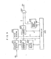
- Fig. 9 shows a practical constructional example in the case where the signals are recorded, reproduced and erased on the disc which has been preliminarily formated in this way.
- the signals recorded on the optical disc are reproduced by the light spot L and output from the terminal PB in the optical recording and reproducing apparatus of Fig. 4, and these signals are outputed to the terminal PB of Fig. 9.
- a reproducing register 201 reads out the track address and the sector addresses A l , A 2' ---, An of the disc shown in Fig. 8 and temporarily stores them, and then outputs the same.
- a controller 200 is constituted by a microcomputer or the like and serves to control each section of the optical recording and reproducing apparatus. Only part of the operations - necessary to explain the present invention will be described here. For example, a case will be described where the signal which has been preliminarily recorded in the second sector of the (i)th track in the format of Fig.
- the controller 200 sets the address A 2i of the second sector of the (i)th track into a setting register 204, and at the same time it sets an erasing mode register 206 and outputs a high-level signal on a line q.
- the light spot L of Fig. 4 hunts the (i)th track of the disc, reads out the address signals A 1i , A 2i , --- on its track, stores its content in the reproducing register 201, and outputs to a coincidence detection circuit 203.
- a sector detection circuit 202 detects a change of the content of the reproducing register 201 and generates a pulse to a line i whenever the light spot L passes through a new sector.
- the controller detects this signal and manages the number of sectors on which the- light spot L passed.
- a 2i is set into the reproducing register 201.
- a coincidense signal is generated to an output line j of the coincidence detection circuit 203.
- This signal serves to set an erasing interval flip flop 205, so that a high-level signal is output to a line p.
- An AND gate 207 generates at its terminal ER an output-signal for allowing the erasing semiconductor laser to emit the light since both lines p and g are at high level.
- the light spot M of fig. 4 is emitted on the basis of this for a necessary period of time.
- the controller 200 receives the coincidence detection signal on the line i, it monitors the number of sectors on which the lightspot on the line i passes. When the lightspot passes a predetermined number of sectors, the controller 200 generates outputs on lines k and R to reset the erasing interval flip-flop 205 and erasing mode register 206, thereby stopping the irradiation by the erasing light. In this manner, as shown in Fig.
- the circular micro-lightspot L and the elliptic lightspot M which is long along the track are formed on the same guide groove (track), and the interval to be erased on the disc is detected and fixed by the circular spot L and the signal recorded in the relevant interval can be erased by the elliptic light spot M.
- the moving direction of the disc and the arrangement of the lightspots L and m are not limited to those shown in this drawing.
- the lightspot L may overlap the light spot M, and the order of L and M may be reversed.
- first and second lightspots which are almost circular and to closely arrange these spots such that they conjointly become a single almost elliptic spot on the same track.
- signals can be recorded and reproduced by the almost circular micro-lightspot, and the signals which have been preliminarily recorded can be erased by the light spot which is elliptic along the guide track or cooperatively by the above-mentioned circular light spot and the above mentioned elliptic light spot: thus, the function of the conventional optical recording and reproducing apparatus of the write-once type can be further raised.
Landscapes
- Physics & Mathematics (AREA)
- Optics & Photonics (AREA)
- Optical Recording Or Reproduction (AREA)
- Optical Head (AREA)
Abstract
Description
- This invention relates to an optical recording and reproducing apparatus and, more particularly, to an optical and reversible recording and reproducing apparatus in which a laser beam is converged to a micro-lightbeam having a diameter of about 1 pm using a lens or the like and this micro-lightbeam is applied onto an optical recording medium to record and reproduce signals with high density and to erase the recorded signals, thereby to permit repetitional recording and reproducing of the signals.
- Conventionally, as one example of optical recording and reproducing apparatus, an apparatus has been proposed and used in which signals are recorded and reproduced with high density by applying a laser beam or the like having the above-mentioned micro-beam diameter on an optical recording disc which is rotating. This kind of optical recording and reproducing apparatus is highlighted as an apparatus which can provide a new recording device and media for future society that will be filled with great amount of information in view of advantages of apparatus of this kind that the recording . density is high and, therefore, the memory cost per one bit can be.reduced, that the access time is very short and that the recording and reproducing can be stably performed since an optical head does not come into contact with the tracks of the optical recording disc.
- As the above-mentioned method of optical recording and reproducing, the write-once type and the erasable type have been proposed. As a write-once type recording and reproducing method, there has been proposed one method of recording and reproducing signals in which the thin recording film is locally evaporated by the thermal energy of the lasers to form small holes, and another method of recording and reproducing signals in which the optical density of the thin recording film is locally changed by the thermal energy of the laser beam, or the like. On the other hand, as an optical recording and reproducing apparatus of the erasable type, there have been proposed a first method in which a magnetic optical recording material is used to record and reproduce signals, in cooperation with the thermal effect of the laser, and an external magnetic field is used, and a second method in which with respect to the thin recording film whose optical density is changed as mentioned above, the optical density is reversibly changed only by using the thermal energy of the laser. It is worth noting that because the optical density can be reversibly changed, signals can be erasably recorded and reproduced on and from an optical recording medium.
- As one proposed method of reversibly varying the density of the thin recording film, a transition between the amorphous state and the crystal state of the thin recording film, or a transition between one amorphous state and another stable amorphous state is repeatedly carried out. Additionally, there is also proposed a method in which a change in size of the crystal partiles in an amorphous matrix is utilized.
- Prior to description, it is assumed that the optical density change is obtained, utilizing a transition between the amorphous state and the crystal state for simplicity of description.
- Fig. 1 shows a simplified model of the condition for transition between the amorphous state and the crystal state.
- In Fig. 1, the amorphous state is indicated by a reference character (A), in which the reflection factor of the light of the thin recording film is small, while the transmission factor of the light is large. The crystal state is represented by (C), in which the reflection factor of the thin recording film is large, but the transmission factor is small. With this thin recording film in which the optical density can be reversibly changed, when the temperatuare of the thin recording film in the amorphous state (A) in Fig. 1 is locally raised up to near its melting point and its portion is slowly cooled, the relevant portion becomes the crystal state (C). On the other hand, when the temperatuer of the thin recording film in the crystal state is locally raised up to near its melting point and its portion is rapidly cooled, the corresponding portion becomes the amorphous state (A).
- Figs. 2a and 2b show examples of method of realizing the condition to raise-the temperature and cool rapidly and the condition to raise the temperature and cool slowly on the thin recording film.
- Fig. 2a shows an almost circular micro spot L to be formed by the laser or the like on the recording medium which relatively moves in the direction indicates by an arrow. When the intensity of this light spot L is enlarged for only a short period of time to raise the temperature of a local portion of the thin film, the thermal energy due to this temperature elevation at this local portion will be rapidly diffused to the thin film and the supporting member of the thin film, thereby providing the rapid cooling condition. In contrast, as shown in Fig. 2b, when an elongated light spot M which extends in the moving direction (indicated by an arrow) of the recording medium is produced in the similar manner as above by the laser and the like on the recording medium and then the intensity of this light spot M is continuously or intermittently enlarged, the relevant portion of the thin recording film is heated over a wide area. Thus, this heated portion will be fairly slowly cooled than in the case of Fig. 2a. That is to say, the condition for temperature elevation and rapid cooling is obtained by applying the circular micro-beam on the thin recording film which relatively moves and time-modulating its intensity, thereby to produce the pulse-like light. On one hand, the condition for temperature elevation- and slow cooling is obtained by applying the light beam which is elongated in the moving direction of the thin recording film on this thin recording film which relatively moves.
- It is an object of the present invention to provide a novel optical and reversible recording and reproducing apparatus for allowing the optical characteristic of a thin optically recording film to be reversibly changed using the thermal phenomenon with the use of the laser beam or the like, in which a first light spot to provide the above-mentioned condition for temperature elevation and rapid cooling and a second light spot to provide the condition for temperature elevation and slow cooling are formed by the same diaphragm lens, wand the both spots are closely arranged on the same guide track in a disc, and in which by controlling the intensities of the both light spots at need, signals can be erasably recorded on and reproduced from the optical recording film.
- A more specific object of the present invention is to provide such a novel apparatus in which a substantially circular light spot, as the above-mentioned first light spot, and an eliptic light spot, as the above-mentioned second sport, having a different wave length from that of the first light elongated along the guide track are closely arranged on the same guide track in the optical disc using the same diaphragm lens, and in which signals can be recorded and reproduced, using the first light spot and the already recorded signals can be erased by providing the condition for temperature elevation and slow cooling for the thin recording film using solely the second light spot or cooperatively using both first and second light spots.
- A further object of the invention is to provide such a novel apparatus in which the format information recorded on the optical recording disc is read out and the interval to be erased on the optical recording disc, i.e. the erasing region is detected and fixed by the first light spot, and in which the erasing light constituted by the second light spot and the like can irradiate on only the specific interval to be read out by the first light spot.
-
- Fig. 1 is a diagram showing one example of the operational principle of an optical recording thin film material which enables the optical density to be reversibly changed;
- Figs. 2a and 2b are diagrams showing the forms of the light beam to be applied onto the thin recording material and the conditon for temperature elevation and rapid cooling and the condition for temperature elevation and show cooling in the thin film;
- Fig. 3 is a diagram illustrating an example of the construction of the optical recording disc having grooves as optical guide tracks to be used in one embodiment of the present invention;
- Fig. 4 shows an entire constructional diagram in one embodiment of the present invention;
- Figs. 5a and 5b are diagrams showing a method of incidence of alight beam into a diaphragm lens when an almost circular micro light spot and an elliptic light spot having a longitudinal diameter in the tangential direction of the guide track are formed on the disc;
- Figs. 6a and 6b are diagrams showing the mutual relation between a semiconductor laser and a condenser lens when forming an elliptic light on the disc;
- Fig. 7 is a diagram showing the mutual functions of the almost circular light beam and elliptical light beam formed on the same guide track;
- Fig. 8 is a schematic diagram showing an example of the optical recording disc which has been preformated; and
- Fig. 9 shows an example of a circuit for controlling the light emission of the erasing light.
- A practical embodiment of an optical and reversible recording and reproducing apparatus according to the invention will be described hereinbelow with reference to the drawings.
- Fig. 3 is a cross sectional view in the radial direction of an optical recording disc ..aving guide tracks (pregrooves disc) to be used for the present invention. In this embodiment, as an example of the guide track, there is shown an optical pregrooves disc having grooves in the entire surface of the signal recording area on the disc.
- In Fig. 3, a
disc substrate 50 is made of a transparent material, on which groves 51 each having a width w, depth d and track pitch p are formed spirally or coaxially. Athin recording film 52 having a thickness t is formed by the metal evaporating process or other process on thedisc substrate 50. Aprotective layer 53 is further formed on thisfilm 52. - Each width w of the
grooves 51 is smaller than the diameter of alaser beam 54 to be irradiated. The depth d of each groove is selected to be such a value that when the center of the optical axis deviates from the center of the groove, the diffraction effects due to the groove in the fir-field pattern of the reflected light become asymmetric with respect to the optical axis. More specifically, when the wavelength of the laser beam to be applied is X, its depth d is set to approximately X/6 to λ/12. - Such grooves serve as guide tracks which-can be optically detected by means of the
laser light 54 applied thereto. Namely, by detecting the asymmetry of the fir-field pattern of the reflected light, a well-known tracking servo can be applied. Therefore, the appliedlight 54 of Fig. 3 can record or reproduce signals along a specific groove. - Although the
grooves 51 shown in Fig. 3 have been described as one example of the guide tracks, other several processes for guiding the recording and reproducing light beam are known as the guide tracks. However, they are omitted here since they are not directly relevant to this invention. - Fig. 4 shows one embodiment of the present invention.
- In Fig. 4, a semiconductor laser 101 generates a light having a wavelength λ1 and its output light beam is indicated by 1. A
reference numeral 102 denotes a condenser lens for condensing the spreading output light of the semiconductor laser so as to obtain a substantially parallel light beam. Anumeral 105 represents a light beam synthesizer for allowing the light having a wavelength λ1 to be transmitted and for reflecting the light having a wavelength À2 which will be described later, whilenumeral 106 denotes a beam spilitter. Anumeral 107 denotes a reflective mirror. The light beam 1 of the semiconductor laser 101 passes through these optical elements and enters adiaphragm lens 108. Thediaphragm lens 108 acts to converge the incident light beam 1 to produce substantial circular light spot L on thegroove 51 which serves as the guide track. A numeral 109 indicates an actuator to drive thediaphragm lens 108. This actuator drives the diaphragm lens in the direction of the optical axis in accordance with the surface oscillation of the disc, thereby performing a known focusing control. The actuator also drives thediaphragm lens 108 in the direction perpendicular to the incident optical axis and to the guide track to perform a known tracking control against the guide track which inherently has eccentricity. If necessary, the actuator drives the diaphragm lens in the tangential direction of the guide track, thereby to perform the control in the direction of the time base. - Referring to Fig. 4 again, a
reference numeral 103 denotes a semiconductor laser for generating a light beam m having a wavelength λ2, and 104 indicates a condenser lens. The light beam m is reflected by thebeam synthesizer 105 and passes through the substantially same light passageway as that of the light beam ℓ and enters thediaphragm lens 108, so that a substantially elliptic or hyperelliptic light spot M whose longitudinal direction coincides with the longitudinal direction of thegroove 51 is formed on thesame groove 51 as in the case of the light spot L. The method of formation and its effect of the above-mentioned elliptic light spot M will be described later with reference to Figs. 5a, 5b, 6a, 6b, and 7. - The light beam reflected by the optical recording disc passes through the
diaphragm lens 108 andmirror 107 and enters thebeam splitter 106 and then is reflected by thebeam splitter 106 and thereafter enters filter plate 111. In this case, only the light having the wavelength X1 is transmitted, but the light having the wavelength X2 is not transmitted. Asingle lens 112 converts the reflected light beam 1 into the condensed light. Areflective mirror 113 serves to interrupt half of the light condensed by thesingle lens 112 and serves as a reflective mirror. A numeral 114 represents two-split photo diodes for detecting a focusing error signal, these diodes are disposed on the focal point of thesingle lens 112 and detect a conventionally known focusing error signal in respone to the split light ℓ1. A numeral 115 shows two-split photo diodes to detect a tracking error signal, these diodes detect a tracking error signal due to the light ℓ2 reflected by themirror 113. The reproduction signals of the signals recorded on thegrooves 51 of the disc are obtained by means of the photo detector 114 or 115. - A circuit 116 drives the
laser 103 and controls the intensity of the elliptic light spot M formed on thegroove 51. - A circuit 117 drives the laser 101 and controls the intensity of the light spot L formed on the
groove 51. - An
amplifier 120 is a circuit to amplify a signal indicative of the difference between the outputs generated from each element of the split photo diodes 115 and generates the tracking error signal at its terminal TR. -Anamplifier 121 is a circuit to amplify a signal representative of the sum of each output of the photo diodes 115 and outputs the reproduction signal and the like at its terminal PB. Areference numeral 122 indicates a circuit to amplify a difference signal between each element of the split photo diodes 114 and this amplifier outputs the focusing error signal at its terminal FD. - With such a construction, two light spots are closely formed on the same guide track, in which one light spot is substantialy circular and the other light spot is elliptic which extends along the guide track. These lights have desired intensities or desired signals and are irradiated on the thin recording film while tracking the guide track of the optical recording disc.
- Referring now to Figs. 5a and 5b, there is shown an example of incident process of the light into the
diaphragm lens 108 in the cases where the circular micro light spot L and an elliptic light spot M are formed on thegroove 51. Fig. 5a shows a process of incidence of the light into the diaphragm lens in the cross section perpendicular to theguide groove 51 and in the tangential direction of theguide groove 51. Fig. 5b is a plan view as viewed from the incident surface of thediaphragm lens 108. The same elements and components as those in Fig. 4 are designated by the same reference numerals and characters. - In Fig. 5a, a reference character r ℓ denotes the optical axes of the light beam 1 and the
diaphragm lens 108 and r indicates the optical axis of the light beam m. As illustrated in the drawings, by slightly inclining the optical axis of the light beam m by an angle 8 with respect to the tangential direction of thegroove 51, the light spots L and M can be formed closely in the locations on thegroove 51. In the plan view of Fig. 5b, the light beam ℓ enters the full apertuer of thediaphragm lens 108, thereby to form the substantially circular light spot L on thegroove 51. To the contrary, although the light beam m uses the whole aperture of thediaphragm lens 108 in the direction perpendicular to thegrove 51, it uses only part of the aperture of thediaphragm lens 108 in the tangential direction of thegrove 51. In this way, the elliptic light enters, so that it is possible to form the hyperelliptic light spot M which is thin in the direction of the groove width and is long in the tangential direction of the groove on thegroove 51. - An arrow X represents the oscillation direction of the
diaphragm lens 108 in the case where the light spots L and M are allowed to track thegroove 51. - Figs. 6a and 6b show an example of the process of forming the elliptic light beam m shown in Fig. 5b. The same components as those in Fig. 4 are designated by the same reference numerals.
- Generally, the
semiconductor laser 103 has different angles of divergence of the light beam with respect to the direction perpendicular (i) to and the direction parallel (//) to the junction surface, these values are determined at the time of designing the junction surface. In Figs. 6a and 6b, the angle of divergence in the direction parallel to the junction surface is indicates by θ//, while the angle of divergence in the direction perpendicular thereto is represented by θ. Therefore, as shown in the drawings, the light beam having an elliptic light cross-section can be formed by arranging thecondenser lens 104 in such a manner that the enter apertuer is used in the direction 1 and only part of the aperture is used in the direction of θ//. - Fig. 7 illustrates practical examples of the light spots L and M formed closely on the same guide track in the construction of Fig. 4.
- The light spot L is the almost circular micro-lightspot having the wavelength 11 and is used to record and reproduce signals on the guide tracks. This light spot L is also used to detect control signals for the focal control, tracking control, etc. On the other hand, the light spot M having a longitudinal diameter in the tangential direction of the guide track has a wavelength different from that of the light spot L and serves as the light spot to erase the signals which have been preliminarily recorded on the tracks without affecting the recording and reproducing of the signals by the light spot L. Namely, this erasing lightspot M is simply utilized to supply the energy to the disc only when one wishes to erase desired information or for only the interval on the disc on which the information to be erased has been recorded. Thus, the
semiconductor laser 103 of Fig. 4 to produce this erasing light spot M emits only when one wishes to erase and does not need to emit in other cases. That is, only the lightspot L may be used in the ordinary mode of recording and reproducing the signals. - To erase the signals which have been prerecorded using the lightspot M, as described above, it is suitable to supply the lightspot M as the light power which is timely continuous to the thin recording film in the interval where the signals are to be erased to provide the condition for temperaure elevation and slow cooling to the thin recording film.
- Fig. 8 shows an example of the format of the optical recording disc to be used in the present invention. In Fig. 8, a reference character a denotes a center hole and b indicates an information recording area. Characters i and i+1 show grooves fored in the information recording area of the disc, in this case they denote the (i)th and (i+l)th grooves (tracks). Characters Ai, A2, ---, A represent areas in which track address signals which are peculiar to each groove and sector address signals have been recorded as pit- like signals, wherein one track (grooves) is divided into a number of sector areas. A
reference numerals grooves 51 of Fig. 3. Fig. 9 shows a practical constructional example in the case where the signals are recorded, reproduced and erased on the disc which has been preliminarily formated in this way. - In Fig. 9, the signals recorded on the optical disc are reproduced by the light spot L and output from the terminal PB in the optical recording and reproducing apparatus of Fig. 4, and these signals are outputed to the terminal PB of Fig. 9. A reproducing
register 201 reads out the track address and the sector addresses Al, A2' ---, An of the disc shown in Fig. 8 and temporarily stores them, and then outputs the same. Acontroller 200 is constituted by a microcomputer or the like and serves to control each section of the optical recording and reproducing apparatus. Only part of the operations - necessary to explain the present invention will be described here. For example, a case will be described where the signal which has been preliminarily recorded in the second sector of the (i)th track in the format of Fig. 8 is to be erased by the recording and reproducing apparatus. Firstly, thecontroller 200 sets the address A2i of the second sector of the (i)th track into asetting register 204, and at the same time it sets an erasingmode register 206 and outputs a high-level signal on a line q. In response to this signal, the light spot L of Fig. 4 hunts the (i)th track of the disc, reads out the address signals A1i, A2i, --- on its track, stores its content in the reproducingregister 201, and outputs to acoincidence detection circuit 203. Asector detection circuit 202 detects a change of the content of the reproducingregister 201 and generates a pulse to a line i whenever the light spot L passes through a new sector. The controller detects this signal and manages the number of sectors on which the- light spot L passed. When the light spot 1 passes on the (i)th track A2i of Fig. 8, A2i is set into the reproducingregister 201. At this time a coincidense signal is generated to an output line j of thecoincidence detection circuit 203. This signal serves to set an erasinginterval flip flop 205, so that a high-level signal is output to a line p. An ANDgate 207 generates at its terminal ER an output-signal for allowing the erasing semiconductor laser to emit the light since both lines p and g are at high level. The light spot M of fig. 4 is emitted on the basis of this for a necessary period of time. When thecontroller 200 receives the coincidence detection signal on the line i, it monitors the number of sectors on which the lightspot on the line i passes. When the lightspot passes a predetermined number of sectors, thecontroller 200 generates outputs on lines k and R to reset the erasing interval flip-flop 205 and erasingmode register 206, thereby stopping the irradiation by the erasing light. In this manner, as shown in Fig. 4, the circular micro-lightspot L and the elliptic lightspot M which is long along the track are formed on the same guide groove (track), and the interval to be erased on the disc is detected and fixed by the circular spot L and the signal recorded in the relevant interval can be erased by the elliptic light spot M. In Fig. 7, the moving direction of the disc and the arrangement of the lightspots L and m are not limited to those shown in this drawing. For example, the lightspot L may overlap the light spot M, and the order of L and M may be reversed. These problems can be solved as the problem of the timing of detecting the coincidence and the timing of emitting the erasing light in Fig. 9, and as the problem of the data format to be recorded on the disc. In addition, it is possible to make the condition for temperature elevation and slow cooling which is broader than in the cases where only the lightspot M is emitted if the intensity of the lightspot L is enlarged more than the intensity of the reproducing light by the signal at the terminal ER of Fig. 9 and at the same time the lightspot M is also emitted. - Namely, it may be possible to use the first and second lightspots which are almost circular and to closely arrange these spots such that they conjointly become a single almost elliptic spot on the same track.
- As described above, according to the presetn invention, signals can be recorded and reproduced by the almost circular micro-lightspot, and the signals which have been preliminarily recorded can be erased by the light spot which is elliptic along the guide track or cooperatively by the above-mentioned circular light spot and the above mentioned elliptic light spot: thus, the function of the conventional optical recording and reproducing apparatus of the write-once type can be further raised.
Claims (5)
Applications Claiming Priority (2)
| Application Number | Priority Date | Filing Date | Title |
|---|---|---|---|
| JP179086/82 | 1982-10-14 | ||
| JP57179086A JPS5968844A (en) | 1982-10-14 | 1982-10-14 | Optical reversible recording and reproducing device |
Publications (3)
| Publication Number | Publication Date |
|---|---|
| EP0106673A2 true EP0106673A2 (en) | 1984-04-25 |
| EP0106673A3 EP0106673A3 (en) | 1984-05-30 |
| EP0106673B1 EP0106673B1 (en) | 1991-01-02 |
Family
ID=16059828
Family Applications (1)
| Application Number | Title | Priority Date | Filing Date |
|---|---|---|---|
| EP83306198A Expired - Lifetime EP0106673B1 (en) | 1982-10-14 | 1983-10-13 | Optical and reversible recording and reproducing apparatus |
Country Status (4)
| Country | Link |
|---|---|
| US (1) | US4566088A (en) |
| EP (1) | EP0106673B1 (en) |
| JP (1) | JPS5968844A (en) |
| DE (1) | DE3382075D1 (en) |
Cited By (12)
| Publication number | Priority date | Publication date | Assignee | Title |
|---|---|---|---|---|
| DE3504968A1 (en) * | 1984-02-13 | 1985-08-14 | Pioneer Electronic Corp., Tokio/Tokyo | RECORDING DEVICE FOR AN OPTICAL DISK |
| DE3510519A1 (en) * | 1984-03-22 | 1985-09-26 | Kabushiki Kaisha Toshiba, Kawasaki, Kanagawa | OPTICAL SYSTEM FOR TRACKING A INFORMATION RECORDER |
| EP0162702A1 (en) * | 1984-05-23 | 1985-11-27 | Sony Corporation | Tracking control arrangements for use in optical disc players |
| EP0163421A1 (en) * | 1984-04-27 | 1985-12-04 | Matsushita Electric Industrial Co., Ltd. | Method for recording and erasing optical information |
| EP0164745A2 (en) * | 1984-06-13 | 1985-12-18 | Hitachi, Ltd. | Method of and apparatus for recording/erasing information by utilizing light induced thermo-magnetic effect |
| EP0187664A2 (en) * | 1985-01-09 | 1986-07-16 | Victor Company Of Japan, Limited | Optical arrangement for forming an elongated laser beam spot on erasable optical disks |
| DE3601265A1 (en) * | 1985-01-18 | 1986-07-24 | Kabushiki Kaisha Toshiba, Kawasaki, Kanagawa | OPTICAL INFORMATION RECORDING SYSTEM |
| FR2584223A1 (en) * | 1985-06-28 | 1987-01-02 | Thomson Alcatel Gigadisc | OPTICAL MEMORY FOLLOWING SAMPLE TRACK FOR PREGRAVE INFORMATION SUPPORT. |
| EP0223057A2 (en) * | 1985-10-16 | 1987-05-27 | Hitachi, Ltd. | An optical recording method and an apparatus using the method |
| EP0280548A2 (en) * | 1987-02-27 | 1988-08-31 | Matsushita Electric Industrial Co., Ltd. | Erasable optical disk and optical information recording/reproduction apparatus |
| EP0735527A1 (en) * | 1995-03-27 | 1996-10-02 | Matsushita Electric Industrial Co., Ltd. | Super-resolution optical head apparatus |
| CN112562744A (en) * | 2020-07-03 | 2021-03-26 | 暨南大学 | Double-pulse excitation method for ultrafast and super-resolution full photomagnetic recording |
Families Citing this family (36)
| Publication number | Priority date | Publication date | Assignee | Title |
|---|---|---|---|---|
| JPS5936338A (en) * | 1982-08-24 | 1984-02-28 | Matsushita Electric Ind Co Ltd | Optical disk recording and reproducing method |
| JPS605441A (en) * | 1983-06-23 | 1985-01-12 | Canon Inc | Information processor |
| DE3472322D1 (en) * | 1983-08-26 | 1988-07-28 | Hitachi Ltd | Optical information recording and reproducing apparatus |
| NL8402943A (en) * | 1983-09-29 | 1985-04-16 | Toshiba Kk | OPTICAL HEAD. |
| EP0147620B1 (en) * | 1983-11-22 | 1991-06-05 | Kabushiki Kaisha Toshiba | Optical head |
| US4985881A (en) * | 1983-12-23 | 1991-01-15 | Hitachi, Ltd. | Record carrier for a magneto-optical disc memory having guide grooves of a plurality of tracks disposed with a predetermined relation to light spot diameter |
| JPS60236137A (en) * | 1984-05-08 | 1985-11-22 | Nippon Kogaku Kk <Nikon> | Simultaneously erasing-recording type photomagnetic recording system and recording device and medium used for this system |
| JPS60258733A (en) * | 1984-06-05 | 1985-12-20 | Matsushita Electric Ind Co Ltd | Erasable optical recording and reproducing device |
| JPS60261043A (en) * | 1984-06-07 | 1985-12-24 | Victor Co Of Japan Ltd | Information recording medium disc |
| US4679184A (en) * | 1984-06-08 | 1987-07-07 | Matsushita Electric Industrial Co., Ltd. | Optical recording and reproducing apparatus having erasing beam spot with asymmetrical intensity distribution |
| US4700336A (en) * | 1984-06-19 | 1987-10-13 | Matsushita Electric Industrial Co., Ltd. | Optical recording and playback apparatus using plural light spots |
| US4718053A (en) * | 1984-11-09 | 1988-01-05 | Hitachi, Ltd. | Optical information apparatus and method of recording and erasing information |
| DE3546599C2 (en) * | 1984-11-20 | 1993-06-03 | Olympus Optical Co., Ltd., Tokio/Tokyo, Jp | |
| JPS61133052A (en) * | 1984-12-03 | 1986-06-20 | Hitachi Ltd | Optical recording and reproducing device |
| US5062009A (en) * | 1985-03-19 | 1991-10-29 | Canon Kabushiki Kaisha | Recording and/or reproducing apparatus having, in addition to a recording medium, memory means for memorizing information reproduced from the recording medium |
| JPS61233468A (en) * | 1985-04-08 | 1986-10-17 | Hitachi Ltd | Controlling system for writing information in rotary type information recording medium |
| US4949329A (en) * | 1985-05-21 | 1990-08-14 | Hoechst Celanese Corp. | Method of effecting erasure of optical information media including varying duty cycle, laser power and focus offset |
| JPS6284435A (en) * | 1985-10-08 | 1987-04-17 | Matsushita Electric Ind Co Ltd | Information recording and reproducing device |
| US5161243A (en) * | 1986-01-21 | 1992-11-03 | Matsushita Electric Industrial Co., Ltd. | Tracking system for an optical recording/reproducing apparatus having a plurality of light spots |
| JPS62267926A (en) * | 1986-05-16 | 1987-11-20 | Matsushita Electric Ind Co Ltd | Erasable optical disk device |
| US4845696A (en) * | 1986-07-02 | 1989-07-04 | Sony Corporation | Apparatus for optically recording and reproducing information in record tracks on a rotatable record disk |
| US4797871A (en) * | 1986-09-15 | 1989-01-10 | Eastman Kodak Company | Erasable optical recording method |
| EP0261608A3 (en) * | 1986-09-20 | 1990-05-30 | Csk Corporation | Optical recording medium |
| US5014252A (en) * | 1986-10-08 | 1991-05-07 | Nikon Corporation | Over write capable magnetooptical recording method using two beams, and magnetooptical recording apparatus therefor |
| JPS63155436A (en) * | 1986-12-19 | 1988-06-28 | Toshiba Corp | Information recording medium |
| US5214635A (en) * | 1987-02-27 | 1993-05-25 | Matsushita Electric Industrial Co., Ltd. | Erasable optical disk and optical information recording/reproduction apparatus |
| US4785167A (en) * | 1987-08-26 | 1988-11-15 | International Business Machines Corporation | Photodetector having cascaded photoelements |
| EP0318200B1 (en) * | 1987-11-25 | 1994-03-09 | Matsushita Electric Industrial Co., Ltd. | Optical information recording and erasing method |
| JP2839498B2 (en) * | 1988-02-03 | 1998-12-16 | 株式会社日立製作所 | Optical disk media |
| US4991158A (en) * | 1988-03-11 | 1991-02-05 | Mitsubishi Denki Kabushiki Kaisha | Optical information recording and reproducing apparatus |
| US5204847A (en) * | 1989-11-20 | 1993-04-20 | International Business Machines Corporation | Sensing previously-recorded information while recording or erasing a magnetooptic storage number |
| JPH04259921A (en) * | 1991-02-15 | 1992-09-16 | Ricoh Co Ltd | Optical disk device |
| JPH07326066A (en) * | 1994-05-31 | 1995-12-12 | Asahi Optical Co Ltd | Optical information recording and reproducing device |
| EP0831472B1 (en) * | 1996-03-11 | 2003-09-03 | Seiko Epson Corporation | Optical pickup and optical recording apparatus |
| JP2001155346A (en) * | 1999-11-26 | 2001-06-08 | Toshiba Corp | Information recording medium, device and method, information reproducing device and method |
| KR100813942B1 (en) * | 2000-12-07 | 2008-03-14 | 삼성전자주식회사 | Method for high rate optical recording and apparatus thereof |
Citations (10)
| Publication number | Priority date | Publication date | Assignee | Title |
|---|---|---|---|---|
| JPS5250702A (en) * | 1975-10-21 | 1977-04-23 | Matsushita Electric Ind Co Ltd | Optical information recording and reproduction apparatus |
| JPS5285412A (en) * | 1976-01-09 | 1977-07-15 | Matsushita Electric Ind Co Ltd | Optical record regenerative device |
| JPS52149927A (en) * | 1976-06-09 | 1977-12-13 | Mitsubishi Electric Corp | Beam addressable information memory unit |
| JPS54103004A (en) * | 1978-01-30 | 1979-08-14 | Matsushita Electric Ind Co Ltd | Optically recording and reproducing apparatus |
| FR2482756A1 (en) * | 1980-05-14 | 1981-11-20 | Rca Corp | DISC CONTAINING INFORMATION AND METHOD FOR REVERSIVELY RECORDING AND DELETING INFORMATION THEREOF |
| JPS56153540A (en) * | 1980-04-23 | 1981-11-27 | Matsushita Electric Ind Co Ltd | Optical disc device |
| JPS56163528A (en) * | 1980-05-19 | 1981-12-16 | Matsushita Electric Ind Co Ltd | Recording and erasing method of optical information |
| JPS57152549A (en) * | 1981-03-17 | 1982-09-20 | Fujitsu Ltd | Optical recorder |
| GB2095887A (en) * | 1981-03-28 | 1982-10-06 | Kokusai Denshin Denwa Co Ltd | Magneto-optical recording and reproducing system |
| FR2521760A1 (en) * | 1982-02-12 | 1983-08-19 | Thomson Csf | Thermo-optical recording process for video disc - uses two lasers of different wavelengths, only one being intensity modulated |
Family Cites Families (2)
| Publication number | Priority date | Publication date | Assignee | Title |
|---|---|---|---|---|
| US4264986A (en) * | 1979-03-12 | 1981-04-28 | Willis Craig I | Information-recording process & apparatus |
| US4383261A (en) * | 1980-08-21 | 1983-05-10 | The United States Of America As Represented By The Director Of The National Security Agency | Method for laser recording utilizing dynamic preheating |
-
1982
- 1982-10-14 JP JP57179086A patent/JPS5968844A/en active Pending
-
1983
- 1983-10-12 US US06/542,014 patent/US4566088A/en not_active Expired - Fee Related
- 1983-10-13 DE DE8383306198T patent/DE3382075D1/en not_active Expired - Lifetime
- 1983-10-13 EP EP83306198A patent/EP0106673B1/en not_active Expired - Lifetime
Patent Citations (10)
| Publication number | Priority date | Publication date | Assignee | Title |
|---|---|---|---|---|
| JPS5250702A (en) * | 1975-10-21 | 1977-04-23 | Matsushita Electric Ind Co Ltd | Optical information recording and reproduction apparatus |
| JPS5285412A (en) * | 1976-01-09 | 1977-07-15 | Matsushita Electric Ind Co Ltd | Optical record regenerative device |
| JPS52149927A (en) * | 1976-06-09 | 1977-12-13 | Mitsubishi Electric Corp | Beam addressable information memory unit |
| JPS54103004A (en) * | 1978-01-30 | 1979-08-14 | Matsushita Electric Ind Co Ltd | Optically recording and reproducing apparatus |
| JPS56153540A (en) * | 1980-04-23 | 1981-11-27 | Matsushita Electric Ind Co Ltd | Optical disc device |
| FR2482756A1 (en) * | 1980-05-14 | 1981-11-20 | Rca Corp | DISC CONTAINING INFORMATION AND METHOD FOR REVERSIVELY RECORDING AND DELETING INFORMATION THEREOF |
| JPS56163528A (en) * | 1980-05-19 | 1981-12-16 | Matsushita Electric Ind Co Ltd | Recording and erasing method of optical information |
| JPS57152549A (en) * | 1981-03-17 | 1982-09-20 | Fujitsu Ltd | Optical recorder |
| GB2095887A (en) * | 1981-03-28 | 1982-10-06 | Kokusai Denshin Denwa Co Ltd | Magneto-optical recording and reproducing system |
| FR2521760A1 (en) * | 1982-02-12 | 1983-08-19 | Thomson Csf | Thermo-optical recording process for video disc - uses two lasers of different wavelengths, only one being intensity modulated |
Non-Patent Citations (7)
| Title |
|---|
| PATENTS ABSTRACTS OF JAPAN, vol. 1, no. 119, 11th October 1977, page 4470 E 77 & JP - A - 52 50 702 (MATSUSHITA DENKI SANGYO K.K.) 23-04-1977 * |
| PATENTS ABSTRACTS OF JAPAN, vol. 1, no. 146, 26th November 1977, page 7442 E 77 & JP - A - 52 85 412 (MATSUSHITA DENKI SANGYO K.K.) 15-07-1977 * |
| PATENTS ABSTRACTS OF JAPAN, vol. 1, no. 29, 23rd February 1978, page 12097 E 77 & JP - A - 52 149 927 (MITSUBISHI DENKI K.K.) 13-12-1977 * |
| PATENTS ABSTRACTS OF JAPAN, vol. 6, no. 255 (P-162)[1133], 14th December 1982 & JP - A - 57 152 549 (FUJITSU K.K.) 20-09-1982 (Cat. A) * |
| PATENTS ABSTRACTS OF JAPAN, vol. 6, no. 34 (P-104)[912], 2nd March 1982 & JP - A - 56 153 540 (MATSUSHITA DENKI SANGYO K.K.) 27-11-1981 * |
| PATENTS ABSTRACTS OF JAPAN, vol. 6, no. 46 (P-107)[924] 24th March 1982 & JP - A - 56 163 528 (MATSUSHITA DENKI SANGYO K.K.) 16-12-1981 * |
| PATENTS ABSTRACTS OF JAPAN; vol. 3, no. 125(E-145), 19th October 1979, page 92 E 145 & JP - A - 54 103 004 (MATSUSHITA DENKI SANGYO K.K.) 14-08-1979 * |
Cited By (20)
| Publication number | Priority date | Publication date | Assignee | Title |
|---|---|---|---|---|
| DE3504968A1 (en) * | 1984-02-13 | 1985-08-14 | Pioneer Electronic Corp., Tokio/Tokyo | RECORDING DEVICE FOR AN OPTICAL DISK |
| DE3510519A1 (en) * | 1984-03-22 | 1985-09-26 | Kabushiki Kaisha Toshiba, Kawasaki, Kanagawa | OPTICAL SYSTEM FOR TRACKING A INFORMATION RECORDER |
| EP0163421A1 (en) * | 1984-04-27 | 1985-12-04 | Matsushita Electric Industrial Co., Ltd. | Method for recording and erasing optical information |
| EP0162702A1 (en) * | 1984-05-23 | 1985-11-27 | Sony Corporation | Tracking control arrangements for use in optical disc players |
| EP0164745A2 (en) * | 1984-06-13 | 1985-12-18 | Hitachi, Ltd. | Method of and apparatus for recording/erasing information by utilizing light induced thermo-magnetic effect |
| EP0164745A3 (en) * | 1984-06-13 | 1988-03-30 | Hitachi, Ltd. | Method of and apparatus for recording/erasing information by utilizing light induced thermo-magnetic effect |
| EP0187664A3 (en) * | 1985-01-09 | 1988-02-24 | Victor Company Of Japan, Limited | Optical arrangement for forming an elongated laser beam spot on erasable optical disks |
| EP0187664A2 (en) * | 1985-01-09 | 1986-07-16 | Victor Company Of Japan, Limited | Optical arrangement for forming an elongated laser beam spot on erasable optical disks |
| DE3601265A1 (en) * | 1985-01-18 | 1986-07-24 | Kabushiki Kaisha Toshiba, Kawasaki, Kanagawa | OPTICAL INFORMATION RECORDING SYSTEM |
| EP0208212A1 (en) * | 1985-06-28 | 1987-01-14 | Thomson S.A. | Optical memory with sampled tracking for a pregrooved record carrier |
| FR2584223A1 (en) * | 1985-06-28 | 1987-01-02 | Thomson Alcatel Gigadisc | OPTICAL MEMORY FOLLOWING SAMPLE TRACK FOR PREGRAVE INFORMATION SUPPORT. |
| EP0223057A3 (en) * | 1985-10-16 | 1988-10-05 | Hitachi, Ltd. | An optical recording method and an apparatus using the method |
| EP0223057A2 (en) * | 1985-10-16 | 1987-05-27 | Hitachi, Ltd. | An optical recording method and an apparatus using the method |
| EP0280548A2 (en) * | 1987-02-27 | 1988-08-31 | Matsushita Electric Industrial Co., Ltd. | Erasable optical disk and optical information recording/reproduction apparatus |
| EP0280548A3 (en) * | 1987-02-27 | 1990-07-25 | Matsushita Electric Industrial Co., Ltd. | Erasable optical disk and optical information recording/reproduction apparatus |
| EP0735527A1 (en) * | 1995-03-27 | 1996-10-02 | Matsushita Electric Industrial Co., Ltd. | Super-resolution optical head apparatus |
| US6115345A (en) * | 1995-03-27 | 2000-09-05 | Matsushita Electric Industrial Co., Ltd. | Super-resolution optical head apparatus |
| US6185168B1 (en) | 1995-03-27 | 2001-02-06 | Matsushita Electric Industrial Co., Ltd. | Super-resolution optical head apparatus |
| CN112562744A (en) * | 2020-07-03 | 2021-03-26 | 暨南大学 | Double-pulse excitation method for ultrafast and super-resolution full photomagnetic recording |
| CN112562744B (en) * | 2020-07-03 | 2021-09-03 | 暨南大学 | Double-pulse excitation method for ultrafast and super-resolution full photomagnetic recording |
Also Published As
| Publication number | Publication date |
|---|---|
| DE3382075D1 (en) | 1991-02-07 |
| US4566088A (en) | 1986-01-21 |
| EP0106673A3 (en) | 1984-05-30 |
| EP0106673B1 (en) | 1991-01-02 |
| JPS5968844A (en) | 1984-04-18 |
Similar Documents
| Publication | Publication Date | Title |
|---|---|---|
| US4566088A (en) | Optical and reversible recording and reproducing apparatus | |
| US4403318A (en) | Apparatus and method for recording, reproducing and erasing on optical recording discs | |
| KR910000332B1 (en) | Recording method of optical information | |
| JPH0777025B2 (en) | Optical recording / reproducing device | |
| US4679184A (en) | Optical recording and reproducing apparatus having erasing beam spot with asymmetrical intensity distribution | |
| US5381395A (en) | Information detection of a phase-change type optical recording medium by shifting the phase of a reference light | |
| JPH0532811B2 (en) | ||
| US7072269B2 (en) | Method for recording information in optical information medium and reproducing information therefrom | |
| US4970711A (en) | Bulk eraser for optical memory media | |
| JPH0816987B2 (en) | Optical recording / reproducing device | |
| JPH02177131A (en) | Method and device for erasing/recording of optical recording medium | |
| JPS5971143A (en) | Optical recorder and reproducer | |
| JPH01154584A (en) | Array laser | |
| JPS60258733A (en) | Erasable optical recording and reproducing device | |
| JPS60197935A (en) | Erasable optical recording and reproducing device | |
| JPS59172167A (en) | Reversible optical recorder and reproducing device | |
| JPS61187139A (en) | Optical information recording method | |
| JPS61239427A (en) | Rewritable optical disk device | |
| JPS618739A (en) | Erasable optical recording and reproducing device | |
| JPS6113454A (en) | Optical recording and reproducing device | |
| JPH0532812B2 (en) | ||
| JPS60263351A (en) | Erasable optical recording and reproducing device | |
| JPS615446A (en) | Erasable optical recording and reproducing device | |
| JPS61133051A (en) | Optical disk memory device | |
| JPS61287055A (en) | Optical recording and reproducing device |
Legal Events
| Date | Code | Title | Description |
|---|---|---|---|
| PUAI | Public reference made under article 153(3) epc to a published international application that has entered the european phase |
Free format text: ORIGINAL CODE: 0009012 |
|
| PUAL | Search report despatched |
Free format text: ORIGINAL CODE: 0009013 |
|
| AK | Designated contracting states |
Designated state(s): DE FR GB |
|
| AK | Designated contracting states |
Designated state(s): DE FR GB |
|
| 17P | Request for examination filed |
Effective date: 19840820 |
|
| GRAA | (expected) grant |
Free format text: ORIGINAL CODE: 0009210 |
|
| AK | Designated contracting states |
Kind code of ref document: B1 Designated state(s): DE FR GB |
|
| REF | Corresponds to: |
Ref document number: 3382075 Country of ref document: DE Date of ref document: 19910207 |
|
| ET | Fr: translation filed | ||
| PG25 | Lapsed in a contracting state [announced via postgrant information from national office to epo] |
Ref country code: GB Effective date: 19911013 |
|
| PLBE | No opposition filed within time limit |
Free format text: ORIGINAL CODE: 0009261 |
|
| STAA | Information on the status of an ep patent application or granted ep patent |
Free format text: STATUS: NO OPPOSITION FILED WITHIN TIME LIMIT |
|
| 26N | No opposition filed | ||
| GBPC | Gb: european patent ceased through non-payment of renewal fee | ||
| PGFP | Annual fee paid to national office [announced via postgrant information from national office to epo] |
Ref country code: FR Payment date: 19931011 Year of fee payment: 11 Ref country code: DE Payment date: 19931011 Year of fee payment: 11 |
|
| PG25 | Lapsed in a contracting state [announced via postgrant information from national office to epo] |
Ref country code: FR Effective date: 19950630 |
|
| PG25 | Lapsed in a contracting state [announced via postgrant information from national office to epo] |
Ref country code: DE Effective date: 19950701 |
|
| REG | Reference to a national code |
Ref country code: FR Ref legal event code: ST |