EP0164745A2 - Method of and apparatus for recording/erasing information by utilizing light induced thermo-magnetic effect - Google Patents
Method of and apparatus for recording/erasing information by utilizing light induced thermo-magnetic effect Download PDFInfo
- Publication number
- EP0164745A2 EP0164745A2 EP85107258A EP85107258A EP0164745A2 EP 0164745 A2 EP0164745 A2 EP 0164745A2 EP 85107258 A EP85107258 A EP 85107258A EP 85107258 A EP85107258 A EP 85107258A EP 0164745 A2 EP0164745 A2 EP 0164745A2
- Authority
- EP
- European Patent Office
- Prior art keywords
- recording
- sector
- erasing
- magnetic field
- recording film
- Prior art date
- Legal status (The legal status is an assumption and is not a legal conclusion. Google has not performed a legal analysis and makes no representation as to the accuracy of the status listed.)
- Granted
Links
Images


Classifications
-
- G—PHYSICS
- G11—INFORMATION STORAGE
- G11B—INFORMATION STORAGE BASED ON RELATIVE MOVEMENT BETWEEN RECORD CARRIER AND TRANSDUCER
- G11B13/00—Recording simultaneously or selectively by methods covered by different main groups among G11B3/00, G11B5/00, G11B7/00 and G11B9/00; Record carriers therefor not otherwise provided for; Reproducing therefrom not otherwise provided for
- G11B13/04—Recording simultaneously or selectively by methods covered by different main groups among G11B3/00, G11B5/00, G11B7/00 and G11B9/00; Record carriers therefor not otherwise provided for; Reproducing therefrom not otherwise provided for magnetically or by magnetisation and optically or by radiation, for changing or sensing optical properties
-
- G—PHYSICS
- G11—INFORMATION STORAGE
- G11B—INFORMATION STORAGE BASED ON RELATIVE MOVEMENT BETWEEN RECORD CARRIER AND TRANSDUCER
- G11B11/00—Recording on or reproducing from the same record carrier wherein for these two operations the methods are covered by different main groups of groups G11B3/00 - G11B7/00 or by different subgroups of group G11B9/00; Record carriers therefor
- G11B11/10—Recording on or reproducing from the same record carrier wherein for these two operations the methods are covered by different main groups of groups G11B3/00 - G11B7/00 or by different subgroups of group G11B9/00; Record carriers therefor using recording by magnetic means or other means for magnetisation or demagnetisation of a record carrier, e.g. light induced spin magnetisation; Demagnetisation by thermal or stress means in the presence or not of an orienting magnetic field
- G11B11/105—Recording on or reproducing from the same record carrier wherein for these two operations the methods are covered by different main groups of groups G11B3/00 - G11B7/00 or by different subgroups of group G11B9/00; Record carriers therefor using recording by magnetic means or other means for magnetisation or demagnetisation of a record carrier, e.g. light induced spin magnetisation; Demagnetisation by thermal or stress means in the presence or not of an orienting magnetic field using a beam of light or a magnetic field for recording by change of magnetisation and a beam of light for reproducing, i.e. magneto-optical, e.g. light-induced thermomagnetic recording, spin magnetisation recording, Kerr or Faraday effect reproducing
- G11B11/10595—Control of operating function
-
- G—PHYSICS
- G11—INFORMATION STORAGE
- G11B—INFORMATION STORAGE BASED ON RELATIVE MOVEMENT BETWEEN RECORD CARRIER AND TRANSDUCER
- G11B11/00—Recording on or reproducing from the same record carrier wherein for these two operations the methods are covered by different main groups of groups G11B3/00 - G11B7/00 or by different subgroups of group G11B9/00; Record carriers therefor
- G11B11/10—Recording on or reproducing from the same record carrier wherein for these two operations the methods are covered by different main groups of groups G11B3/00 - G11B7/00 or by different subgroups of group G11B9/00; Record carriers therefor using recording by magnetic means or other means for magnetisation or demagnetisation of a record carrier, e.g. light induced spin magnetisation; Demagnetisation by thermal or stress means in the presence or not of an orienting magnetic field
- G11B11/105—Recording on or reproducing from the same record carrier wherein for these two operations the methods are covered by different main groups of groups G11B3/00 - G11B7/00 or by different subgroups of group G11B9/00; Record carriers therefor using recording by magnetic means or other means for magnetisation or demagnetisation of a record carrier, e.g. light induced spin magnetisation; Demagnetisation by thermal or stress means in the presence or not of an orienting magnetic field using a beam of light or a magnetic field for recording by change of magnetisation and a beam of light for reproducing, i.e. magneto-optical, e.g. light-induced thermomagnetic recording, spin magnetisation recording, Kerr or Faraday effect reproducing
- G11B11/10502—Recording on or reproducing from the same record carrier wherein for these two operations the methods are covered by different main groups of groups G11B3/00 - G11B7/00 or by different subgroups of group G11B9/00; Record carriers therefor using recording by magnetic means or other means for magnetisation or demagnetisation of a record carrier, e.g. light induced spin magnetisation; Demagnetisation by thermal or stress means in the presence or not of an orienting magnetic field using a beam of light or a magnetic field for recording by change of magnetisation and a beam of light for reproducing, i.e. magneto-optical, e.g. light-induced thermomagnetic recording, spin magnetisation recording, Kerr or Faraday effect reproducing characterised by the transducing operation to be executed
- G11B11/10504—Recording
- G11B11/10506—Recording by modulating only the light beam of the transducer
-
- G—PHYSICS
- G11—INFORMATION STORAGE
- G11B—INFORMATION STORAGE BASED ON RELATIVE MOVEMENT BETWEEN RECORD CARRIER AND TRANSDUCER
- G11B11/00—Recording on or reproducing from the same record carrier wherein for these two operations the methods are covered by different main groups of groups G11B3/00 - G11B7/00 or by different subgroups of group G11B9/00; Record carriers therefor
- G11B11/10—Recording on or reproducing from the same record carrier wherein for these two operations the methods are covered by different main groups of groups G11B3/00 - G11B7/00 or by different subgroups of group G11B9/00; Record carriers therefor using recording by magnetic means or other means for magnetisation or demagnetisation of a record carrier, e.g. light induced spin magnetisation; Demagnetisation by thermal or stress means in the presence or not of an orienting magnetic field
- G11B11/105—Recording on or reproducing from the same record carrier wherein for these two operations the methods are covered by different main groups of groups G11B3/00 - G11B7/00 or by different subgroups of group G11B9/00; Record carriers therefor using recording by magnetic means or other means for magnetisation or demagnetisation of a record carrier, e.g. light induced spin magnetisation; Demagnetisation by thermal or stress means in the presence or not of an orienting magnetic field using a beam of light or a magnetic field for recording by change of magnetisation and a beam of light for reproducing, i.e. magneto-optical, e.g. light-induced thermomagnetic recording, spin magnetisation recording, Kerr or Faraday effect reproducing
- G11B11/10502—Recording on or reproducing from the same record carrier wherein for these two operations the methods are covered by different main groups of groups G11B3/00 - G11B7/00 or by different subgroups of group G11B9/00; Record carriers therefor using recording by magnetic means or other means for magnetisation or demagnetisation of a record carrier, e.g. light induced spin magnetisation; Demagnetisation by thermal or stress means in the presence or not of an orienting magnetic field using a beam of light or a magnetic field for recording by change of magnetisation and a beam of light for reproducing, i.e. magneto-optical, e.g. light-induced thermomagnetic recording, spin magnetisation recording, Kerr or Faraday effect reproducing characterised by the transducing operation to be executed
- G11B11/10517—Overwriting or erasing
-
- G—PHYSICS
- G11—INFORMATION STORAGE
- G11B—INFORMATION STORAGE BASED ON RELATIVE MOVEMENT BETWEEN RECORD CARRIER AND TRANSDUCER
- G11B11/00—Recording on or reproducing from the same record carrier wherein for these two operations the methods are covered by different main groups of groups G11B3/00 - G11B7/00 or by different subgroups of group G11B9/00; Record carriers therefor
- G11B11/10—Recording on or reproducing from the same record carrier wherein for these two operations the methods are covered by different main groups of groups G11B3/00 - G11B7/00 or by different subgroups of group G11B9/00; Record carriers therefor using recording by magnetic means or other means for magnetisation or demagnetisation of a record carrier, e.g. light induced spin magnetisation; Demagnetisation by thermal or stress means in the presence or not of an orienting magnetic field
- G11B11/105—Recording on or reproducing from the same record carrier wherein for these two operations the methods are covered by different main groups of groups G11B3/00 - G11B7/00 or by different subgroups of group G11B9/00; Record carriers therefor using recording by magnetic means or other means for magnetisation or demagnetisation of a record carrier, e.g. light induced spin magnetisation; Demagnetisation by thermal or stress means in the presence or not of an orienting magnetic field using a beam of light or a magnetic field for recording by change of magnetisation and a beam of light for reproducing, i.e. magneto-optical, e.g. light-induced thermomagnetic recording, spin magnetisation recording, Kerr or Faraday effect reproducing
- G11B11/1055—Disposition or mounting of transducers relative to record carriers
- G11B11/10556—Disposition or mounting of transducers relative to record carriers with provision for moving or switching or masking the transducers in or out of their operative position
- G11B11/1056—Switching or mechanically reversing the magnetic field generator
-
- G—PHYSICS
- G11—INFORMATION STORAGE
- G11B—INFORMATION STORAGE BASED ON RELATIVE MOVEMENT BETWEEN RECORD CARRIER AND TRANSDUCER
- G11B13/00—Recording simultaneously or selectively by methods covered by different main groups among G11B3/00, G11B5/00, G11B7/00 and G11B9/00; Record carriers therefor not otherwise provided for; Reproducing therefrom not otherwise provided for
- G11B13/04—Recording simultaneously or selectively by methods covered by different main groups among G11B3/00, G11B5/00, G11B7/00 and G11B9/00; Record carriers therefor not otherwise provided for; Reproducing therefrom not otherwise provided for magnetically or by magnetisation and optically or by radiation, for changing or sensing optical properties
- G11B13/045—Recording simultaneously or selectively by methods covered by different main groups among G11B3/00, G11B5/00, G11B7/00 and G11B9/00; Record carriers therefor not otherwise provided for; Reproducing therefrom not otherwise provided for magnetically or by magnetisation and optically or by radiation, for changing or sensing optical properties combined recording by magnetic and optic means
-
- G—PHYSICS
- G11—INFORMATION STORAGE
- G11B—INFORMATION STORAGE BASED ON RELATIVE MOVEMENT BETWEEN RECORD CARRIER AND TRANSDUCER
- G11B19/00—Driving, starting, stopping record carriers not specifically of filamentary or web form, or of supports therefor; Control thereof; Control of operating function ; Driving both disc and head
- G11B19/02—Control of operating function, e.g. switching from recording to reproducing
Definitions
- the present invention relates to a magneto-optical information processing method and a magneto-optical information processing apparatus, in both of which information is recorded and erased by utilizing a light induced thermo-magnetic effect and is reproduced on the basis of the magneto-optic effect, and more particularly to the above method and apparatus capable of applying a stable magnetic field to a magnetic recording medium in a recording operation and an erasing operation.
- a magneto-optical information storage apparatus is disclosed in, for example, an article entitled "Amorphous thin film disk for magneto-optical memory” by NHK Broadcasting Science Research Laboratories, SPIE, Vol. 329, page 208, Optical Disc Technology, 1982.
- An apparatus of this kind is made up of a recording/reproducing optical system and an electromagnetic coil, and the electromagnetic coil is disposed so that a recording medium is sandwiched between the electromagnetic coil and a focusing lens.
- a magneto-optical information processing apparatus generally uses a perpendicular magnetic thin film as the information recording medium, and a recording operation is performed by reversing the direction of magnetization of the magnetic thin film in accordance with information.
- a reproducing operation is performed by utilizing a phenomenon that the plane of polarization of light incident on the magnetic thin film is rotated depending upon the direction of magnetization of thereof, that is, the magneto-optic effect.
- recorded information is erasable or rewritable.
- a recording operation and an erasing operation are performed in such a manner that a portion of the mgnetic thin film is heated by a laser beam which is focused on the portion, so that the magnetization at the portion is extinguished, and then an external magnetic field in a desired direction is applied to the portion by an electromagnetic coil, to establish fixed magnetization at the portion, that is, the recording and erasing operations are performed on the basis of a light induced thermo-magnetic effect.
- an external magnetic field is applied to the recording medium so that the intensity of the external magnetic field at the portion reaches a stationary value when the portion is irradiated with the light pulse.
- the risetime of a magnetic field generated by an electromagnetic coil is dependent upon the time constant of the coil.
- the high-speed switching may be realized by placing the coil in close proximity to the recording medium and by making the coil small in size. In this case, however, the most important advantage of the magneto-optical information processing apparatus-thai information can be recorded, erased and reproduced by the non-contact method, will be lost.
- a current is forced to flow through the electromagnetic coil prior to irradiating the recording medium with the light pulse.
- the recording and erasing operation are performed after the magnetic field has reached a stationary state.
- a host control unit can readily identify a sector which is to be subjected to a recording or erasing operation.
- a reproducing operation for at least one track is performed between a recording operation and an erasing operation which are opposite in direction of applied magnetic field to each other, and a driving current having a desired direction is caused to flow through a coil when a sector that precedes a target sector (in which information is to be recorded or erased) by an amount corresponding to the time constant of the coil, is detected, and thus the direction of applied magnetic field can be changed before the target sector is irradiated with a light pulse.
- Fig. 1 is a diagram, partly schematic and partly in block, of an embodiment of a magneto-optical disk apparatus according to the present invention.
- a disk-shaped, magneto-optical recording member hereinafter referred to as "magneto-optical disk" 1 is rotated by an electric motor 2, and a magneto-optic head 3 for recording, reproducing and erasing information can be moved by a carriage motor (for example, a linear motor) 3 in a radial direction of the disk 1 so as to reach a desired track on the disk 1.
- a carriage motor for example, a linear motor
- the magneto-optical disk 1 has a substrate made of glass, plastics, or others and a perpendicular magnetic film which is formed on the substrate and made of, for example, TbFe so as to have the magneto-optic effect.
- the magnetic film may be sandwiched between a pair of protective layers which are made of, for example, SiO 2 .
- a laser beam emitted from a light source 5 such as a semiconductor laser is converted by a coupling lens 6 into a parallel beam, and then passes through a beam splitter 7 and an objective 8 to form a fine light spot on the disk 1.
- a light beam transform optical system formed of, for example, a triangular prism is interposed between the lens 6 and the beam splitter 7 to transform the above laser beam into a laser beam having a circular cross section.
- the objective 8 is mounted on a voice coil 9.
- the driving current of the semiconductor laser 5 is modulated by a modulation circuit in accordance with an information signal, and the magnetic film of the disk 1 is irradiated with a light pulse corresponding to information which is to be recorded.
- the magnetic film is locally heated, and the magnetization of the film is locally extinguished.
- a portion of the magnetic film where the magnetization is extinguished is applied with a magnetic field whose direction is opposite to the direction of magnetization in the neighborhood of the portion, by an electromagnetic coil 10 which is disposed so that the disk 1 is interposed between the objective 8 and the coil 10.
- a region having reversed magnetization namely, a magnetic domain
- a constant current is caused to flow through the semiconductor laser 5, to irradiate the magnetic film with a laser beam having a predetermined intensity, thereby distinguishing the magnetization of the magnetic film.
- a magnetic field which is opposite in direction to the magnetic field applied in the recording operation is applied to the magnetic film by the electromagnetic coil 10, to magnetize a light irradiated portion in the same direction as the direction of magnetization in a surrounding non-recorded area.
- the magnetization information recorded in the above-mentioned manner is reproduced by utilizing a magneto-optic effect such as the Kerr effect.
- Kerr effect indicates a phenomenon that the plane of polarization of light incident upon a magnetic film is rotated in opposite directions depending upon whether the magnetic film is magnetized upwardly or downwardly. Referring lack to Fig. 1, light reflected back from the disk 1 passes through the objective 8, and is then separated from the incident light by the beam splitter 7. The reflected light thus separated is led to an analyzer 12.
- the analyzer 12 allows only a polarized light component to ⁇ ass therethrough.
- a control unit 15 for controlling the whole of the embodiment can control not only various parts such as the carriage motor 4, the modulation circuit 10, and the coil driving circuit 16 of the electromagnetic coil 10, but also various- operations such as an information recording operation, an information reproducing operation, and an information erasing operation.
- the external magnetic field has an intensity of about 200 Oe (oersted) at the magnetic film.
- Such a magnetic field can be formed by passing a current of about 50 mA through an electromagnetic coil having an inductance of 300 mH. The time constant of this coil is about 3 ms.
- Fig. 2 shows an example of the format of the disk 1.
- a spiral track or a plurality of concentric tracks are formed on the disk 1 along the rotational direction thereof.
- One track corresponding to the circumference of the disk 1 is divided into a plurality of recording regions 21 to 28.
- Each of these recording regions is called “sector”, and is used as a unit for recording, reproducing and erasing information.
- Header portions 31 to 38 are provided at the tops of the tracks 21 to 28, respectively.
- Addresses for indentifying a sector such as a.track number and a sector number, a sector mark indicating the starting point of the sector, and items necessary for recording information in and reproducing information from the sector such.as a synchronizing signal, are previously written in the header portion in the form of an uneven pattern due to pit distribution (that is, an uneven pattern having a phase structure). Further, in order that the light spot can scan each track accurately, an optically detectable guide groove serving as an optical guide is previously on the disk 1 in the form of a spiral or concentric circles, if necessary.
- the pits at the header portion may be formed in a guide groove, or may be formed in a flat region between adjacent guide grooves.
- the magneto-optical disk from which information is reproduced by detecting-only a little rotation of the plane of polarization of incident light due to the magneto-optic effect, it is preferred to previously record header information in the flat region between adjacent guide grooves, and to record magnetization information of the data portion of each sector also in the flat region between adjacent guide grooves, since an S/N ratio is improved.
- Pits at the header portion can be detected from the output of the photo-detector 13.
- another beam splitter formed of a polarization prism is interposed between the beam splitter 7 and the analyzer 12, and the pits can be detected on the basis of the quantity of light passing through another beam splitter. Further, by using the light having passed through another beam splitter, signals for controlling the position of the light spot (that is, a focusing signal and a tracking signal) can be detected.
- the light having passed through another beam splitter is divided by a further beam splitter (formed of, for example, a half prism) into two parts, one of which is led to a circular photodetector composed of a pair of equal parts through a spherical lens, to detect the tracking signal from the difference between two outputs of the photo-detector.
- a further beam splitter formed of, for example, a half prism
- the other light part passes through an astigmatic optical system which is made up of a spherical lens and a cylindrical lens.
- the photo-detector for detecting the tracking signal also can be used for detcting the header signal, that is, the header signal can be detected from the sum of two outputs of this photo-detector.
- the header signal detecting system, the tracking signal detecting system and the focusing signal detecting system have no immediate connection with the present invention, and therefore these systems are omitted in the drawings for brevity's sake.
- the pit information at the header portion and the magnetization information at the data portion can be detected in the following manner.
- the combination of a halfwave plate and a polarization beam splitter is used in place of the analyzer 12, and light passing through the polarization beam splitter and light reflected from the polarization beam splitter are detected by a pair of photo-detectors independently of each other.
- the magnetization information is detected from the difference between the outputs of the photo-detectors, and the pit information is detected from the sum of the outputs of the photo-detectors.
- Fig. 3 shows an example of a time chart for a case where one track corresponding to the circumference of the disk is used as the fundamental unit of each of the recording, reproducing and erasing operations, and information is recorded or erased at a given sector of a track.
- the direction of applied magnetic field is changed at intervals of one or more tracks, and the irradiation of laser light is carried out for each sector.
- a reproducing operation for one track is performed between a recording operation and an erasing operation.
- This reproducing operation is performed not only to ascertain the recording and erasure of information, but also to eliminate the adverse effects of the risetime and falltime of a magnetic field which is generated by the electromagnetic coil 10, on the recording and erasing operations. That is, the above adverse effect can be eliminated by performing a reproducing operation for one or more tracks between a recording operation and an erasing operation.
- a recording mode signal 41 As shown in part (B) of Fig.
- a recording mode is started at a position that precedes a desired sector which is contained in a desired track and is to be subjected to the recording operation, by a distance corresponding to the risetime of magnetic field generated by the electromagnetic coil 10, for example, by one sector.
- the recording mode is started at a position which precedes the desired sector by two or more sectors.
- laser driving pulses 45 shown in part (F) of Fig. 3 are applied to the modulation circuit 11, to modulate the semiconductor laser 5 so that the magnetic recording film on the disk 1 is irradiated with relatively strong light pulses enough to extinguish the magnetization of the recording film.
- desired magnetization information can be stably recorded.
- Magnetization information recorded on the disk 1 can be erased in a manner similar to the above-mentioned.
- part (C) of Fig. 3 it is indicated by an erasing mode signal 42 that an erasing mode at a track is instructed by the control unit 15.
- the coil driving circuit 16 passes the coil driving current 43 through the electromagnetic coil 10 in a direction opposite to the direction of coil driving current in the recording mode.
- the erasing mode is started at a position that precedes a desired sector which is contained in a desired track and is to be subjected to an erasing operation, by one or more sectors, that is, an erasing magnetic field is generated at the above position.
- the laser driving pulses 45 are applied to the modulation circuit 11, to modulate the semiconductor laser 5 so that the magnetic recording film is irradiated with strong light pulses having an output level.
- recorded information is surely erased.
- the laser driving pusles 45 are replaced by a D.C current having a constant level.
- the disc 1 includes a single amorphous film made of a Tb-Fe compound
- the light power at the film and the intensity of applied magnetic field are made equal to 5 mW and 100 Oe, respectively, in the recording operation, and are made equal to 5 mW and 300 Oe in the erasing operation.
- the recording film is irradiated with the laser beam having a small, constant intensity insufficient to extinguish the magnetization of the recording film, and the rotational state of the plane of polarization of reflected light is detected, to be used for reproducing magnetization information. That is, in the reproducing mode, the intensity of the laser beam is too weak to extinguish the magnetization of the recording film, and therefore an external magnetic field used in a preceding mode may be applied to the recording film, as it is. In the present embodiment, however, no external magnetic field is applied to the recording film in the reproducing mode for the following reason.
- the magneto-optical recording film is made of a material having a large coercive force
- information recorded in the recording film is stable, but a light pulse of large power is required to record and erase information.
- a light pulse for recording and erasing information may be small in power, but information recorded in the recording film is readily affected by an external magnetic field.
- any external magnetic field is not applied to the recording film in the reproducing mode, to reduce light power required for recording and erasing information, without any danger of the recorded information being affected by an external magnetic field.
- FIG. 4 shows an example of a logical circuit included in the control unit 15 for performing the sequential operation of Fig. 3. Referring to Fig.
- the logical circuit receives serial data 51 indicative of the number of the present sector, a signal for marking off the serial data 51, that is, a latch signal 52, and a mode signal 61 for specifying a mode (namely, one of recording, erasing and reproducing modes) at a target sector.
- the serial data 51 indicative of a sector number is previously written in each of the header portions 31 to 38 in the form of a train of pits.
- the latch signal 52 is a signal for converting the serial data 51 indicative of the sector number into parallel data. A time when the above conversion is performed, is determined by the number of clock pulses applied after a sector mark which indicates the starting position of each sector, was detected.
- the data 51 and signal 52 are obtained from header information which is reproduced by the head 3.
- the mode signal 61 is issued by the control unit 15, and specifies one of the recording, reproducing and erasing modes. Accordingly, when the mode signal 61 is expressed by a binary signal, two signal lines are required to form the mode signal 61.
- Data 56 from the adder 55 is compared by a comparator 59 with the number 58 of the target sector which is to be put in a desired mode.
- the number 58 of the target sector is read out of a memory 57.
- a signal indicating coincidence (namely, a coincidence signal) 60 is delivered from the comparator 59.
- the mode signal 16 is previously applied to a selector 62, to put a flip-flop 63 in a waiting state, for the recording mode, and to put a flip-flop 64 in a waiting state, for the erasing mode.
- both of the flip-flops 63 and 64 are reset.
- the selector 62 controls the operations of the flip-flops 63 and 64 depending upon which of the recording, erasing and reproducing operations is taken.
- the data terminal (namely, D-terminal) of the flip-flop 63 is put to a high potential level.
- the data terminal of the flip-flop 64 is put to a high potential level.
- the coincidence signal 60 is applied to the trigger terminal (namley, T-terminal) of each flip-flop, and thus only a flip-flop whose D-terminal is put to the high potential level, is set. Further, for the reproducing mode, the flip-flops 63 and 64 are both reset. Incidentally, the waiting state of a flip-flop means that the D-terminal of the flip-flop is kept at the high potential level. Accordingly, for the recording mode, the flip-flop 63 put in the waiting state is set by the coincidence signal 60, and thus the recording mode signal 41 from the flip-flop 63 takes a high level. The recording mode is reset when the mode signal 61 indicating the reproducing mode is issued from the control unit 15. For the erasing mode, the flip-flop 64 put in the waiting state is set by the coincidence signal 60, and thus the erasing mode signal 42 from the flip-flop 64 takes a high level.
- the light pulse is given to a sector which is to be subjected to a recording or erasing operation, without paying special regard to time delay, in such a manner that the intensity of the light pulse is varied in accordance with header information of the sector.
- a main feature of the logical circuit shown in Fig. 4 resides in that the number of the sector which is located behind the present sector (now receiving a light spot) by one sector, is compared with the number of the target sector, to detect a time when the light spot is placed on a sector which precedes the target sector by one sector.
- the number of the sector which is located behind the present sector by one sector is compared with the number of the target sector in the logical circuit of Fig. 4, the number of the sector which preceds the target sector by one sector, may be determined by using a subtracter, to be compared with the number of the present target. Further, the data 56 may be obtained not by the adder 56"but by a software for operating the. control unit 15.
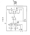
- Fig. 5 shows an example of the coil driving circuit 16.
- a positive potential or variable resistance and a negative potential are set by potentiometers 71 and 72, respectively, and switches 74 and 75 included in an analog switch 73 are closed by the recording mode signal 41 and erasing mode signal 42, respectively.
- the positive potential set by the potentiometer 71 is applied to an operational amplifier 76, and thus a transistor 77 is turned on. Then, a current having a value which is obtained by dividing the positive potential from the potentiometer 71 by the resistance of a resistor 79, flows through the electromagnetic coil 10.
- a stationary magnetic field when information is recorded or erased, a stationary magnetic field can be applied to a magnetic recording film in a direction corresponding to a recording operation or erasing operation, without paying special regard to conventional magnetic field generating means, that is, an electromagnetic coil for generating an external magnetic field and a coil driving circuit, and thus information can be recorded or erased stably and at high speed.
Abstract
Description
- The present invention relates to a magneto-optical information processing method and a magneto-optical information processing apparatus, in both of which information is recorded and erased by utilizing a light induced thermo-magnetic effect and is reproduced on the basis of the magneto-optic effect, and more particularly to the above method and apparatus capable of applying a stable magnetic field to a magnetic recording medium in a recording operation and an erasing operation.
- A magneto-optical information storage apparatus is disclosed in, for example, an article entitled "Amorphous thin film disk for magneto-optical memory" by NHK Broadcasting Science Research Laboratories, SPIE, Vol. 329, page 208, Optical Disc Technology, 1982. An apparatus of this kind is made up of a recording/reproducing optical system and an electromagnetic coil, and the electromagnetic coil is disposed so that a recording medium is sandwiched between the electromagnetic coil and a focusing lens. Further, a magneto-optical information processing apparatus generally uses a perpendicular magnetic thin film as the information recording medium, and a recording operation is performed by reversing the direction of magnetization of the magnetic thin film in accordance with information. Further, a reproducing operation is performed by utilizing a phenomenon that the plane of polarization of light incident on the magnetic thin film is rotated depending upon the direction of magnetization of thereof, that is, the magneto-optic effect. In this apparatus, recorded information is erasable or rewritable. In more detail, a recording operation and an erasing operation are performed in such a manner that a portion of the mgnetic thin film is heated by a laser beam which is focused on the portion, so that the magnetization at the portion is extinguished, and then an external magnetic field in a desired direction is applied to the portion by an electromagnetic coil, to establish fixed magnetization at the portion, that is, the recording and erasing operations are performed on the basis of a light induced thermo-magnetic effect. However, it is required to make the direction of magnetic field applied in the recording operation opposite to the direction of magnetic field applied in the erasing operation. Further, it is important to reverse the direction of applied magnetic field at high speed. Accordingly, in a magneto-optical information processing apparatus, it is very important how stably an external magnetic field is applied to a magentic recording medium to enhance the processing speed and reliability of the apparatus.
- It is an object of the present invention to provide a magneto-optical information processing method and a magneto-optical information processing apparatus, in both of which a stable, stationary magnetic field is applied to a recording medium in recording and erasing operations, to record and erase information stably and at high speed.
- In order to attain the above object, according to the present invention, prior to irradiating that portion of a recording medium which is to be subjected to a recording or erasing operation, with a light pulse, an external magnetic field is applied to the recording medium so that the intensity of the external magnetic field at the portion reaches a stationary value when the portion is irradiated with the light pulse. In general, the risetime of a magnetic field generated by an electromagnetic coil is dependent upon the time constant of the coil. In order to generate a strong magnetic field, it is required not.only to make large the inductance of the coil but also to make large a driving current flowing through the coil. However, it is very difficult to perform a high-speed switching operation for a large driving current by a driver circuit of the coil. Further, when a saturation switching circuit is used, it is impossible to form a stationary magnetic field in a period which is shorter than the time constant of the coil. The high-speed switching may be realized by placing the coil in close proximity to the recording medium and by making the coil small in size. In this case, however, the most important advantage of the magneto-optical information processing apparatus-thai information can be recorded, erased and reproduced by the non-contact method, will be lost.
- According to the present invention, taking into consideration of the risetime of magnetic field, a current is forced to flow through the electromagnetic coil prior to irradiating the recording medium with the light pulse. Thus, the recording and erasing operation are performed after the magnetic field has reached a stationary state.
- For example, let us consider a magneto-optical disk in which a sector is used as a processing unit, a host control unit can readily identify a sector which is to be subjected to a recording or erasing operation. According to the present invention, a reproducing operation for at least one track is performed between a recording operation and an erasing operation which are opposite in direction of applied magnetic field to each other, and a driving current having a desired direction is caused to flow through a coil when a sector that precedes a target sector (in which information is to be recorded or erased) by an amount corresponding to the time constant of the coil, is detected, and thus the direction of applied magnetic field can be changed before the target sector is irradiated with a light pulse.
-
- Fig. 1 is a diagram, partly schematic and partly in block, of an embodiment of a magneto-optical disk apparatus according to the present invention.
- Fig. 2 is a schematic diagram showing an example of the recording format of the disk used in the embodiment of Fig. 1.
- Fig. 3 is a time chart for explaining an example of a sequential operation for recording, erasing and reproducing information, according to the present invention.
- Fig. 4 is a block diagram showing an example of a logic circuit for controlling the generation of magnetic field.
- Fig. 5 is a circuit diagram showing an example of a coil driving circuit for a magnetic field generating coil.
- The present invention will be explained below in detail, with reference to the drawings.
- Fig. 1 is a diagram, partly schematic and partly in block, of an embodiment of a magneto-optical disk apparatus according to the present invention. Referring to Fig. 1, a disk-shaped, magneto-optical recording member (hereinafter referred to as "magneto-optical disk") 1 is rotated by an electric motor 2, and a magneto-
optic head 3 for recording, reproducing and erasing information can be moved by a carriage motor (for example, a linear motor) 3 in a radial direction of thedisk 1 so as to reach a desired track on thedisk 1. The magneto-optical disk 1 has a substrate made of glass, plastics, or others and a perpendicular magnetic film which is formed on the substrate and made of, for example, TbFe so as to have the magneto-optic effect. The magnetic film may be sandwiched between a pair of protective layers which are made of, for example, SiO2. A laser beam emitted from alight source 5 such as a semiconductor laser is converted by a coupling lens 6 into a parallel beam, and then passes through a beam splitter 7 and an objective 8 to form a fine light spot on thedisk 1. In a case where the laser beam emitted from the semiconductor laser has an elliptical cross section, a light beam transform optical system formed of, for example, a triangular prism is interposed between the lens 6 and the beam splitter 7 to transform the above laser beam into a laser beam having a circular cross section. In order that the objective 8 can follow the vertical motion of thedisk 1, the objective 8 is mounted on a voice coil 9. In a case where information is recorded on thedisk 1, the driving current of thesemiconductor laser 5 is modulated by a modulation circuit in accordance with an information signal, and the magnetic film of thedisk 1 is irradiated with a light pulse corresponding to information which is to be recorded. Thus, the magnetic film is locally heated, and the magnetization of the film is locally extinguished. A portion of the magnetic film where the magnetization is extinguished, is applied with a magnetic field whose direction is opposite to the direction of magnetization in the neighborhood of the portion, by anelectromagnetic coil 10 which is disposed so that thedisk 1 is interposed between the objective 8 and thecoil 10. Thus, a region having reversed magnetization (namely, a magnetic domain) is formed at the light irradiated portion of the magnetic film. In a case where recorded information is erased, a constant current is caused to flow through thesemiconductor laser 5, to irradiate the magnetic film with a laser beam having a predetermined intensity, thereby distinguishing the magnetization of the magnetic film. Then, a magnetic field which is opposite in direction to the magnetic field applied in the recording operation, is applied to the magnetic film by theelectromagnetic coil 10, to magnetize a light irradiated portion in the same direction as the direction of magnetization in a surrounding non-recorded area. - The magnetization information recorded in the above-mentioned manner is reproduced by utilizing a magneto-optic effect such as the Kerr effect. The term "Kerr effect" indicates a phenomenon that the plane of polarization of light incident upon a magnetic film is rotated in opposite directions depending upon whether the magnetic film is magnetized upwardly or downwardly. Referring lack to Fig. 1, light reflected back from the
disk 1 passes through the objective 8, and is then separated from the incident light by the beam splitter 7. The reflected light thus separated is led to ananalyzer 12. Theanalyzer 12 allows only a polarized light component to ¿ass therethrough. Accordingly, the rotation of the plane of polarization corresponding to whether a recorded portion is present or not and based upon the Kerr effect is converted by theanalyzer 12 into a change in light quantity. The change in light quantity is converted by a photo-detector 13 into an electric signal, which is amplified by anamplifier 14 to a desired level. Acontrol unit 15 for controlling the whole of the embodiment, can control not only various parts such as thecarriage motor 4, themodulation circuit 10, and thecoil driving circuit 16 of theelectromagnetic coil 10, but also various- operations such as an information recording operation, an information reproducing operation, and an information erasing operation. - Now, exemplary numerical values with respect to the external magnetic field applied to the magnetic film will be described below. When information is recorded or erased, the external magnetic field has an intensity of about 200 Oe (oersted) at the magnetic film. Such a magnetic field can be formed by passing a current of about 50 mA through an electromagnetic coil having an inductance of 300 mH. The time constant of this coil is about 3 ms.
- Next, explanation will be made of the magneto-optical disk used in the present invention. Fig. 2 shows an example of the format of the
disk 1. Referring to Fig. 2, a spiral track or a plurality of concentric tracks are formed on thedisk 1 along the rotational direction thereof. One track corresponding to the circumference of thedisk 1 is divided into a plurality ofrecording regions 21 to 28. Each of these recording regions is called "sector", and is used as a unit for recording, reproducing and erasing information.Header portions 31 to 38 are provided at the tops of thetracks 21 to 28, respectively. Addresses for indentifying a sector such as a.track number and a sector number, a sector mark indicating the starting point of the sector, and items necessary for recording information in and reproducing information from the sector such.as a synchronizing signal, are previously written in the header portion in the form of an uneven pattern due to pit distribution (that is, an uneven pattern having a phase structure). Further, in order that the light spot can scan each track accurately, an optically detectable guide groove serving as an optical guide is previously on thedisk 1 in the form of a spiral or concentric circles, if necessary. The pits at the header portion may be formed in a guide groove, or may be formed in a flat region between adjacent guide grooves. However, in the magneto-optical disk, from which information is reproduced by detecting-only a little rotation of the plane of polarization of incident light due to the magneto-optic effect, it is preferred to previously record header information in the flat region between adjacent guide grooves, and to record magnetization information of the data portion of each sector also in the flat region between adjacent guide grooves, since an S/N ratio is improved. - Pits at the header portion can be detected from the output of the photo-
detector 13. Alternatively, another beam splitter formed of a polarization prism is interposed between the beam splitter 7 and theanalyzer 12, and the pits can be detected on the basis of the quantity of light passing through another beam splitter. Further, by using the light having passed through another beam splitter, signals for controlling the position of the light spot (that is, a focusing signal and a tracking signal) can be detected. For example, the light having passed through another beam splitter is divided by a further beam splitter (formed of, for example, a half prism) into two parts, one of which is led to a circular photodetector composed of a pair of equal parts through a spherical lens, to detect the tracking signal from the difference between two outputs of the photo-detector. While, the other light part passes through an astigmatic optical system which is made up of a spherical lens and a cylindrical lens. Part of the light having passed through the astigmatic optical system is intercepted by a knife edge, and the remaining part is led to a semicircular photo-detector composed of a pair of equal parts, to detect the focusing signal from the difference between two outputs of the photo-detector. In this case, the photo-detector for detecting the tracking signal also can be used for detcting the header signal, that is, the header signal can be detected from the sum of two outputs of this photo-detector. The header signal detecting system, the tracking signal detecting system and the focusing signal detecting system have no immediate connection with the present invention, and therefore these systems are omitted in the drawings for brevity's sake. The details of the above systems are described in, for example, a U.S. patent application entitled "Apparatus and Record Carrier for Magneto-optical Disc Memory and Master Disc Cutting Apparatus" filed Dec. 21, 1984 by Atsushi Saito, Masahiro Ojima and Masaru Itp, which is entitled to the benefit of the filing date of each of a Japanese patent application Appl. No. sho 58-242006 filed Dec. 23, 1983 and a Japanese patent application Appl. No. sho-133156 filed June 29, 1984. - Further, the pit information at the header portion and the magnetization information at the data portion can be detected in the following manner. The combination of a halfwave plate and a polarization beam splitter is used in place of the
analyzer 12, and light passing through the polarization beam splitter and light reflected from the polarization beam splitter are detected by a pair of photo-detectors independently of each other. Then, the magnetization information is detected from the difference between the outputs of the photo-detectors, and the pit information is detected from the sum of the outputs of the photo-detectors. - Next, explanation will be made of an information recording operation, an information reproducing operation and an information erasing operation, each of which is performed for each sector.
- Fig. 3 shows an example of a time chart for a case where one track corresponding to the circumference of the disk is used as the fundamental unit of each of the recording, reproducing and erasing operations, and information is recorded or erased at a given sector of a track. As shown in parts (E) and (F) of Fig. 3, the direction of applied magnetic field is changed at intervals of one or more tracks, and the irradiation of laser light is carried out for each sector. Further, as shown in part (A) of Fig. 3, a reproducing operation for one track is performed between a recording operation and an erasing operation. This reproducing operation is performed not only to ascertain the recording and erasure of information, but also to eliminate the adverse effects of the risetime and falltime of a magnetic field which is generated by the
electromagnetic coil 10, on the recording and erasing operations. That is, the above adverse effect can be eliminated by performing a reproducing operation for one or more tracks between a recording operation and an erasing operation. Referring to part (B) of Fig. 3, a case where a recording mode at several tracks is instructed by thecontrol unit 15, is indicated by arecording mode signal 41. As shown in part (B) of Fig. 3, a recording mode is started at a position that precedes a desired sector which is contained in a desired track and is to be subjected to the recording operation, by a distance corresponding to the risetime of magnetic field generated by theelectromagnetic coil 10, for example, by one sector. In a case where the risetime of the magnetic field is long and hence it is impossible to apply a stationary magnetic field to the desired sector by starting the recording mode at the position which precedes the desired sector by one sector, the recording mode is started at a position which precedes the desired sector by two or more sectors. When the recording mode is started, a coil driving current 43 shown in part (D) of Fig.-3 is generated by thecoil driving circuit 16, and is applied to theelectromagnetic coil 10, to generate a recordingmagnetic field 44 as shown in part (E) of Fig. 3. After the recording magnetic field has reached a stationary state,laser driving pulses 45 shown in part (F) of Fig. 3 are applied to the modulation circuit 11, to modulate thesemiconductor laser 5 so that the magnetic recording film on thedisk 1 is irradiated with relatively strong light pulses enough to extinguish the magnetization of the recording film. Thus, desired magnetization information can be stably recorded. - Magnetization information recorded on the
disk 1 can be erased in a manner similar to the above-mentioned. Referring to part (C) of Fig. 3, it is indicated by an erasingmode signal 42 that an erasing mode at a track is instructed by thecontrol unit 15. When the erasing mode is started, thecoil driving circuit 16 passes the coil driving current 43 through theelectromagnetic coil 10 in a direction opposite to the direction of coil driving current in the recording mode. Like the recording mode, the erasing mode is started at a position that precedes a desired sector which is contained in a desired track and is to be subjected to an erasing operation, by one or more sectors, that is, an erasing magnetic field is generated at the above position. After the erasing magnetic field has reached a stationary state, thelaser driving pulses 45 are applied to the modulation circuit 11, to modulate thesemiconductor laser 5 so that the magnetic recording film is irradiated with strong light pulses having an output level. Thus, recorded information is surely erased. In part (F) of Fig. 3, in order to perform the erasing operation for a plurality of sectors continuously, thelaser driving pusles 45 are replaced by a D.C current having a constant level. - For example, in a case where the
disc 1 includes a single amorphous film made of a Tb-Fe compound, in order to stably perform a recording operation and an erasing operation, the light power at the film and the intensity of applied magnetic field are made equal to 5 mW and 100 Oe, respectively, in the recording operation, and are made equal to 5 mW and 300 Oe in the erasing operation. - When a reproducing operation is performed, the recording film is irradiated with the laser beam having a small, constant intensity insufficient to extinguish the magnetization of the recording film, and the rotational state of the plane of polarization of reflected light is detected, to be used for reproducing magnetization information. That is, in the reproducing mode, the intensity of the laser beam is too weak to extinguish the magnetization of the recording film, and therefore an external magnetic field used in a preceding mode may be applied to the recording film, as it is. In the present embodiment, however, no external magnetic field is applied to the recording film in the reproducing mode for the following reason. When the magneto-optical recording film is made of a material having a large coercive force, information recorded in the recording film is stable, but a light pulse of large power is required to record and erase information. On the other hand, when the recording film is made of a material having a small coercive force, a light pulse for recording and erasing information may be small in power, but information recorded in the recording film is readily affected by an external magnetic field. In the present embodiment, any external magnetic field is not applied to the recording film in the reproducing mode, to reduce light power required for recording and erasing information, without any danger of the recorded information being affected by an external magnetic field.
- Next, explanation will be made of the circuit configuration of a logical circuit for performing the sequential operation shown in Fig. 3 and the construction of the
coil driving circuit 16 for generating a magnetic field. Various well-known circuits can be used as the semiconductor laser modulation circuit 11, without necessitating any special modification or additional parts, and therefore explanation of the modulation circuit 11 will be omitted. Fig. 4 shows an example of a logical circuit included in thecontrol unit 15 for performing the sequential operation of Fig. 3. Referring to Fig. 4, the logical circuit receivesserial data 51 indicative of the number of the present sector, a signal for marking off theserial data 51, that is, alatch signal 52, and amode signal 61 for specifying a mode (namely, one of recording, erasing and reproducing modes) at a target sector. Theserial data 51 indicative of a sector number is previously written in each of theheader portions 31 to 38 in the form of a train of pits. Thelatch signal 52 is a signal for converting theserial data 51 indicative of the sector number into parallel data. A time when the above conversion is performed, is determined by the number of clock pulses applied after a sector mark which indicates the starting position of each sector, was detected. Thedata 51 and signal 52 are obtained from header information which is reproduced by thehead 3. Themode signal 61 is issued by thecontrol unit 15, and specifies one of the recording, reproducing and erasing modes. Accordingly, when themode signal 61 is expressed by a binary signal, two signal lines are required to form themode signal 61. - The
serial data 51 which is read out by thehead 3 and indicates a sector number, is applied to ashift register 53, to be converted by thelatch signal 52 intoparallel data 54, which is added to a predetermined value (that is, anumeral value 1 in the present embodiment) at anadder 55.Data 56 from theadder 55 is compared by acomparator 59 with thenumber 58 of the target sector which is to be put in a desired mode. Thenumber 58 of the target sector is read out of amemory 57. When thedata 56 coincides with thenumber 58 of the target.sector, a signal indicating coincidence (namely, a coincidence signal) 60 is delivered from thecomparator 59. While, themode signal 16 is previously applied to aselector 62, to put a flip-flop 63 in a waiting state, for the recording mode, and to put a flip-flop 64 in a waiting state, for the erasing mode. For the reproducing mode, both of the flip-flops selector 62 controls the operations of the flip-flops flop 63 is put to a high potential level. For the erasing mode, the data terminal of the flip-flop 64 is put to a high potential level. Thecoincidence signal 60 is applied to the trigger terminal (namley, T-terminal) of each flip-flop, and thus only a flip-flop whose D-terminal is put to the high potential level, is set. Further, for the reproducing mode, the flip-flops flop 63 put in the waiting state is set by thecoincidence signal 60, and thus therecording mode signal 41 from the flip-flop 63 takes a high level. The recording mode is reset when themode signal 61 indicating the reproducing mode is issued from thecontrol unit 15. For the erasing mode, the flip-flop 64 put in the waiting state is set by thecoincidence signal 60, and thus the erasingmode signal 42 from the flip-flop 64 takes a high level. - In order to perform recording and erasing operations, it is required to apply a magnetic field to the recording film and to irradiate the recording film with a relatively strong light pulse. The risetime of the light pulse is in the order of one nanosecond, and is negligibly small as compared with the risetime of the magnetic field. Accordingly, the light pulse is given to a sector which is to be subjected to a recording or erasing operation, without paying special regard to time delay, in such a manner that the intensity of the light pulse is varied in accordance with header information of the sector.
- A main feature of the logical circuit shown in Fig. 4 resides in that the number of the sector which is located behind the present sector (now receiving a light spot) by one sector, is compared with the number of the target sector, to detect a time when the light spot is placed on a sector which precedes the target sector by one sector. Although the number of the sector which is located behind the present sector by one sector, is compared with the number of the target sector in the logical circuit of Fig. 4, the number of the sector which preceds the target sector by one sector, may be determined by using a subtracter, to be compared with the number of the present target. Further, the
data 56 may be obtained not by theadder 56"but by a software for operating the.control unit 15. - Next, explanation will be made of the
coil driving circuit 15 for generating the recording magnetic field and erasing magnetic field in response to therecording mode signal 41 and erasingmode signal 42, respectively. - Fig. 5 shows an example of the
coil driving circuit 16. Referring to Fig. 5, a positive potential or variable resistance and a negative potential are set bypotentiometers analog switch 73 are closed by therecording mode signal 41 and erasingmode signal 42, respectively. Now, let us consider a case where theswitch 74 is closed by therecording mode signal 41. The positive potential set by thepotentiometer 71 is applied to anoperational amplifier 76, and thus atransistor 77 is turned on. Then, a current having a value which is obtained by dividing the positive potential from thepotentiometer 71 by the resistance of aresistor 79, flows through theelectromagnetic coil 10. While, in a case where theswitch 75 is closed by the erasingmode signal 42, atransistor 78 is turned on, and thus a current having a value which is obtained by dividing the negative potential from thepotentiometer 72 by the resistance of theresistor 79, flows through theelectromagnetic coil 10 in a direction opposite to the direction of the current which flows through thecoil 10 in the recording mode. - When both of the
recording mode signal 41 and erasingmode signal 42 take a low level, theswitches operational amplifier 76 is grounded through a resistor 80 of high resistance, that is, is applied with zero volt. Thus, no current flows through theelectromagnetic coil 10. This state corresponds to the reproducing mode.Diodes 81 and 82 neutralize the base- emitter voltages of thetrainsistor transistors - As has been explained in the foregoing, according to the present invention, when information is recorded or erased, a stationary magnetic field can be applied to a magnetic recording film in a direction corresponding to a recording operation or erasing operation, without paying special regard to conventional magnetic field generating means, that is, an electromagnetic coil for generating an external magnetic field and a coil driving circuit, and thus information can be recorded or erased stably and at high speed.
Claims (11)
Applications Claiming Priority (2)
| Application Number | Priority Date | Filing Date | Title |
|---|---|---|---|
| JP59120000A JPH0619863B2 (en) | 1984-06-13 | 1984-06-13 | Magneto-optical information storage method and device |
| JP120000/84 | 1984-06-13 |
Publications (3)
| Publication Number | Publication Date |
|---|---|
| EP0164745A2 true EP0164745A2 (en) | 1985-12-18 |
| EP0164745A3 EP0164745A3 (en) | 1988-03-30 |
| EP0164745B1 EP0164745B1 (en) | 1992-05-20 |
Family
ID=14775409
Family Applications (1)
| Application Number | Title | Priority Date | Filing Date |
|---|---|---|---|
| EP85107258A Expired - Lifetime EP0164745B1 (en) | 1984-06-13 | 1985-06-12 | Method of and apparatus for recording/erasing information by utilizing light induced thermo-magnetic effect |
Country Status (5)
| Country | Link |
|---|---|
| US (1) | US4712203A (en) |
| EP (1) | EP0164745B1 (en) |
| JP (1) | JPH0619863B2 (en) |
| KR (1) | KR920005757B1 (en) |
| DE (1) | DE3586072D1 (en) |
Cited By (9)
| Publication number | Priority date | Publication date | Assignee | Title |
|---|---|---|---|---|
| EP0241222A1 (en) * | 1986-04-10 | 1987-10-14 | Canon Kabushiki Kaisha | Opto-magnetic recording apparatus for sequentially driving optical head drive means and biasing magnetic field generation means |
| EP0275323A1 (en) * | 1986-07-31 | 1988-07-27 | Sony Corporation | Ferromagnetic recording apparatus |
| EP0276326A1 (en) * | 1986-07-31 | 1988-08-03 | Sony Corporation | Optical disc recording/reproducing apparatus |
| EP0312143A1 (en) * | 1987-10-14 | 1989-04-19 | Koninklijke Philips Electronics N.V. | Magneto-optical recording apparatus and energizing circuit for use in such a magneto-optical recording apparatus |
| EP0342624A2 (en) * | 1988-05-20 | 1989-11-23 | Hitachi, Ltd. | Magneto-optical data recording system |
| FR2632438A1 (en) * | 1988-06-07 | 1989-12-08 | Philips Nv | MAGNETO-OPTICAL RECORDER WITH MAGNETIC FIELD MODULE |
| EP0346063A2 (en) * | 1988-06-09 | 1989-12-13 | Canon Kabushiki Kaisha | Magneto-optical information recording method and apparatus |
| EP0365891A1 (en) * | 1988-10-22 | 1990-05-02 | Deutsche Thomson-Brandt GmbH | Circuit for magnetic or magneto-optical recording of data on a recording medium |
| EP0461132B1 (en) * | 1989-03-04 | 1993-08-11 | Deutsche Thomson-Brandt GmbH | Circuit arrangement for reversing a magnetic field |
Families Citing this family (37)
| Publication number | Priority date | Publication date | Assignee | Title |
|---|---|---|---|---|
| JPH0664767B2 (en) * | 1984-10-12 | 1994-08-22 | 株式会社東芝 | Optical information recording method and optical information recording device |
| JPS61276103A (en) * | 1985-05-31 | 1986-12-06 | Canon Inc | Recording system for photomagnetic memory |
| US4926408A (en) * | 1985-06-14 | 1990-05-15 | Kabushiki Kaisha Toshiba | Magneto-optic recording/erasing system with simultaneous dual head control and disk error detection |
| US4937799A (en) * | 1985-12-13 | 1990-06-26 | Canon Kabushiki Kaisha | Method and apparatus for setting light quantity most suitable for reproducing information from an optical recording medium |
| US4813032A (en) * | 1986-10-17 | 1989-03-14 | Canon Kabushiki Kaisha | Magneto-optical information reproducing apparatus in which the azimuth angle of the transmission axis of an analyzer is optimized so that the C/N ratio of a reproducing signal is maximum |
| US4916680A (en) * | 1986-12-22 | 1990-04-10 | International Business Machines Corporation | Magnetooptic recording member having selectively-reversed erasure directions in predetermined recording areas of the record member |
| US4937800A (en) * | 1986-12-22 | 1990-06-26 | International Business Machines Corporation | Method of recording using selective-erasure directions for magnetooptic record members |
| JPS63167451A (en) * | 1986-12-27 | 1988-07-11 | Toshiba Corp | Information recording and reproducing device |
| JP2682621B2 (en) * | 1987-03-03 | 1997-11-26 | オリンパス光学工業株式会社 | Bias magnetic field abnormality detector |
| JPS63251923A (en) * | 1987-04-08 | 1988-10-19 | Fuji Photo Film Co Ltd | Magnetic recording medium and magnetic recording and reproducing method using said medium |
| US4814903A (en) * | 1987-06-29 | 1989-03-21 | International Business Machines Corporation | Alternate storage areas in magnetooptical media |
| DE3874276T2 (en) * | 1987-10-12 | 1993-03-25 | Philips Nv | READING CIRCUIT OF A DELAY CIRCUIT. |
| US5233577A (en) * | 1987-10-14 | 1993-08-03 | U.S. Philips Corp. | Magneto-optical recording apparatus and energizing circuit for use in such a magneto-optical recording apparatus |
| NL8703011A (en) * | 1987-12-14 | 1989-07-03 | Philips Nv | METHOD FOR RECORDING INFORMATION ON A THERMO-MAGNETIC TYPE RECORD CARRIER, AND AN APPARATUS FOR CARRYING OUT THE METHOD |
| JP2912373B2 (en) * | 1988-04-20 | 1999-06-28 | シャープ株式会社 | Magneto-optical recording / reproducing device |
| US4962492A (en) * | 1988-04-29 | 1990-10-09 | Laser Magnetic Storage International Company | Magneto-optic data recording system, actuating device therefor and method of providing same |
| US5014254A (en) * | 1988-05-09 | 1991-05-07 | U.S. Philips Corporation | Magneto-optical recording method and magneto-optical recording apparatus |
| US5105408A (en) * | 1988-05-12 | 1992-04-14 | Digital Equipment Corporation | Optical head with flying lens |
| US5067117A (en) * | 1988-10-28 | 1991-11-19 | Fuji Electric Co., Ltd. | Output stabilizing apparatus for an optical head |
| JP2701403B2 (en) * | 1988-12-29 | 1998-01-21 | ソニー株式会社 | Magneto-optical disk device |
| DE69022451T2 (en) * | 1989-03-09 | 1996-03-21 | Canon Kk | Magneto-optical recording device with means for delaying the input signal to prevent bit shifting. |
| JPH02287932A (en) * | 1989-04-28 | 1990-11-28 | Toshiba Corp | Optical head |
| US5121369A (en) * | 1989-05-25 | 1992-06-09 | International Business Machines Corporation | Method and apparatus for direct overwriting information on a magneto-optical recording medium using constant laser beam modulated magnetic field generator |
| JPH0340250A (en) * | 1989-07-06 | 1991-02-21 | Matsushita Electric Ind Co Ltd | Magneto-optical disk and magneto-optical disk device |
| US5278809A (en) * | 1990-01-17 | 1994-01-11 | Olympus Optical Co., Ltd. | Photomagnetic recording apparatus recording with alternating magnetic field and D.C. magnetic field |
| NL9001546A (en) * | 1990-07-06 | 1992-02-03 | Philips Nv | DEVICE FOR REGISTERING AND / OR READING A MAGNETO-OPTICAL INFORMATION CARRIER. |
| JP2813261B2 (en) * | 1992-02-14 | 1998-10-22 | シャープ株式会社 | Magnetic head device for magneto-optical disk and magneto-optical recording / reproducing device |
| JP3098896B2 (en) * | 1992-06-23 | 2000-10-16 | キヤノン株式会社 | Magneto-optical recording device |
| JP2539585B2 (en) * | 1993-10-06 | 1996-10-02 | 株式会社日立製作所 | Magneto-optical information storage method |
| US5689479A (en) * | 1995-09-25 | 1997-11-18 | Sony Corporation | Magneto-optical recording apparatus |
| JPH10199064A (en) * | 1997-01-10 | 1998-07-31 | Sony Corp | Device and method for data recording |
| DE19756458A1 (en) * | 1997-12-18 | 1999-06-24 | Thomson Brandt Gmbh | Magneto-optical recording or playback device |
| US6504805B1 (en) * | 1999-07-22 | 2003-01-07 | Terastor Corporation | Track identification generation for optical disk |
| US20020073270A1 (en) * | 2000-12-07 | 2002-06-13 | Benson William E. | Headerless split sector format for optical disk drives |
| US7050256B1 (en) | 2004-06-29 | 2006-05-23 | The United States Of America As Represented By The Administrator Of The National Aeronautics And Space Administration | Fast erase method and apparatus for digital media |
| JP5717423B2 (en) | 2010-11-30 | 2015-05-13 | 株式会社東芝 | Magnetic recording apparatus, controller, and magnetic recording method |
| US11427507B2 (en) | 2016-12-31 | 2022-08-30 | Certainteed Llc | Mineral roofing granules and methods for making them |
Citations (4)
| Publication number | Priority date | Publication date | Assignee | Title |
|---|---|---|---|---|
| FR1529951A (en) * | 1966-05-20 | 1968-06-21 | Olivetti General Electric Spa | Magneto-optical recording device |
| JPS57117106A (en) * | 1981-01-09 | 1982-07-21 | Olympus Optical Co Ltd | Optical magnetic recording and reproducing method |
| EP0106673A2 (en) * | 1982-10-14 | 1984-04-25 | Matsushita Electric Industrial Co., Ltd. | Optical and reversible recording and reproducing apparatus |
| JPS59140635A (en) * | 1983-01-31 | 1984-08-13 | Canon Inc | Optical information recorder |
Family Cites Families (7)
| Publication number | Priority date | Publication date | Assignee | Title |
|---|---|---|---|---|
| US4094013A (en) * | 1975-05-22 | 1978-06-06 | U.S. Philips Corporation | Optical storage disk system with disk track guide sectors |
| JPS5730132A (en) * | 1980-07-29 | 1982-02-18 | Sharp Corp | Magnetooptical storage device |
| JPS5826336A (en) * | 1981-08-06 | 1983-02-16 | Pioneer Electronic Corp | Recorder and reproducer of magnetooptic recording system |
| JPS5843078A (en) * | 1981-09-08 | 1983-03-12 | Omron Tateisi Electronics Co | Memory card |
| NL8203725A (en) * | 1982-09-27 | 1984-04-16 | Philips Nv | THERMO-MAGNETO-OPTICAL MEMORY DEVICE AND RECORD MEDIUM FOR THAT. |
| US4610009A (en) * | 1983-05-23 | 1986-09-02 | Xerox Corporation | Writing, erasing and readout system for a magneto-optic recording medium |
| JPS6013304A (en) * | 1983-07-04 | 1985-01-23 | Victor Co Of Japan Ltd | Erasing device of optical/thermal/magnetic recording |
-
1984
- 1984-06-13 JP JP59120000A patent/JPH0619863B2/en not_active Expired - Lifetime
-
1985
- 1985-06-11 KR KR1019850004089A patent/KR920005757B1/en not_active IP Right Cessation
- 1985-06-12 US US06/743,974 patent/US4712203A/en not_active Expired - Lifetime
- 1985-06-12 EP EP85107258A patent/EP0164745B1/en not_active Expired - Lifetime
- 1985-06-12 DE DE8585107258T patent/DE3586072D1/en not_active Expired - Lifetime
Patent Citations (5)
| Publication number | Priority date | Publication date | Assignee | Title |
|---|---|---|---|---|
| FR1529951A (en) * | 1966-05-20 | 1968-06-21 | Olivetti General Electric Spa | Magneto-optical recording device |
| JPS57117106A (en) * | 1981-01-09 | 1982-07-21 | Olympus Optical Co Ltd | Optical magnetic recording and reproducing method |
| US4472748A (en) * | 1981-01-09 | 1984-09-18 | Olympus Optical Co. Ltd. | Method of processing information signal with respect to opto-magnetic record medium |
| EP0106673A2 (en) * | 1982-10-14 | 1984-04-25 | Matsushita Electric Industrial Co., Ltd. | Optical and reversible recording and reproducing apparatus |
| JPS59140635A (en) * | 1983-01-31 | 1984-08-13 | Canon Inc | Optical information recorder |
Non-Patent Citations (3)
| Title |
|---|
| IBM TECHNICAL DISCLOSURE BULLETIN, vol. 15, no. 9, February 1973, pages 2747-2748, New York, US; W.T. FROST et al.: "Thermomagnetic recording and erasure" * |
| PATENT ABSTRACTS OF JAPAN, vol. 6, no. 212 (P-151)[1090], 26th October 1982; & JP-A-57 117 106 (OLYMPUS K.K.) 21-07-1982 * |
| PATENT ABSTRACTS OF JAPAN, vol. 8, no. 275 (P-321)[1712], 15th December 1984; & JP-A-59 140 635 (CANON K.K.) 13-08-1984 * |
Cited By (19)
| Publication number | Priority date | Publication date | Assignee | Title |
|---|---|---|---|---|
| EP0241222A1 (en) * | 1986-04-10 | 1987-10-14 | Canon Kabushiki Kaisha | Opto-magnetic recording apparatus for sequentially driving optical head drive means and biasing magnetic field generation means |
| US4972395A (en) * | 1986-04-10 | 1990-11-20 | Canon Kabushiki Kaisha | Opto-magnetic recording apparatus for sequentially driving optical head drive means and biasing magnetic field generation means |
| EP0276326A4 (en) * | 1986-07-31 | 1989-09-11 | Sony Corp | Optical disc recording/reproducing apparatus. |
| EP0275323A4 (en) * | 1986-07-31 | 1990-10-10 | Sony Corporation | Ferromagnetic recording apparatus |
| EP0276326A1 (en) * | 1986-07-31 | 1988-08-03 | Sony Corporation | Optical disc recording/reproducing apparatus |
| US5042022A (en) * | 1986-07-31 | 1991-08-20 | Sony Corporation | Optical disk recording/reproducing apparatus with synchronized data writing |
| EP0275323A1 (en) * | 1986-07-31 | 1988-07-27 | Sony Corporation | Ferromagnetic recording apparatus |
| EP0312143A1 (en) * | 1987-10-14 | 1989-04-19 | Koninklijke Philips Electronics N.V. | Magneto-optical recording apparatus and energizing circuit for use in such a magneto-optical recording apparatus |
| US5170383A (en) * | 1988-05-20 | 1992-12-08 | Hitachi, Ltd. | Magneto-optical data recording system |
| EP0342624A3 (en) * | 1988-05-20 | 1990-11-22 | Hitachi, Ltd. | Magneto-optical data recording system |
| EP0342624A2 (en) * | 1988-05-20 | 1989-11-23 | Hitachi, Ltd. | Magneto-optical data recording system |
| US5726955A (en) * | 1988-05-20 | 1998-03-10 | Hitachi, Ltd. | Magneto optical recording medium apparatus and method utilizing light pulse magnetic modulation recording |
| US5959943A (en) * | 1988-05-20 | 1999-09-28 | Hitachi, Ltd. | Information recording medium with clock information therein |
| EP0345877A1 (en) * | 1988-06-07 | 1989-12-13 | Koninklijke Philips Electronics N.V. | Magneto-optical recorder with a modulated magnetic field |
| FR2632438A1 (en) * | 1988-06-07 | 1989-12-08 | Philips Nv | MAGNETO-OPTICAL RECORDER WITH MAGNETIC FIELD MODULE |
| EP0346063A3 (en) * | 1988-06-09 | 1990-07-18 | Canon Kabushiki Kaisha | Magneto-optical information recording method and apparatus |
| EP0346063A2 (en) * | 1988-06-09 | 1989-12-13 | Canon Kabushiki Kaisha | Magneto-optical information recording method and apparatus |
| EP0365891A1 (en) * | 1988-10-22 | 1990-05-02 | Deutsche Thomson-Brandt GmbH | Circuit for magnetic or magneto-optical recording of data on a recording medium |
| EP0461132B1 (en) * | 1989-03-04 | 1993-08-11 | Deutsche Thomson-Brandt GmbH | Circuit arrangement for reversing a magnetic field |
Also Published As
| Publication number | Publication date |
|---|---|
| EP0164745B1 (en) | 1992-05-20 |
| JPH0619863B2 (en) | 1994-03-16 |
| KR920005757B1 (en) | 1992-07-18 |
| US4712203A (en) | 1987-12-08 |
| JPS61950A (en) | 1986-01-06 |
| KR860000636A (en) | 1986-01-30 |
| DE3586072D1 (en) | 1992-06-25 |
| EP0164745A3 (en) | 1988-03-30 |
Similar Documents
| Publication | Publication Date | Title |
|---|---|---|
| US4712203A (en) | Method and apparatus for thermo magnetic recording/erasing information with preselected magnetic field switching | |
| US4539662A (en) | Method and system for optically recording and playing back information on a recording medium having magnetization film thereon | |
| US5199022A (en) | Disk having data memorizing portion including land-shaped and groove-shaped areas, and writing/reading apparatus for the same | |
| US4472748A (en) | Method of processing information signal with respect to opto-magnetic record medium | |
| JP2655682B2 (en) | Magneto-optical information recording / reproducing device | |
| JPH07105081B2 (en) | Magneto-optical disk device and information processing method thereof | |
| US4495530A (en) | Method of processing information signal with respect to opto-magnetic record medium | |
| US5321672A (en) | Method of an apparatus for magneto-optically recording information by changing the position or shape or controlling the diameter of reversed domains | |
| JPS59215008A (en) | Optical magnetic disc device | |
| US5283775A (en) | Split detector system for direct read-while-write operation on magneto-optic media | |
| US4789972A (en) | Selectively controlling the erasure in a magneto-optic recording medium | |
| US5357493A (en) | Magneto-optic memory device for overwriting information on magneto-optic recording medium by using a pair of light spots without using an external magnetic field | |
| US4972395A (en) | Opto-magnetic recording apparatus for sequentially driving optical head drive means and biasing magnetic field generation means | |
| US6212136B1 (en) | Magneto-optical disc apparatus with means to change the angle and distance between a magnetic field generating source and a magneto-optical disc | |
| EP0328667B1 (en) | Magneto-optical storage | |
| CA2026740C (en) | Sensing previously-recorded information while recording or erasing a magnetooptic storage number | |
| JP2604700B2 (en) | Magneto-optical recording / reproduction / erasing method and apparatus | |
| JP3694338B2 (en) | Magneto-optical disk unit | |
| JP2539585B2 (en) | Magneto-optical information storage method | |
| JPS61196446A (en) | Photomagnetic recording device | |
| JP2793294B2 (en) | Information recording / reproducing device | |
| JPS6150235A (en) | System and apparatus for erasing and reproducing optomagnetic recording | |
| JP2872801B2 (en) | Magneto-optical recording / reproducing device | |
| JP2749877B2 (en) | Information recording device | |
| JP2604702B2 (en) | Magneto-optical recording / reproduction / erasing method and apparatus |
Legal Events
| Date | Code | Title | Description |
|---|---|---|---|
| PUAI | Public reference made under article 153(3) epc to a published international application that has entered the european phase |
Free format text: ORIGINAL CODE: 0009012 |
|
| AK | Designated contracting states |
Designated state(s): DE FR GB NL |
|
| PUAL | Search report despatched |
Free format text: ORIGINAL CODE: 0009013 |
|
| AK | Designated contracting states |
Kind code of ref document: A3 Designated state(s): DE FR GB NL |
|
| 17P | Request for examination filed |
Effective date: 19880405 |
|
| 17Q | First examination report despatched |
Effective date: 19890816 |
|
| RBV | Designated contracting states (corrected) |
Designated state(s): DE FR NL |
|
| GRAA | (expected) grant |
Free format text: ORIGINAL CODE: 0009210 |
|
| AK | Designated contracting states |
Kind code of ref document: B1 Designated state(s): DE FR NL |
|
| REF | Corresponds to: |
Ref document number: 3586072 Country of ref document: DE Date of ref document: 19920625 |
|
| ET | Fr: translation filed | ||
| PLBE | No opposition filed within time limit |
Free format text: ORIGINAL CODE: 0009261 |
|
| STAA | Information on the status of an ep patent application or granted ep patent |
Free format text: STATUS: NO OPPOSITION FILED WITHIN TIME LIMIT |
|
| 26N | No opposition filed | ||
| PGFP | Annual fee paid to national office [announced via postgrant information from national office to epo] |
Ref country code: NL Payment date: 20040524 Year of fee payment: 20 |
|
| PGFP | Annual fee paid to national office [announced via postgrant information from national office to epo] |
Ref country code: FR Payment date: 20040526 Year of fee payment: 20 |
|
| PGFP | Annual fee paid to national office [announced via postgrant information from national office to epo] |
Ref country code: DE Payment date: 20040608 Year of fee payment: 20 |
|
| PG25 | Lapsed in a contracting state [announced via postgrant information from national office to epo] |
Ref country code: NL Free format text: LAPSE BECAUSE OF EXPIRATION OF PROTECTION Effective date: 20050612 |
|
| NLV7 | Nl: ceased due to reaching the maximum lifetime of a patent |
Effective date: 20050612 |