EP0106593A2 - Mundstückreguliervorrichtung - Google Patents
Mundstückreguliervorrichtung Download PDFInfo
- Publication number
- EP0106593A2 EP0106593A2 EP83305840A EP83305840A EP0106593A2 EP 0106593 A2 EP0106593 A2 EP 0106593A2 EP 83305840 A EP83305840 A EP 83305840A EP 83305840 A EP83305840 A EP 83305840A EP 0106593 A2 EP0106593 A2 EP 0106593A2
- Authority
- EP
- European Patent Office
- Prior art keywords
- control
- paper
- servo motor
- nozzle
- slice
- Prior art date
- Legal status (The legal status is an assumption and is not a legal conclusion. Google has not performed a legal analysis and makes no representation as to the accuracy of the status listed.)
- Withdrawn
Links
Images

Classifications
-
- D—TEXTILES; PAPER
- D21—PAPER-MAKING; PRODUCTION OF CELLULOSE
- D21F—PAPER-MAKING MACHINES; METHODS OF PRODUCING PAPER THEREON
- D21F1/00—Wet end of machines for making continuous webs of paper
- D21F1/02—Head boxes of Fourdrinier machines
-
- B—PERFORMING OPERATIONS; TRANSPORTING
- B29—WORKING OF PLASTICS; WORKING OF SUBSTANCES IN A PLASTIC STATE IN GENERAL
- B29C—SHAPING OR JOINING OF PLASTICS; SHAPING OF MATERIAL IN A PLASTIC STATE, NOT OTHERWISE PROVIDED FOR; AFTER-TREATMENT OF THE SHAPED PRODUCTS, e.g. REPAIRING
- B29C48/00—Extrusion moulding, i.e. expressing the moulding material through a die or nozzle which imparts the desired form; Apparatus therefor
- B29C48/03—Extrusion moulding, i.e. expressing the moulding material through a die or nozzle which imparts the desired form; Apparatus therefor characterised by the shape of the extruded material at extrusion
- B29C48/07—Flat, e.g. panels
- B29C48/08—Flat, e.g. panels flexible, e.g. films
-
- B—PERFORMING OPERATIONS; TRANSPORTING
- B29—WORKING OF PLASTICS; WORKING OF SUBSTANCES IN A PLASTIC STATE IN GENERAL
- B29C—SHAPING OR JOINING OF PLASTICS; SHAPING OF MATERIAL IN A PLASTIC STATE, NOT OTHERWISE PROVIDED FOR; AFTER-TREATMENT OF THE SHAPED PRODUCTS, e.g. REPAIRING
- B29C48/00—Extrusion moulding, i.e. expressing the moulding material through a die or nozzle which imparts the desired form; Apparatus therefor
- B29C48/25—Component parts, details or accessories; Auxiliary operations
- B29C48/30—Extrusion nozzles or dies
- B29C48/305—Extrusion nozzles or dies having a wide opening, e.g. for forming sheets
- B29C48/31—Extrusion nozzles or dies having a wide opening, e.g. for forming sheets being adjustable, i.e. having adjustable exit sections
- B29C48/313—Extrusion nozzles or dies having a wide opening, e.g. for forming sheets being adjustable, i.e. having adjustable exit sections by positioning the die lips
-
- B—PERFORMING OPERATIONS; TRANSPORTING
- B29—WORKING OF PLASTICS; WORKING OF SUBSTANCES IN A PLASTIC STATE IN GENERAL
- B29C—SHAPING OR JOINING OF PLASTICS; SHAPING OF MATERIAL IN A PLASTIC STATE, NOT OTHERWISE PROVIDED FOR; AFTER-TREATMENT OF THE SHAPED PRODUCTS, e.g. REPAIRING
- B29C48/00—Extrusion moulding, i.e. expressing the moulding material through a die or nozzle which imparts the desired form; Apparatus therefor
- B29C48/25—Component parts, details or accessories; Auxiliary operations
- B29C48/92—Measuring, controlling or regulating
-
- D—TEXTILES; PAPER
- D21—PAPER-MAKING; PRODUCTION OF CELLULOSE
- D21F—PAPER-MAKING MACHINES; METHODS OF PRODUCING PAPER THEREON
- D21F1/00—Wet end of machines for making continuous webs of paper
- D21F1/02—Head boxes of Fourdrinier machines
- D21F1/028—Details of the nozzle section
-
- B—PERFORMING OPERATIONS; TRANSPORTING
- B29—WORKING OF PLASTICS; WORKING OF SUBSTANCES IN A PLASTIC STATE IN GENERAL
- B29C—SHAPING OR JOINING OF PLASTICS; SHAPING OF MATERIAL IN A PLASTIC STATE, NOT OTHERWISE PROVIDED FOR; AFTER-TREATMENT OF THE SHAPED PRODUCTS, e.g. REPAIRING
- B29C2948/00—Indexing scheme relating to extrusion moulding
- B29C2948/92—Measuring, controlling or regulating
- B29C2948/92009—Measured parameter
- B29C2948/92076—Position, e.g. linear or angular
-
- B—PERFORMING OPERATIONS; TRANSPORTING
- B29—WORKING OF PLASTICS; WORKING OF SUBSTANCES IN A PLASTIC STATE IN GENERAL
- B29C—SHAPING OR JOINING OF PLASTICS; SHAPING OF MATERIAL IN A PLASTIC STATE, NOT OTHERWISE PROVIDED FOR; AFTER-TREATMENT OF THE SHAPED PRODUCTS, e.g. REPAIRING
- B29C2948/00—Indexing scheme relating to extrusion moulding
- B29C2948/92—Measuring, controlling or regulating
- B29C2948/92009—Measured parameter
- B29C2948/92114—Dimensions
-
- B—PERFORMING OPERATIONS; TRANSPORTING
- B29—WORKING OF PLASTICS; WORKING OF SUBSTANCES IN A PLASTIC STATE IN GENERAL
- B29C—SHAPING OR JOINING OF PLASTICS; SHAPING OF MATERIAL IN A PLASTIC STATE, NOT OTHERWISE PROVIDED FOR; AFTER-TREATMENT OF THE SHAPED PRODUCTS, e.g. REPAIRING
- B29C2948/00—Indexing scheme relating to extrusion moulding
- B29C2948/92—Measuring, controlling or regulating
- B29C2948/92323—Location or phase of measurement
- B29C2948/92361—Extrusion unit
- B29C2948/92409—Die; Nozzle zone
-
- B—PERFORMING OPERATIONS; TRANSPORTING
- B29—WORKING OF PLASTICS; WORKING OF SUBSTANCES IN A PLASTIC STATE IN GENERAL
- B29C—SHAPING OR JOINING OF PLASTICS; SHAPING OF MATERIAL IN A PLASTIC STATE, NOT OTHERWISE PROVIDED FOR; AFTER-TREATMENT OF THE SHAPED PRODUCTS, e.g. REPAIRING
- B29C2948/00—Indexing scheme relating to extrusion moulding
- B29C2948/92—Measuring, controlling or regulating
- B29C2948/92504—Controlled parameter
- B29C2948/92571—Position, e.g. linear or angular
-
- B—PERFORMING OPERATIONS; TRANSPORTING
- B29—WORKING OF PLASTICS; WORKING OF SUBSTANCES IN A PLASTIC STATE IN GENERAL
- B29C—SHAPING OR JOINING OF PLASTICS; SHAPING OF MATERIAL IN A PLASTIC STATE, NOT OTHERWISE PROVIDED FOR; AFTER-TREATMENT OF THE SHAPED PRODUCTS, e.g. REPAIRING
- B29C2948/00—Indexing scheme relating to extrusion moulding
- B29C2948/92—Measuring, controlling or regulating
- B29C2948/92819—Location or phase of control
- B29C2948/92857—Extrusion unit
- B29C2948/92904—Die; Nozzle zone
Definitions
- This invention relates to apparatus for controlling the delivery of a flowable material through an elongate nozzle whose long edges are relatively displaceable to adjust the delivery height of the nozzle.
- nozzles On paper machines, such nozzles are normally used to deliver the stock constituting the flowable material in a horizontal plane so that it is appropriate to refer to the delivery height of the nozzle. In plastics film extrusion the film may be delivered vertically.
- delivery height will be used generally to mean the separation between - the long edges of the nozzle. More particularly the invention is concerned with such apparatus in which the delivery height of the nozzle is to be differentially adjusted along its length so as to obtain a desired nozzle profile.
- the nozzle in that case is defined by what is called a slice comprising upper and lower parts, which in certain types of slice may be referred to with usually the lower part fixed and referred to as lips, with usually the lower part fixed and the upper part adjustable relative thereto at a number of points across the width of the nozzle.
- the term "across the width” is generally used herein to refer to the elongate direction of the nozzle transverse to the direction of material flow.
- the invention will be particularly discussed with reference to slice control in a paper-making machine. Still more particularly, the discussion will be given with reference to a projection slice having an upper and a lower lip shaped to provide a transverse horizontal nozzle for projecting the stock on to the wire on which the web is formed.
- the invention is applicable with other types of slice such as the vertically-acting gate slice.
- the lower slice lip is fixed extending away from the headbox while the upper slice lip is pivotally mounted at the headbox such that the position of the lip is adjustable to control the height, (i.e. the vertical extent) of the slice opening.
- a monitor gauge or gauges may be located downstream to measure the paper grammage across the web from which adjustment information is obtained.
- Modern paper-making requires increasingly close control of the web characteristics and it is desirable to provide a means of adjusting the height of the slice opening that is readily integrated into a modern automatic control system.
- the adjustment arrangement should be as compact as possible, while providing accurate control at relatively low cost.
- the lip or bar In the general control of the positioning of the slice lip in a projection lip or of the profile bar in a gate-slice, it is important the lip or bar should not be distorted to such a degree that it exceeds the elastic limit since this would result in a permanent set thereby damaging the slice. 'Where the profile control is exercised as part of an overall control system, the system may include special control facilities to prevent such an occurrence. Otherwise some form of fail safe spring linkage can be used in the adjustment devices. The control option is cumbersome and not, in practice, totally safe: the spring linkage usually results in some undue backlash.
- the adjustment device embodying the invention described hereinafter employs an electro-hydraulic actuator which enables accurate control of the upper force limit to be. obtained. It also includes means for measuring the local width (delivery height) of the slice and it is integratable into an automatic control system.
- the present invention can be applied in connection with a plastics extrusion die.
- Such dies are known, for example, from United States Patents 3,940,221 (Nissel) and 2,938,231 (Lowey): both describe extrusion dies for sheet formation with control means by which the nozzle delivery height between the die lips is adjustable, such adjustment being applied at points along the nozzle length to obtain a desired nozzle profile. 2 he control means uses thermally controlled rods whose expansion and contraction with temperature is used to adjust the position of one of the die lips or blades with respect to the other. The reader is directed to those patents for a fuller description of the dies and the manner in which they are adjusted.
- the Nissel patent discloses the use of a downstream gauge to monitor the thickness of plastic sheet or film across its width. The measurements are used to generate error signals for each thermally controlled rod in dependence on whether the measured thickness at the portion of the film or sheet aligned with the rod is greater or less than the desired thickness.
- the control exercised appears to be to simply heat or let cool the relevant rod without any measure of the delivery height at the nozzle itself and without attention being given to the effect of the setting of adjacent rods.
- any thermal control involves a time delay and fast precise adjustment is not possible.
- the invention is concerned with apparatus comprising first and second relatively displaceable parts defining an elongate nozzle through which a flowable material is deliverable, the parts being relatively displaceable to control the delivery height of the nozzle and control means for adjusting the delivery height comprising a plurality of adjustment devices mounted at locations along the length of the nozzle and each connected to one of said parts to locally adjust the delivery height.
- each adjustment device comprises an actuator including an hydraulic servo motor having an output member connected to the said one j part and means for controlling the servo motor in response to an input signal representing a desired local position of the said one part to which the device is connected, a displacement measuring device connected to said output member to provide a signal representing the position of said output member, and said control means including means for comparing the input signal with the position signal to control the servomotor in dependence upon the comparison.
- each adjustment device is connected to the first part and the second part is made fixed.
- a more particular application of the invention is to a paper-making machine in which feed stock is delivered from a headbox on to a wire through a slice for controlling the delivery of the stock, the slice comprising a movable part extending across the wire to control the delivery height of the slice, and the machine including a plurality of adjustment devices mounted at locations across the wire and connected to the movable part to locally adjust the delivery height.
- each adjustment device comprises an actuator including an hydraulic servo motor having an output member connected to said part and means for controlling the servo motor in response to an input signal representing a desired local position of said part, a displacement measuring device connected to said output member to provide a signal representing the position of said output member, and said control means including means for comparing the input signal with the position signal to control the servomotor in dependence upon the comparison.
- control means comprises a servocontrol valve to control the flow of pressure fluid to said servomotor and an electrically energized motor to control the position of said servocontrol valve, said electrically energized motor being energized by a signal dependent on the comparison of the input signal and the position-representing signal.
- said displacement measuring device comprises two relatively movable portions whose relative displacement is sensed, one portion being coupled to the output member of the servo motor and-the other portion supported fixedly with respect to the second fixed part, which in the case of the above paper-making machine is the second fixed part of the slice.
- the support in this case in the paper-making machine may be a rigid beam that is considered to be fixed with respect to the fixed part of the slice.
- the other portion of the displacement measuring device is supported fixedly with respect to the bed of the apparatus or machine which may be expected to provide an even more rigid datum than a fixed beam.
- the displacement measuring device is preferably a linear voltage differential transformer.
- a paper-making machine in accord with the invention and having the preferred control means Day be adapted to have the nozzle profile automatically controlled.
- the machine may further comprise a computer connected to each adjustment device to supply the relevant input signal thereto and a gauge device mounted downstream of the wire to measure the grammage profile of the paper web across the width of the web.
- the gauge device is coupled to the computer to supply profile measurement signals thereto.
- the computer has entered into it and stores a desired grammage profile for the web and is programmed to compute a profile for the delivery height of the nozzle that will produce the desired grammage profile.
- the computer supplies the input signals to the adjustment devices in accord with the computed profile for the nozzle delivery height.
- Such an automatic control system takes advantage of the relatively rapid and precise response of the electro-hydraulic adjustment devices, aided by the measurement of the local delivery height at each device.
- the - computation of the delivery height profile is in practice more complex than a simple adjustment of each adjustment device in dependence on whether the gauge measurement on the portion of the paper web longitudinally aligned with the adjustment device in question is above or below a set value.
- the adjustment of one device also affects delivery at neighbouring devices and account is taken of this.
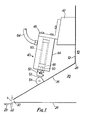
- the headbox 10 of a paper-making machine has a forward end wall 12 from which leads a projection slice 20 through which stock is delivered to the Foudrinier wire 22 moving in the direction of the arrow 23.
- the projection slice comprises a fixed lower slice lip 24 and an upper slice lip 26 pivotally mounted at 28 to the headbox and converging toward the lower lip in the delivery direction to form a horizontal output - nozzle 30 which extends transversely across the wire - perpendicular to the direction of wire motion - and whose height S (in the vertical direction) is to be controlled so as to control the delivery of stock to the wire.
- To pivot the upper lip 26 to control the nozzle height a series of adjustment devices 40, just one of which is shown, are mounted across the upper slice lip to control the nozzle height at the respective locations across the projection slice and thereby control the grammage of the web being formed.
- the apparatus as described thus far in general terms is conventional and the machine itself need not be discussed further. Attention will be concentrated on the particular design and arrangement of the adjustment devices 40.
- the adjustment devices are all of like construction and a description need be given of just a single device.
- a beam 42 Mounted transversely on the front wall 12 of the headbox 10 is a beam 42 to which the housing 44 of each device 40 is secured by a respective bracket 46.
- an actuator including a servo motor having a double-acting piston 48 with a piston rod 50 projecting out of the housing to provide the actuating member.
- the rod 50 is coupled by a clamp 52 to an extension rod 53 that is pivotally mounted to a pivot assembly 54 secured part way along the lip 26 in the direction of wire motion.
- the actuator also contains a servo control-valve for the servo motor and an electrically-operated torque motor for driving the control valve as will be discussed hereinafter with reference to Fig. 3•
- the housing also contains a precision displacement measuring device 60 that is aligned with the piston rod 50.
- the .. device 60 is constituted by a linear voltage differential transformer (LVDT).
- the transformer 60 has an axially movable core (not shown) from which an integral member 62 axially extends.
- the member 62 (Fig. 3) is parallel with rod 50 and connected in the clamp 52 to move with the rod.
- LVDTs are well known displacement-measuring devices and need no further description here. From the device 60 there is obtained an electrical output voltage that is a linear function of displacement.
- the housing also contains an inlet and an outlet for pressure fluid, one 64 of which is seen in Fig. 1.
- the preferred actuator is normally intended for operation with oil as the working fluid. In the present case it is preferred to work with a water-based fluid so that any leakage will not harm the web being formed.
- the datum against which displacement is measured is effectively the wall 12 of the headbox.
- This wall is subject to forces engendered by the actuators of the series of devices 40 and small pressure fluctuations within the headbox. Consequently the wall may flex to a small extent but sufficient to render the displacement measurements of nozzle delivery height as referred to the fixed lower slice lip less accurate than desired.
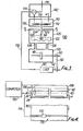
- FIG. 2 of the accompanying drawings there is shown a modification of the device of Fig. 1 in which the displacement measuring device is mounted independently of the actuator.
- the adjustment device 40 is constituted by the electro-hydraulic actuator having the same construction and arrangement as already described.
- the LVDT 60 associated with each device 40 has its body secured to a beam 68.
- the beam is mounted above and perpendicular to the direction of movement of the wire and is supported at each end by any suitable support 66 secured to the base of the machine.
- the beam thus provides a displacement-measurement datum that is fixed relative to the lower slice lip from which the nozzle delivery height is to be measured.
- the core extension member 62 of the LVDT is secured to the pivot assembly 54 so that the extension member 62 moves with displacements of the servo motor piston rod 50.
- the core extension displacement is not now equal to that of the actuator but is directly proportional thereto by a factor derived from the geometry of the assembly.
- ⁇ X and ⁇ Y are displacements of the LVDT 60 and piston rod 50 respectively, and Bis the angle between their lines of action; a is the angle made by the line of action of the LVDT to the lower slice lip, and L 1 and L 2 are the distances from the pivot point 28 of the upper slice lip to the pivot assembly 54 and from this assembly to the end of the lip respectively.
- each device be based on the Series 78 servo valves made by Moog Controls Ltd., of Ashchurch Tewkesbury, Gloucestershire, England, a subsidiary of Moog Servocontrols, Inc. of East Aurora, New York, U.S.A.
- the main parts of such a device are diagranmatically illustrated in Fig. 3.
- Literature containing detailed information is available from Moog Servooontrols, Inc., and for a fuller description of this type of servo valve attention is also directed to U.S. patents 3,023,782 and 3,228,423.
- the torque motor comprises a balanced armature 112 located in the field of a permanent magnet assembly (not shown) to deflect about pivot point 114 in dependence upon the magnetic field induced in the armature by current applied to energizing coils 116.
- the deflection is applied to the servo control valve 120 through an output armature flapper 118 that transmits the armature deflection to the servo control valve 120.
- the valve includes a spool 122 that rests in a central, neutral control position.
- the spool is movable to right or left in dependence on the direction of armature deflection.
- the flapper controls the relative entry of pressure fluid (P S ) through a pair of opposed nozzles - indicated by arrows 124 - that, when the armature is deflected, develops a force on the spool (through means not shown) to move it in a corresponding direction.
- the spool 122 is coupled to the flapper through a cantilever spring 126 that produces a mechanical feedback torque which causes the spool to adopt a position at which the feedback torque balances that of motor 110 and which is a linear function of the input current to coils 116. The armature is restored to its neutral position at this balance position.
- the spool 122 controls ports 128 leading to opposite sides of the piston 48 of the servo motor section 130, the spool opening one or other port to an extent proportional to the magnitude and polarity of the coil current in the torque motor.
- the piston is thus displaced to develop output power, the servo control valve section 120 acting as an hydraulic amplifier between the torque motor and servo motor.
- the servo piston velocity is a function of the torque motor current at a given fluid pressure P 8 .
- the requirement is that the flow of fluid to the motor be terminated when its desired adjustment position is reached. This is achieved by electrical feedback using the LVDT 60 whose core extension 62 is connected by clamp 52 to the output rod 50 of the servo piston 46.
- the highly accurate position-indicative signal obtained from the LVDT 60 (whose other electrical connections are not shown) is applied to a comparison unit 140 over line 132 in which it is compared by a summing circuit 134 with an input control signal applied over the input line 136 representative of the desired height of the slice opening.
- the output signal from the summing circuit causes the armature 112 to deflect until signals over lines 132 and 136 are identical.
- a computer as mentioned below can include any weighting factors, including the geometry of Fig. 2, in calculating the value of the input control signal.
- the rest condition of the servo motor at a given displacement requires a zero output from the summing circuit to the torque motor.
- the adjustment device of Fig.-3 operates with nominally zero position error and the simple direct coupling of the elements to the upper slice lip shown in Figs. 1 and 2 is preferred to minimise the possibility of mechanical backlash.
- the system also does not require a particularly high stability of pressure of the pressure fluid P S . This only influences the response velocity of the servo control, not the final position.
- the Series 78 servo valves available for the above task from Moog Servocontrols have the servo motor 130, servo control valve 120 and torque motor 110 constructed in a single compact housing, the torque motor being isolated from the hydraulic fluid.
- the LVDT 60 is also available located within the housing (in the Fig. 1 assembly) to provide a compact and reliable unit at relatively low cost. It is to be noted that the devices also contain a mechanically settable null adjustment (zero offset) which assists in initial setting up.
- the servo valves described with reference to Fig. 3 are primarily designed for use with oil as the pressure fluid. It is desirable in paper making to use a servo fluid that will avoid as far as possible the risk of spoiling the paper product should any leakage occur.
- One possibility that comes to mind is to use clean water. More preferable, and satisfactory for use with the above-mentioned Series 78 valves of Moog Servocontrols, Inc., is the use of water and ethylene glycol or similar aqueous mixtures as the servo fluid.
- the water-based fluid minimises any possibility of damaging the paper product in the event of leakage and the glycol or other additive acts as a corrosion inhibitor within the servo . mechanism.
- FIG. 4 The use of devices as described with reference to Fig. 3 is also advantageous in connection with automatic control systems. Such a system is shown in broad outline in Fig. 4.
- the devices 40 may be individually controlled manually or by a computer 150 that is responsive to measurements made transverse of the web 160 by a gauge device 170 located at some downstream location in the paper-making machine, and that issues input signals to the respective input lines 136 of the devices 40 over a multi-line bus 152.
- the gauge 170 may, for example, comprise a gauge head 172 that is regularly reciprocated across the web to provide a signal on line 174 that is a profile of the weight of the web across its width (more strictly at an angle to the web path allowing for the motion of the web).
- the computer system is programmed to analyse the profile across the web, to compute the nozzle profile required to obtain a desired grammage profile and to apply signals on lines 136 to adjust the devices 40 to obtain the desired profile. The latter is entered and stored in the computer. This adjustment is in fact complex. For example, a closing of the nozzle height by one device to reduce web thickness will tend to pile up stock to either side requiring adjustment of neighbouring devices.
- the computer uses the gauge measurements to determine a profile for the nozzle height across the wire that will provide the desired weight profile.
- the computer signals the individual devices in accord with its calculated profile.
- the electro-hydraulic servo control now proposed is well suited for incorporation in a-comprehensive control of this kind.
- the apparatus described above has dealt with the control of a projection slice. It will be appreciated that the devices 40 can be connected to adjust a vertically-acting gate slice.
- the servo valves described are capable of developing the high actuating forces required, being operable at pressures of about 1000 psi (6.85 MPa). It will be appreciated, however, that the hydraulic actuator has the advantage that the upper limit of force it can apply is equal to the supply pressure multiplied by the piston area, that is the area of the piston 48 in the servo motor of Fig. 3.
- the device may be rendered fail safe without introducing backlash in the system.
- nozzle control taught by the present specification can be applied to controlling the delivery of other flowable materials through an adjustable elongate nozzle.
Landscapes
- Engineering & Computer Science (AREA)
- Mechanical Engineering (AREA)
- Manufacturing & Machinery (AREA)
- Paper (AREA)
Applications Claiming Priority (4)
| Application Number | Priority Date | Filing Date | Title |
|---|---|---|---|
| GB8228998 | 1982-10-11 | ||
| GB8228998 | 1982-10-11 | ||
| GB8303614 | 1983-02-09 | ||
| GB838303614A GB8303614D0 (en) | 1983-02-09 | 1983-02-09 | Controlled elongate nozzle |
Publications (2)
| Publication Number | Publication Date |
|---|---|
| EP0106593A2 true EP0106593A2 (de) | 1984-04-25 |
| EP0106593A3 EP0106593A3 (de) | 1984-11-28 |
Family
ID=26284089
Family Applications (1)
| Application Number | Title | Priority Date | Filing Date |
|---|---|---|---|
| EP83305840A Withdrawn EP0106593A3 (de) | 1982-10-11 | 1983-09-28 | Mundstückreguliervorrichtung |
Country Status (2)
| Country | Link |
|---|---|
| EP (1) | EP0106593A3 (de) |
| FI (1) | FI833645A7 (de) |
Cited By (5)
| Publication number | Priority date | Publication date | Assignee | Title |
|---|---|---|---|---|
| US5381341A (en) * | 1989-06-01 | 1995-01-10 | Valmet Paper Machinery Incorporated | Control system for a paper or board machine |
| US5827399A (en) * | 1989-07-17 | 1998-10-27 | Valmet Paper Machinery Inc. | Method and system for regulation and on-line measurement of the fibre orientation in a web produced by a paper machine |
| EP0889162A3 (de) * | 1997-07-01 | 1999-06-16 | Voith Sulzer Papiermaschinen GmbH | Former |
| WO2017168053A1 (en) * | 2016-03-31 | 2017-10-05 | Tasowheel Systems Oy | Method and apparatus for adjusting a position of an object and a measuring and adjusting device |
| CN107530911A (zh) * | 2015-03-04 | 2018-01-02 | 艾伯特复合材料公司 | 3d热塑性复合材料的拉挤系统及方法 |
Family Cites Families (4)
| Publication number | Priority date | Publication date | Assignee | Title |
|---|---|---|---|---|
| GB1145299A (en) * | 1966-01-04 | 1969-03-12 | Valmet Oy | Improvements in methods of and arrangements for regulating or eliminating downward deflections of the aprons of headbox slices in paper-machines |
| US3703436A (en) * | 1970-02-03 | 1972-11-21 | Industrial Nucleonics Corp | Anticipatory control of headbox slice opening in a paper machine |
| US3853695A (en) * | 1972-10-12 | 1974-12-10 | S Back | Entraining a liquid into a fiber slurry to accelerate it prior to discharge from a flow path onto a forming wire |
| SE7707981L (sv) * | 1976-12-02 | 1978-06-03 | Ahlstroem Dev Gmbh | Anordning for paverkan av ett banformigt material |
-
1983
- 1983-09-28 EP EP83305840A patent/EP0106593A3/de not_active Withdrawn
- 1983-10-07 FI FI833645A patent/FI833645A7/fi not_active Application Discontinuation
Cited By (6)
| Publication number | Priority date | Publication date | Assignee | Title |
|---|---|---|---|---|
| US5381341A (en) * | 1989-06-01 | 1995-01-10 | Valmet Paper Machinery Incorporated | Control system for a paper or board machine |
| US5827399A (en) * | 1989-07-17 | 1998-10-27 | Valmet Paper Machinery Inc. | Method and system for regulation and on-line measurement of the fibre orientation in a web produced by a paper machine |
| EP0889162A3 (de) * | 1997-07-01 | 1999-06-16 | Voith Sulzer Papiermaschinen GmbH | Former |
| US6139690A (en) * | 1997-07-01 | 2000-10-31 | Voith Sulzer Papiermaschinen Gmbh | Former with a floating upper lip |
| CN107530911A (zh) * | 2015-03-04 | 2018-01-02 | 艾伯特复合材料公司 | 3d热塑性复合材料的拉挤系统及方法 |
| WO2017168053A1 (en) * | 2016-03-31 | 2017-10-05 | Tasowheel Systems Oy | Method and apparatus for adjusting a position of an object and a measuring and adjusting device |
Also Published As
| Publication number | Publication date |
|---|---|
| EP0106593A3 (de) | 1984-11-28 |
| FI833645A0 (fi) | 1983-10-07 |
| FI833645A7 (fi) | 1984-04-12 |
Similar Documents
| Publication | Publication Date | Title |
|---|---|---|
| US3936258A (en) | Calender | |
| DE69124157T2 (de) | Mechanische Biegung zur Bewegungsvergrösserung und mit derselben ausgerüsteter Umformer | |
| EP0079052A2 (de) | Verfahren und Vorrichtung zur Einstellung der Schlitzdicke von Düsen | |
| EP0523205B1 (de) | Walz- oder walzgiessanlage mit einer messeinrichtung zur walzspaltregelung und verfahren zu deren betrieb | |
| US3566638A (en) | Screwdown system for a rolling mill | |
| EP0106593A2 (de) | Mundstückreguliervorrichtung | |
| DE19941899A1 (de) | Oberflächenabtastende Messmaschine | |
| KR100501710B1 (ko) | 실린더 제분기용 공급감지기 | |
| EP0841132B1 (de) | Verfahren zur Druckkraftregelung in einer Rotationsschneidmaschine und Rotationschneidmaschine | |
| US5711470A (en) | Apparatus and method for adjusting the lateral position of a moving strip | |
| EP0040241A1 (de) | Strom-in-druck-umformereinrichtung | |
| DE3928038A1 (de) | Differenzdruckgeber | |
| US3413192A (en) | Automatic measuring and control apparatus for forming sheet material | |
| KR930000300B1 (ko) | 구조물의 변위 혹은 변형보정방법 및 그 장치 | |
| JP4886966B2 (ja) | 冷間ロールスタンドあるいは熱間ロールスタンドのワークロール間のロール間隙を測定する装置 | |
| CN1136008A (zh) | 液压升降机的伺服控制 | |
| US3969797A (en) | Apparatus for regulating the shearing of pile fabric | |
| US4481801A (en) | Load-transfer mechanism | |
| US4484285A (en) | Load-transfer mechanism | |
| JP2798170B2 (ja) | ダイカストマシンの射出装置 | |
| EP0445296B1 (de) | Einrichtung zum regeln der spannung eines fadens | |
| JP2021162126A (ja) | 位置検出器付き油圧機器 | |
| US4692213A (en) | Adjustment device for a lip of a headbox slice | |
| US5628221A (en) | Fin mill machine | |
| JPH08177745A (ja) | 油圧ポンプ流量制御装置 |
Legal Events
| Date | Code | Title | Description |
|---|---|---|---|
| PUAI | Public reference made under article 153(3) epc to a published international application that has entered the european phase |
Free format text: ORIGINAL CODE: 0009012 |
|
| AK | Designated contracting states |
Designated state(s): AT BE CH DE FR GB IT LI NL SE |
|
| PUAL | Search report despatched |
Free format text: ORIGINAL CODE: 0009013 |
|
| AK | Designated contracting states |
Designated state(s): AT BE CH DE FR GB IT LI NL SE |
|
| STAA | Information on the status of an ep patent application or granted ep patent |
Free format text: STATUS: THE APPLICATION IS DEEMED TO BE WITHDRAWN |
|
| 18D | Application deemed to be withdrawn |
Effective date: 19850729 |
|
| RIN1 | Information on inventor provided before grant (corrected) |
Inventor name: HERDMAN, PETER THOMAS |