EP0106524A2 - Verschlussdeckel mit Vorrichtungen zum Ausgleichen von Über- oder Unterdrucken - Google Patents
Verschlussdeckel mit Vorrichtungen zum Ausgleichen von Über- oder Unterdrucken Download PDFInfo
- Publication number
- EP0106524A2 EP0106524A2 EP83305322A EP83305322A EP0106524A2 EP 0106524 A2 EP0106524 A2 EP 0106524A2 EP 83305322 A EP83305322 A EP 83305322A EP 83305322 A EP83305322 A EP 83305322A EP 0106524 A2 EP0106524 A2 EP 0106524A2
- Authority
- EP
- European Patent Office
- Prior art keywords
- sleeve
- pressure cap
- tag
- inner sleeve
- cooling system
- Prior art date
- Legal status (The legal status is an assumption and is not a legal conclusion. Google has not performed a legal analysis and makes no representation as to the accuracy of the status listed.)
- Withdrawn
Links
Images

Classifications
-
- F—MECHANICAL ENGINEERING; LIGHTING; HEATING; WEAPONS; BLASTING
- F01—MACHINES OR ENGINES IN GENERAL; ENGINE PLANTS IN GENERAL; STEAM ENGINES
- F01P—COOLING OF MACHINES OR ENGINES IN GENERAL; COOLING OF INTERNAL-COMBUSTION ENGINES
- F01P11/00—Component parts, details, or accessories not provided for in, or of interest apart from, groups F01P1/00 - F01P9/00
- F01P11/02—Liquid-coolant filling, overflow, venting, or draining devices
- F01P11/0204—Filling
- F01P11/0209—Closure caps
- F01P11/0247—Safety; Locking against opening
-
- F—MECHANICAL ENGINEERING; LIGHTING; HEATING; WEAPONS; BLASTING
- F01—MACHINES OR ENGINES IN GENERAL; ENGINE PLANTS IN GENERAL; STEAM ENGINES
- F01P—COOLING OF MACHINES OR ENGINES IN GENERAL; COOLING OF INTERNAL-COMBUSTION ENGINES
- F01P11/00—Component parts, details, or accessories not provided for in, or of interest apart from, groups F01P1/00 - F01P9/00
- F01P11/02—Liquid-coolant filling, overflow, venting, or draining devices
- F01P11/0204—Filling
- F01P11/0209—Closure caps
- F01P11/0238—Closure caps with overpressure valves or vent valves
-
- F—MECHANICAL ENGINEERING; LIGHTING; HEATING; WEAPONS; BLASTING
- F01—MACHINES OR ENGINES IN GENERAL; ENGINE PLANTS IN GENERAL; STEAM ENGINES
- F01P—COOLING OF MACHINES OR ENGINES IN GENERAL; COOLING OF INTERNAL-COMBUSTION ENGINES
- F01P11/00—Component parts, details, or accessories not provided for in, or of interest apart from, groups F01P1/00 - F01P9/00
- F01P11/02—Liquid-coolant filling, overflow, venting, or draining devices
- F01P11/0204—Filling
- F01P11/0209—Closure caps
- F01P11/0247—Safety; Locking against opening
- F01P2011/0252—Venting before opening
Definitions
- This invention relates to pressure caps for vehicle cooling systems.
- the invention provides a pressure cap-for a vehicle cooling system, which comprises an outer sleeve having means for fitting to a neck of a cooling system, an inner sleeve having means for sealing against the neck and a pressure relief valve for relieving over and/or under pressure in the cooling system, at least one tag on one sleeve which tag is arranged so that, when the inner sleeve is inserted into the outer sleeve during assembly of the cap, the tag is resiliently deflected but springs back on , relative rotation in one direction of the sleeves to engage the other sleeve to prevent relative rotation in the reverse direction, and stop means to prevent further relative rotation of the sleeves in the said one direction after the relative rotation to release the tag has been completed.
- the tag or tags and the stop means form a simple means of attachment of the inner and outer sleeves of the pressure cap.
- the stop means comprises an inclined cam surface extending in a circumferential direction on one sleeve and a follower on the other sleeve which cam and follower co-operate to prevent the further relative movement.
- the tag projects, in its free-standing state, from a lug formed on one sleeve, the lug riding as cam follower on the inclined cam surface on the other sleeve.
- the combining of the tag with the cam follower means that it is only necessary to provide a sloping cam surface on the other sleeve.
- the lug including the tag can be moulded integrally with the rest of the sleeve, which is preferably made of plastics material.
- the tag is carried by the inner sleeve, and the inclined cam surface by the outer sleeve.
- the pressure cap is to be fitted to the filler neck of a radiator or an expansion tank of a cooling system for an internal combustion engine.
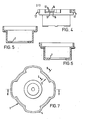
- the cap includes an outer sleeve 1 of plastics material, an inner sleeve 2 of plastics material, and means within the inner sleeve for relieving over or under pressure in the cooling system.
- the outer sleeve is provided with threads 3 for engaging the filler neck, but the threads are broken in the region of lobes 4, which lobes serve the dual purpose of making the cap easier to grip and providing a passage through which the cap is vented.
- the outer sleeve 1 is closed at the top, but is shaped to guide a venting button 5 in the centre.
- the inner sleeve 2 seats against the filler neck via a seal 6, and has an aperture 7 in the bottom which is closed by a seal member 8. Seal member 8 is compressed against spring 9 in the case of overpressure and disc 10 is sucked downwards from the
- venting takes place via the lobes 4 of the outer sleeve.
- the venting button 5 may be manually depressed to vent the cooling system before the cap is removed.
- the present invention is concerned with the means of securing together of the inner and outer sleeves 2,1.
- the inner sleeve is of stepped cylindrical form, the narrower part fitting within the filler neck and the wider part engaging with the outer sleeve.
- the wider part bears four integrally formed lugs indicated generally by the reference numeral 12.
- Each lug stands out from the surface of the inner member ( Figure 3).
- Each lug has an aperture 13 and a tag 14. In their free standing position, each tag projects outwardly from its respective lug. However, each tag is resiliently deflectable and can be pressed into the aperture 13 so that it does not protrude beyond the surface of the lug.
- the bottom surface 15 of the lug slopes in a circumferential direction.
- the outer sleeve in addition to features already described, is provided between the lobes 4 and beyond the threads 3, with sloping shoulders 16, the sloping being in a circumferential direction and the same inclination as that on the lower surface 15 of the lugs.
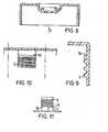
- the over and under pressure valve is inserted into the inner sleeve, and the inner sleeve is then pushed right to the bottom of the outer sleeve, taking care that the lugs 12 are aligned with the lobes 4.
- the inner sleeve is then rotated in a clockwise direction relative to the outer sleeve, and the tags 14 are resiliently deflected when they meet the cylindrical wall of the outer sleeve above the shoulders 16.
- each lug 12 rides up the co-operating sloping surface of the respective shoulders 16, and eventually the inner sleeve cannot be turned any further relative to the outer sleeve (this is shown in an exaggerated form in Figure 11). The inner sleeve accordingly cannot be advanced any further relative to the outer sleeve.
- the lugs are so shaped and positioned that the tags have come level with a lobe and have sprung outwardly as illustrated in Figure 2. Consequently, the inner sleeve cannot be turned in a reverse direction relative to the outer sleeve either. The inner and outer sleeves are therefore mechanically looked together.
- the lugs 12 could be provided on the outer sleeve and the shoulders 16 could be provided on the inner sleeve.
- other forms of valve means could be provided.
- other means to prevent relative rotation in the forward direction after the tags have sprung out could be provided in place of the inclined cam surface and cam followers.
- stop means comprising simple abutting surfaces could be provided, the abutting surfaces meeting when the tags have sprung out.
Landscapes
- Engineering & Computer Science (AREA)
- Chemical & Material Sciences (AREA)
- Combustion & Propulsion (AREA)
- Mechanical Engineering (AREA)
- General Engineering & Computer Science (AREA)
- Closures For Containers (AREA)
- Cooling, Air Intake And Gas Exhaust, And Fuel Tank Arrangements In Propulsion Units (AREA)
Applications Claiming Priority (2)
| Application Number | Priority Date | Filing Date | Title |
|---|---|---|---|
| GB08228497A GB2128595B (en) | 1982-10-06 | 1982-10-06 | Pressure cap |
| GB8228497 | 1982-10-06 |
Publications (2)
| Publication Number | Publication Date |
|---|---|
| EP0106524A2 true EP0106524A2 (de) | 1984-04-25 |
| EP0106524A3 EP0106524A3 (de) | 1984-12-27 |
Family
ID=10533412
Family Applications (1)
| Application Number | Title | Priority Date | Filing Date |
|---|---|---|---|
| EP83305322A Withdrawn EP0106524A3 (de) | 1982-10-06 | 1983-09-12 | Verschlussdeckel mit Vorrichtungen zum Ausgleichen von Über- oder Unterdrucken |
Country Status (4)
| Country | Link |
|---|---|
| EP (1) | EP0106524A3 (de) |
| JP (1) | JPS59134164A (de) |
| ES (1) | ES283292Y (de) |
| GB (1) | GB2128595B (de) |
Cited By (2)
| Publication number | Priority date | Publication date | Assignee | Title |
|---|---|---|---|---|
| CN103386883A (zh) * | 2013-07-31 | 2013-11-13 | 广西柳工机械股份有限公司 | 燃油箱盖 |
| WO2015157236A1 (en) * | 2014-04-11 | 2015-10-15 | Silgan White Cap LLC | Metal closure with low pressure engagement lugs |
Families Citing this family (2)
| Publication number | Priority date | Publication date | Assignee | Title |
|---|---|---|---|---|
| GB2174797B (en) * | 1985-05-02 | 1988-12-14 | Adwest Group P L C | Pressure relief/sealing caps |
| SE9500056D0 (sv) * | 1995-01-09 | 1995-01-09 | Broden Bengt Inge | Behållare för medicinska preparat |
Family Cites Families (3)
| Publication number | Priority date | Publication date | Assignee | Title |
|---|---|---|---|---|
| US3986634A (en) * | 1974-06-05 | 1976-10-19 | General Motors Corporation | Torque limiter mechanism |
| GB1529986A (en) * | 1976-08-12 | 1978-10-25 | Gen Motors Ltd | Closure caps |
| DE2752930A1 (de) * | 1977-11-26 | 1979-05-31 | Sueddeutsche Kuehler Behr | Verschlussteil fuer fuellstutzen von kuehler bzw. ausgleichsbehaelter in kuehlkreislaeufen von brennkraftmaschinen, insbesondere von kraftfahrzeugen, mit einem ueberdruck- und unterdruckventil |
-
1982
- 1982-10-06 GB GB08228497A patent/GB2128595B/en not_active Expired
-
1983
- 1983-09-12 EP EP83305322A patent/EP0106524A3/de not_active Withdrawn
- 1983-10-05 ES ES1983283292U patent/ES283292Y/es not_active Expired
- 1983-10-06 JP JP58186059A patent/JPS59134164A/ja active Pending
Cited By (4)
| Publication number | Priority date | Publication date | Assignee | Title |
|---|---|---|---|---|
| CN103386883A (zh) * | 2013-07-31 | 2013-11-13 | 广西柳工机械股份有限公司 | 燃油箱盖 |
| WO2015157236A1 (en) * | 2014-04-11 | 2015-10-15 | Silgan White Cap LLC | Metal closure with low pressure engagement lugs |
| US9694946B2 (en) | 2014-04-11 | 2017-07-04 | Silgan White Cap LLC | Metal closure with low pressure engagement lugs |
| US10364070B2 (en) | 2014-04-11 | 2019-07-30 | Silgan White Cap LLC | Metal closure with low pressure engagement lugs |
Also Published As
| Publication number | Publication date |
|---|---|
| ES283292Y (es) | 1986-04-01 |
| EP0106524A3 (de) | 1984-12-27 |
| GB2128595A (en) | 1984-05-02 |
| ES283292U (es) | 1985-06-16 |
| JPS59134164A (ja) | 1984-08-01 |
| GB2128595B (en) | 1986-02-12 |
Similar Documents
| Publication | Publication Date | Title |
|---|---|---|
| US4162021A (en) | Pressure-vacuum relief fuel tank cap with roll-over safety valve feature | |
| US4000828A (en) | Gas tank cap with roll-over valving | |
| US4165816A (en) | Vent cap | |
| US3938692A (en) | Pressure-vacuum relief fuel tank cap with roll-over safety valve feature | |
| US4091959A (en) | Gas cap | |
| US4561559A (en) | Fuel tank venting valve | |
| US4854471A (en) | Fuel cap | |
| US4887733A (en) | Pressure-release fuel cap | |
| US4040404A (en) | Fuel tank pressure-vacuum relief valve | |
| US4896789A (en) | Anti-leak fuel cap liner | |
| US5547099A (en) | Cover assembly for permitting access into a container without removal therefrom | |
| US3164288A (en) | Closure and valve construction | |
| US3913783A (en) | Safety closure cap with retaining feet | |
| US4528895A (en) | Piston for cylinder device | |
| EP0106524A2 (de) | Verschlussdeckel mit Vorrichtungen zum Ausgleichen von Über- oder Unterdrucken | |
| US20030234254A1 (en) | Vented fuel tank cap | |
| US5114035A (en) | Vehicle radiator cap | |
| US4113300A (en) | Filler connection for vehicles driven by internal combustion engines | |
| US5435454A (en) | Oil reservoir cap with concentric baffles | |
| US3769952A (en) | Installation for venting a fuel tank of a motor vehicle provided with expansion tank | |
| US4142648A (en) | Cap assembly for a fuel tank | |
| US3861557A (en) | Vent cap | |
| US4476995A (en) | Breather cap | |
| US3703245A (en) | Filler cap | |
| US20060138139A1 (en) | Anti-siphon fuel cap and filler tube assembly |
Legal Events
| Date | Code | Title | Description |
|---|---|---|---|
| PUAI | Public reference made under article 153(3) epc to a published international application that has entered the european phase |
Free format text: ORIGINAL CODE: 0009012 |
|
| AK | Designated contracting states |
Designated state(s): DE FR GB IT |
|
| PUAL | Search report despatched |
Free format text: ORIGINAL CODE: 0009013 |
|
| AK | Designated contracting states |
Designated state(s): DE FR GB IT |
|
| STAA | Information on the status of an ep patent application or granted ep patent |
Free format text: STATUS: THE APPLICATION IS DEEMED TO BE WITHDRAWN |
|
| 18D | Application deemed to be withdrawn |
Effective date: 19850828 |
|
| RIN1 | Information on inventor provided before grant (corrected) |
Inventor name: LARDNER, GRAHAM GERALD |