EP0106524A2 - A pressure cap - Google Patents
A pressure cap Download PDFInfo
- Publication number
- EP0106524A2 EP0106524A2 EP83305322A EP83305322A EP0106524A2 EP 0106524 A2 EP0106524 A2 EP 0106524A2 EP 83305322 A EP83305322 A EP 83305322A EP 83305322 A EP83305322 A EP 83305322A EP 0106524 A2 EP0106524 A2 EP 0106524A2
- Authority
- EP
- European Patent Office
- Prior art keywords
- sleeve
- pressure cap
- tag
- inner sleeve
- cooling system
- Prior art date
- Legal status (The legal status is an assumption and is not a legal conclusion. Google has not performed a legal analysis and makes no representation as to the accuracy of the status listed.)
- Withdrawn
Links
- 238000001816 cooling Methods 0.000 claims abstract description 15
- 239000004033 plastic Substances 0.000 claims abstract description 5
- 229920003023 plastic Polymers 0.000 claims abstract description 5
- 238000007789 sealing Methods 0.000 claims abstract description 3
- 239000000463 material Substances 0.000 claims description 4
- 239000000945 filler Substances 0.000 abstract description 7
- 238000013022 venting Methods 0.000 description 3
- 238000002485 combustion reaction Methods 0.000 description 2
- 230000000994 depressogenic effect Effects 0.000 description 1
- 230000009977 dual effect Effects 0.000 description 1
- 239000012530 fluid Substances 0.000 description 1
- -1 for example Substances 0.000 description 1
- 230000003993 interaction Effects 0.000 description 1
- XLYOFNOQVPJJNP-UHFFFAOYSA-N water Substances O XLYOFNOQVPJJNP-UHFFFAOYSA-N 0.000 description 1
Images

Classifications
-
- F—MECHANICAL ENGINEERING; LIGHTING; HEATING; WEAPONS; BLASTING
- F01—MACHINES OR ENGINES IN GENERAL; ENGINE PLANTS IN GENERAL; STEAM ENGINES
- F01P—COOLING OF MACHINES OR ENGINES IN GENERAL; COOLING OF INTERNAL-COMBUSTION ENGINES
- F01P11/00—Component parts, details, or accessories not provided for in, or of interest apart from, groups F01P1/00 - F01P9/00
- F01P11/02—Liquid-coolant filling, overflow, venting, or draining devices
- F01P11/0204—Filling
- F01P11/0209—Closure caps
- F01P11/0247—Safety; Locking against opening
-
- F—MECHANICAL ENGINEERING; LIGHTING; HEATING; WEAPONS; BLASTING
- F01—MACHINES OR ENGINES IN GENERAL; ENGINE PLANTS IN GENERAL; STEAM ENGINES
- F01P—COOLING OF MACHINES OR ENGINES IN GENERAL; COOLING OF INTERNAL-COMBUSTION ENGINES
- F01P11/00—Component parts, details, or accessories not provided for in, or of interest apart from, groups F01P1/00 - F01P9/00
- F01P11/02—Liquid-coolant filling, overflow, venting, or draining devices
- F01P11/0204—Filling
- F01P11/0209—Closure caps
- F01P11/0238—Closure caps with overpressure valves or vent valves
-
- F—MECHANICAL ENGINEERING; LIGHTING; HEATING; WEAPONS; BLASTING
- F01—MACHINES OR ENGINES IN GENERAL; ENGINE PLANTS IN GENERAL; STEAM ENGINES
- F01P—COOLING OF MACHINES OR ENGINES IN GENERAL; COOLING OF INTERNAL-COMBUSTION ENGINES
- F01P11/00—Component parts, details, or accessories not provided for in, or of interest apart from, groups F01P1/00 - F01P9/00
- F01P11/02—Liquid-coolant filling, overflow, venting, or draining devices
- F01P11/0204—Filling
- F01P11/0209—Closure caps
- F01P11/0247—Safety; Locking against opening
- F01P2011/0252—Venting before opening
Definitions
- This invention relates to pressure caps for vehicle cooling systems.
- the invention provides a pressure cap-for a vehicle cooling system, which comprises an outer sleeve having means for fitting to a neck of a cooling system, an inner sleeve having means for sealing against the neck and a pressure relief valve for relieving over and/or under pressure in the cooling system, at least one tag on one sleeve which tag is arranged so that, when the inner sleeve is inserted into the outer sleeve during assembly of the cap, the tag is resiliently deflected but springs back on , relative rotation in one direction of the sleeves to engage the other sleeve to prevent relative rotation in the reverse direction, and stop means to prevent further relative rotation of the sleeves in the said one direction after the relative rotation to release the tag has been completed.
- the tag or tags and the stop means form a simple means of attachment of the inner and outer sleeves of the pressure cap.
- the stop means comprises an inclined cam surface extending in a circumferential direction on one sleeve and a follower on the other sleeve which cam and follower co-operate to prevent the further relative movement.
- the tag projects, in its free-standing state, from a lug formed on one sleeve, the lug riding as cam follower on the inclined cam surface on the other sleeve.
- the combining of the tag with the cam follower means that it is only necessary to provide a sloping cam surface on the other sleeve.
- the lug including the tag can be moulded integrally with the rest of the sleeve, which is preferably made of plastics material.
- the tag is carried by the inner sleeve, and the inclined cam surface by the outer sleeve.
- the pressure cap is to be fitted to the filler neck of a radiator or an expansion tank of a cooling system for an internal combustion engine.
- the cap includes an outer sleeve 1 of plastics material, an inner sleeve 2 of plastics material, and means within the inner sleeve for relieving over or under pressure in the cooling system.
- the outer sleeve is provided with threads 3 for engaging the filler neck, but the threads are broken in the region of lobes 4, which lobes serve the dual purpose of making the cap easier to grip and providing a passage through which the cap is vented.
- the outer sleeve 1 is closed at the top, but is shaped to guide a venting button 5 in the centre.
- the inner sleeve 2 seats against the filler neck via a seal 6, and has an aperture 7 in the bottom which is closed by a seal member 8. Seal member 8 is compressed against spring 9 in the case of overpressure and disc 10 is sucked downwards from the
- venting takes place via the lobes 4 of the outer sleeve.
- the venting button 5 may be manually depressed to vent the cooling system before the cap is removed.
- the present invention is concerned with the means of securing together of the inner and outer sleeves 2,1.
- the inner sleeve is of stepped cylindrical form, the narrower part fitting within the filler neck and the wider part engaging with the outer sleeve.
- the wider part bears four integrally formed lugs indicated generally by the reference numeral 12.
- Each lug stands out from the surface of the inner member ( Figure 3).
- Each lug has an aperture 13 and a tag 14. In their free standing position, each tag projects outwardly from its respective lug. However, each tag is resiliently deflectable and can be pressed into the aperture 13 so that it does not protrude beyond the surface of the lug.
- the bottom surface 15 of the lug slopes in a circumferential direction.
- the outer sleeve in addition to features already described, is provided between the lobes 4 and beyond the threads 3, with sloping shoulders 16, the sloping being in a circumferential direction and the same inclination as that on the lower surface 15 of the lugs.
- the over and under pressure valve is inserted into the inner sleeve, and the inner sleeve is then pushed right to the bottom of the outer sleeve, taking care that the lugs 12 are aligned with the lobes 4.
- the inner sleeve is then rotated in a clockwise direction relative to the outer sleeve, and the tags 14 are resiliently deflected when they meet the cylindrical wall of the outer sleeve above the shoulders 16.
- each lug 12 rides up the co-operating sloping surface of the respective shoulders 16, and eventually the inner sleeve cannot be turned any further relative to the outer sleeve (this is shown in an exaggerated form in Figure 11). The inner sleeve accordingly cannot be advanced any further relative to the outer sleeve.
- the lugs are so shaped and positioned that the tags have come level with a lobe and have sprung outwardly as illustrated in Figure 2. Consequently, the inner sleeve cannot be turned in a reverse direction relative to the outer sleeve either. The inner and outer sleeves are therefore mechanically looked together.
- the lugs 12 could be provided on the outer sleeve and the shoulders 16 could be provided on the inner sleeve.
- other forms of valve means could be provided.
- other means to prevent relative rotation in the forward direction after the tags have sprung out could be provided in place of the inclined cam surface and cam followers.
- stop means comprising simple abutting surfaces could be provided, the abutting surfaces meeting when the tags have sprung out.
Abstract
A pressure cap for a vehicle cooling system consists of two plastic sleeves, the outer one 1 of which has threads 3,4 engaging a filler neck and the inner one 2 of which has a seal 6 for sealing against the filler neck. The inner sleeve contains the pressure relief valves.
The inner and outer sleeves are secured together by a simple mechanical means consisting of four lugs 12 provided at the top of the inner sleeve, each lug being provided with a resilient tag 14. During assembly, the inner sleeve is inserted in the outer sleeve with the lugs in alignment with lobes 4 in the outer sleeve. The inner sleeve is then rotated, and this resiliently deflects the tags 14 inwards. By the time that the inner sleeve has been rotated in a clockwise direction to the position shown in Figure 4, the tags are level with a lobe and can spring outwards and prevent reverse rotation of the inner sleeve. The parts are then locked together since an inclined circumferential cam surface and cam follower (not shown) prevents any further rotation of the inner sleeve In a clockwise direction relative to the outer sleeve.
Description
- This invention relates to pressure caps for vehicle cooling systems.
- It is normal practise for vehicles incorporating liquid-cooled internal combustion engines to employ a pressure cap which is usually located on a filler neck either on the radiator or on an expansion tank. Such pressure caps commonly employ pressure relief valves which permit the passage of fluid, for example, air or water vapour, when the pressure exceeds a given under- or a given over- pressure.
- The invention provides a pressure cap-for a vehicle cooling system, which comprises an outer sleeve having means for fitting to a neck of a cooling system, an inner sleeve having means for sealing against the neck and a pressure relief valve for relieving over and/or under pressure in the cooling system, at least one tag on one sleeve which tag is arranged so that, when the inner sleeve is inserted into the outer sleeve during assembly of the cap, the tag is resiliently deflected but springs back on , relative rotation in one direction of the sleeves to engage the other sleeve to prevent relative rotation in the reverse direction, and stop means to prevent further relative rotation of the sleeves in the said one direction after the relative rotation to release the tag has been completed.
- The tag or tags and the stop means form a simple means of attachment of the inner and outer sleeves of the pressure cap.
- Advantageously the stop means comprises an inclined cam surface extending in a circumferential direction on one sleeve and a follower on the other sleeve which cam and follower co-operate to prevent the further relative movement. Preferably, the tag projects, in its free-standing state, from a lug formed on one sleeve, the lug riding as cam follower on the inclined cam surface on the other sleeve. The combining of the tag with the cam follower means that it is only necessary to provide a sloping cam surface on the other sleeve. Conveniently, the lug including the tag can be moulded integrally with the rest of the sleeve, which is preferably made of plastics material.
- Advantageously the tag is carried by the inner sleeve, and the inclined cam surface by the outer sleeve.
- A pressure cap for a vehicle cooling system will now be described by way of example with reference to the accompanying drawings, in which:
- Figure 1 is a section through the cap taken on lines 1-1 of Figure 2;
- Figure 2 is a bottom plan view of the cap looking along the line 2 in Figure 1;
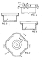
- Figure 3 is a top plan view of the inner sleeve of the cap;
- Figure 4 is a front view of the sleeve shown in Figure 3;
- Figure 5 is a section taken through the lines 5-5 in Figure 3;
- Figure 6 is a section through the lines 6-6 in Figure 3;
- Figure 7 is a bottom plan view..of the outer sleeve looking along line 7 in Figure 8;
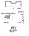
- Figure 8 is a section through lines 8-8 in Figure 7;
- Figure 9 is a section through lines 9-9 in Figure 7 but on an enlarged scale;
- Figure 10 is a view in the direction of
arrow 10 in Figure 7; and - Figure 11 shows in an exaggerated manner the interaction of a lug with the cam surface.
- The pressure cap is to be fitted to the filler neck of a radiator or an expansion tank of a cooling system for an internal combustion engine.
- Referring to Figures 1 and 2, the cap includes an outer sleeve 1 of plastics material, an inner sleeve 2 of plastics material, and means within the inner sleeve for relieving over or under pressure in the cooling system.
- The outer sleeve is provided with
threads 3 for engaging the filler neck, but the threads are broken in the region of lobes 4, which lobes serve the dual purpose of making the cap easier to grip and providing a passage through which the cap is vented. The outer sleeve 1 is closed at the top, but is shaped to guide aventing button 5 in the centre. - The inner sleeve 2 seats against the filler neck via a seal 6, and has an aperture 7 in the bottom which is closed by a seal member 8. Seal member 8 is compressed against spring 9 in the case of overpressure and
disc 10 is sucked downwards from the - seal member 8 against spring 11 in the case of under pressure. In each case venting takes place via the lobes 4 of the outer sleeve. The
venting button 5 may be manually depressed to vent the cooling system before the cap is removed. These. features of the cap are described and claimed in our co-pending application number 82 17975. - The present invention is concerned with the means of securing together of the inner and outer sleeves 2,1.
- Referring to figure 3 to 6, the inner sleeve is of stepped cylindrical form, the narrower part fitting within the filler neck and the wider part engaging with the outer sleeve. The wider part bears four integrally formed lugs indicated generally by the
reference numeral 12. Each lug stands out from the surface of the inner member (Figure 3). Each lug has anaperture 13 and atag 14. In their free standing position, each tag projects outwardly from its respective lug. However, each tag is resiliently deflectable and can be pressed into theaperture 13 so that it does not protrude beyond the surface of the lug. Thebottom surface 15 of the lug (as seen in Figure 4) slopes in a circumferential direction. - Referring to Figure 7 to 10, the outer sleeve, in addition to features already described, is provided between the lobes 4 and beyond the
threads 3, with slopingshoulders 16, the sloping being in a circumferential direction and the same inclination as that on thelower surface 15 of the lugs. - To assemble the pressure cap, the over and under pressure valve is inserted into the inner sleeve, and the inner sleeve is then pushed right to the bottom of the outer sleeve, taking care that the
lugs 12 are aligned with the lobes 4. Referring to Figure 2, the inner sleeve is then rotated in a clockwise direction relative to the outer sleeve, and thetags 14 are resiliently deflected when they meet the cylindrical wall of the outer sleeve above theshoulders 16. As the inner sleeve is rotated, thebottom surface 15 of eachlug 12 rides up the co-operating sloping surface of therespective shoulders 16, and eventually the inner sleeve cannot be turned any further relative to the outer sleeve (this is shown in an exaggerated form in Figure 11). The inner sleeve accordingly cannot be advanced any further relative to the outer sleeve. - Just before this point has been reached, the lugs are so shaped and positioned that the tags have come level with a lobe and have sprung outwardly as illustrated in Figure 2. Consequently, the inner sleeve cannot be turned in a reverse direction relative to the outer sleeve either. The inner and outer sleeves are therefore mechanically looked together.
- If desired the
lugs 12 could be provided on the outer sleeve and theshoulders 16 could be provided on the inner sleeve. Also, other forms of valve means could be provided. Furthermore, other means to prevent relative rotation in the forward direction after the tags have sprung out could be provided in place of the inclined cam surface and cam followers. For example, stop means comprising simple abutting surfaces could be provided, the abutting surfaces meeting when the tags have sprung out.
Claims (11)
1. A pressure cap for a vehicle cooling system, which comprises an outer sleeve having means for fitting to a neck of a cooling system, an inner sleeve having means for sealing against the neck and a pressure relief valve for relieving over and/or under pressure in the cooling system, at least one tag on one sleeve which tag is arranged so that, when the inner sleeve is inserted into the outer sleeve during. assembly of the cap, the tag is resiliently deflected but springs back on relative rotation in one direction of the sleeves to engage the other sleeve to prevent relative rotation in the reverse direction, and stop means to prevent further relative rotation of the sleeves in the said one direction after the relative rotation to release the tag has been completed.
2. A pressure cap as claimed in claim 1, wherein the stop means comprises an inclined cam surface extending in a circumferential direction on one sleeve and a follower on the other sleeve which cam and follower co-operate to prevent the. further relative rotation of the sleeves.
3. A pressure cap as claimed in claim 2, wherein the tag projects, in its free-standing state, from a lug formed on one sleeve, the lug riding as cam follower on an inclined cam surface on the other sleeve.
4. A pressure cap as claimed in claim 3, wherein the part of the lug that rides on the inclined cam surface has the same inclination as the cam surface.
5. A pressure cap as claimed in claim 3 or claim 4, wherein the tag is carried by the inner sleeve, and the inclined cam surface by the outer sleeve..
6. A pressure cap as claimed in claim 5, wherein the outer sleeve has screw-threads for fitting to the neck of the cooling system, and the inclined cam surface is positioned beyond that threaded portion.
7. A pressure cap as claimed in any one of claims 1 to 6, wherein the sleeves are made of plastics material.
8. A pressure cap as claimed in claim 7, wherein the tag is formed integrally with one of the sleeves.
9. A pressure cap substantially as hereinbefore described with reference to, and as shown in, the accompanying drawings.
10. A vehicle cooling system having a pressure cap as claimed in any one of claims 1 to 9.
11. A vehicle having a cooling system as claimed in claim 10.
Applications Claiming Priority (2)
| Application Number | Priority Date | Filing Date | Title |
|---|---|---|---|
| GB08228497A GB2128595B (en) | 1982-10-06 | 1982-10-06 | Pressure cap |
| GB8228497 | 1982-10-06 |
Publications (2)
| Publication Number | Publication Date |
|---|---|
| EP0106524A2 true EP0106524A2 (en) | 1984-04-25 |
| EP0106524A3 EP0106524A3 (en) | 1984-12-27 |
Family
ID=10533412
Family Applications (1)
| Application Number | Title | Priority Date | Filing Date |
|---|---|---|---|
| EP83305322A Withdrawn EP0106524A3 (en) | 1982-10-06 | 1983-09-12 | A pressure cap |
Country Status (4)
| Country | Link |
|---|---|
| EP (1) | EP0106524A3 (en) |
| JP (1) | JPS59134164A (en) |
| ES (1) | ES283292Y (en) |
| GB (1) | GB2128595B (en) |
Cited By (2)
| Publication number | Priority date | Publication date | Assignee | Title |
|---|---|---|---|---|
| CN103386883A (en) * | 2013-07-31 | 2013-11-13 | 广西柳工机械股份有限公司 | Fuel tank cover |
| WO2015157236A1 (en) * | 2014-04-11 | 2015-10-15 | Silgan White Cap LLC | Metal closure with low pressure engagement lugs |
Families Citing this family (2)
| Publication number | Priority date | Publication date | Assignee | Title |
|---|---|---|---|---|
| GB2174797B (en) * | 1985-05-02 | 1988-12-14 | Adwest Group P L C | Pressure relief/sealing caps |
| SE9500056D0 (en) * | 1995-01-09 | 1995-01-09 | Broden Bengt Inge | Containers for medical preparations |
Citations (3)
| Publication number | Priority date | Publication date | Assignee | Title |
|---|---|---|---|---|
| USB516032I5 (en) * | 1974-06-05 | 1976-01-27 | ||
| FR2361535A1 (en) * | 1976-08-12 | 1978-03-10 | Gen Motors Ltd | PERFECTED RADIATOR CAP |
| FR2410129A1 (en) * | 1977-11-26 | 1979-06-22 | Sueddeutsche Kuehler Behr | Vehicle radiator filling cap - has valve plate working with sealing disc and acting as spring counter bearing |
-
1982
- 1982-10-06 GB GB08228497A patent/GB2128595B/en not_active Expired
-
1983
- 1983-09-12 EP EP83305322A patent/EP0106524A3/en not_active Withdrawn
- 1983-10-05 ES ES1983283292U patent/ES283292Y/en not_active Expired
- 1983-10-06 JP JP58186059A patent/JPS59134164A/en active Pending
Patent Citations (3)
| Publication number | Priority date | Publication date | Assignee | Title |
|---|---|---|---|---|
| USB516032I5 (en) * | 1974-06-05 | 1976-01-27 | ||
| FR2361535A1 (en) * | 1976-08-12 | 1978-03-10 | Gen Motors Ltd | PERFECTED RADIATOR CAP |
| FR2410129A1 (en) * | 1977-11-26 | 1979-06-22 | Sueddeutsche Kuehler Behr | Vehicle radiator filling cap - has valve plate working with sealing disc and acting as spring counter bearing |
Cited By (4)
| Publication number | Priority date | Publication date | Assignee | Title |
|---|---|---|---|---|
| CN103386883A (en) * | 2013-07-31 | 2013-11-13 | 广西柳工机械股份有限公司 | Fuel tank cover |
| WO2015157236A1 (en) * | 2014-04-11 | 2015-10-15 | Silgan White Cap LLC | Metal closure with low pressure engagement lugs |
| US9694946B2 (en) | 2014-04-11 | 2017-07-04 | Silgan White Cap LLC | Metal closure with low pressure engagement lugs |
| US10364070B2 (en) | 2014-04-11 | 2019-07-30 | Silgan White Cap LLC | Metal closure with low pressure engagement lugs |
Also Published As
| Publication number | Publication date |
|---|---|
| GB2128595B (en) | 1986-02-12 |
| JPS59134164A (en) | 1984-08-01 |
| ES283292Y (en) | 1986-04-01 |
| ES283292U (en) | 1985-06-16 |
| EP0106524A3 (en) | 1984-12-27 |
| GB2128595A (en) | 1984-05-02 |
Similar Documents
| Publication | Publication Date | Title |
|---|---|---|
| US4162021A (en) | Pressure-vacuum relief fuel tank cap with roll-over safety valve feature | |
| US4000828A (en) | Gas tank cap with roll-over valving | |
| US4165816A (en) | Vent cap | |
| US3938692A (en) | Pressure-vacuum relief fuel tank cap with roll-over safety valve feature | |
| CA1070644A (en) | Torque-limiting device | |
| US4091955A (en) | Plastic filler neck cap | |
| US4091959A (en) | Gas cap | |
| US4561559A (en) | Fuel tank venting valve | |
| US4854471A (en) | Fuel cap | |
| US4896789A (en) | Anti-leak fuel cap liner | |
| US5547099A (en) | Cover assembly for permitting access into a container without removal therefrom | |
| US4040404A (en) | Fuel tank pressure-vacuum relief valve | |
| US4440308A (en) | Fuel cap valve structure | |
| US3913783A (en) | Safety closure cap with retaining feet | |
| EP0106524A2 (en) | A pressure cap | |
| US20030234254A1 (en) | Vented fuel tank cap | |
| CA1040559A (en) | Tank filler neck | |
| US5435454A (en) | Oil reservoir cap with concentric baffles | |
| US3769952A (en) | Installation for venting a fuel tank of a motor vehicle provided with expansion tank | |
| US5114035A (en) | Vehicle radiator cap | |
| US4476995A (en) | Breather cap | |
| US4280529A (en) | Vented fuel tank cap | |
| EP0119174A1 (en) | Double-acting breather valve, particularly for fuel tanks of motor vehicles | |
| EP0097443A1 (en) | Pressure cap | |
| US4360122A (en) | Tank cap having sequential engagement and disengagement |
Legal Events
| Date | Code | Title | Description |
|---|---|---|---|
| PUAI | Public reference made under article 153(3) epc to a published international application that has entered the european phase |
Free format text: ORIGINAL CODE: 0009012 |
|
| AK | Designated contracting states |
Designated state(s): DE FR GB IT |
|
| PUAL | Search report despatched |
Free format text: ORIGINAL CODE: 0009013 |
|
| AK | Designated contracting states |
Designated state(s): DE FR GB IT |
|
| STAA | Information on the status of an ep patent application or granted ep patent |
Free format text: STATUS: THE APPLICATION IS DEEMED TO BE WITHDRAWN |
|
| 18D | Application deemed to be withdrawn |
Effective date: 19850828 |
|
| RIN1 | Information on inventor provided before grant (corrected) |
Inventor name: LARDNER, GRAHAM GERALD |