EP0105922B1 - Wärmeaustauscher mit schwimmenden platten - Google Patents
Wärmeaustauscher mit schwimmenden platten Download PDFInfo
- Publication number
- EP0105922B1 EP0105922B1 EP83901769A EP83901769A EP0105922B1 EP 0105922 B1 EP0105922 B1 EP 0105922B1 EP 83901769 A EP83901769 A EP 83901769A EP 83901769 A EP83901769 A EP 83901769A EP 0105922 B1 EP0105922 B1 EP 0105922B1
- Authority
- EP
- European Patent Office
- Prior art keywords
- plate
- plates
- planes
- resilient
- stack
- Prior art date
- Legal status (The legal status is an assumption and is not a legal conclusion. Google has not performed a legal analysis and makes no representation as to the accuracy of the status listed.)
- Expired
Links
Images


Classifications
-
- F—MECHANICAL ENGINEERING; LIGHTING; HEATING; WEAPONS; BLASTING
- F28—HEAT EXCHANGE IN GENERAL
- F28F—DETAILS OF HEAT-EXCHANGE AND HEAT-TRANSFER APPARATUS, OF GENERAL APPLICATION
- F28F3/00—Plate-like or laminated elements; Assemblies of plate-like or laminated elements
- F28F3/08—Elements constructed for building-up into stacks, e.g. capable of being taken apart for cleaning
- F28F3/083—Elements constructed for building-up into stacks, e.g. capable of being taken apart for cleaning capable of being taken apart
-
- F—MECHANICAL ENGINEERING; LIGHTING; HEATING; WEAPONS; BLASTING
- F28—HEAT EXCHANGE IN GENERAL
- F28D—HEAT-EXCHANGE APPARATUS, NOT PROVIDED FOR IN ANOTHER SUBCLASS, IN WHICH THE HEAT-EXCHANGE MEDIA DO NOT COME INTO DIRECT CONTACT
- F28D9/00—Heat-exchange apparatus having stationary plate-like or laminated conduit assemblies for both heat-exchange media, the media being in contact with different sides of a conduit wall
- F28D9/0031—Heat-exchange apparatus having stationary plate-like or laminated conduit assemblies for both heat-exchange media, the media being in contact with different sides of a conduit wall the conduits for one heat-exchange medium being formed by paired plates touching each other
- F28D9/0037—Heat-exchange apparatus having stationary plate-like or laminated conduit assemblies for both heat-exchange media, the media being in contact with different sides of a conduit wall the conduits for one heat-exchange medium being formed by paired plates touching each other the conduits for the other heat-exchange medium also being formed by paired plates touching each other
-
- F—MECHANICAL ENGINEERING; LIGHTING; HEATING; WEAPONS; BLASTING
- F28—HEAT EXCHANGE IN GENERAL
- F28D—HEAT-EXCHANGE APPARATUS, NOT PROVIDED FOR IN ANOTHER SUBCLASS, IN WHICH THE HEAT-EXCHANGE MEDIA DO NOT COME INTO DIRECT CONTACT
- F28D9/00—Heat-exchange apparatus having stationary plate-like or laminated conduit assemblies for both heat-exchange media, the media being in contact with different sides of a conduit wall
- F28D9/0062—Heat-exchange apparatus having stationary plate-like or laminated conduit assemblies for both heat-exchange media, the media being in contact with different sides of a conduit wall the conduits for one heat-exchange medium being formed by spaced plates with inserted elements
-
- F—MECHANICAL ENGINEERING; LIGHTING; HEATING; WEAPONS; BLASTING
- F28—HEAT EXCHANGE IN GENERAL
- F28F—DETAILS OF HEAT-EXCHANGE AND HEAT-TRANSFER APPARATUS, OF GENERAL APPLICATION
- F28F2230/00—Sealing means
-
- F—MECHANICAL ENGINEERING; LIGHTING; HEATING; WEAPONS; BLASTING
- F28—HEAT EXCHANGE IN GENERAL
- F28F—DETAILS OF HEAT-EXCHANGE AND HEAT-TRANSFER APPARATUS, OF GENERAL APPLICATION
- F28F2240/00—Spacing means
-
- F—MECHANICAL ENGINEERING; LIGHTING; HEATING; WEAPONS; BLASTING
- F28—HEAT EXCHANGE IN GENERAL
- F28F—DETAILS OF HEAT-EXCHANGE AND HEAT-TRANSFER APPARATUS, OF GENERAL APPLICATION
- F28F2250/00—Arrangements for modifying the flow of the heat exchange media, e.g. flow guiding means; Particular flow patterns
- F28F2250/10—Particular pattern of flow of the heat exchange media
- F28F2250/102—Particular pattern of flow of the heat exchange media with change of flow direction
Definitions
- the present invention relates to plate type exchangers and more specifically to a new method of mounting exchanger plates, without welding, within an enclosing frame.
- the exchanger of the present invention is primarily intended for but not limited to applications in the field of heat recovery, e.g., by exchanging heat between a hot stream leaving a process and a cold stream entering the process.
- a heat exchanger according to the present invention can be employed as an air preheater for furnaces, boilers, incinerators, shale oil retorting and the like.
- the two fluids are usually gases, the temperature difference is not large and the allowable pressure drop is small. These conditions usually lead to the requirement of a large heat exchange surface.
- the gases are usually corrosive, poisonous or explosive when mixed, the heat exchanger must present good corrosion resistance and good sealing of the two streams.
- the quality of the heat recovered is usually low, the heat exchanger must be sufficiently inexpensive to justify the cost of the investment.
- FR-A-1 470 506 and GB-A-2 041 190 disclose heat exchangers including a plate block providing alternating cross-flow channels for heat exchange between two fluid streams and comprising a stack of consecutive, parallel, generally rectangular plates mounted within an enclosing frame.
- the block includes corrugated metal strips disposed between consecutive plates as pressure-distributing and pressure-transmission means.
- US-A-4 308 915 discloses plate block heat exchangers in which consecutive plates of the block are separated from each other to rigid separators.
- the present invention concerns a heat- exchanger plate block providing alternating cross-flow channels for heat exchange between two fluid streams and comprising a stack of consecutive, spaced, parallel, generally rectangular plates (11) mounted within an enclosing frame having generally rectangular end walls (12) parallel to the plates and corner posts (14) extending between and joining corners of the end walls, said plate block including resilient separators between said plates to render the stack of plates resiliently compressible as a unit in a direction normal to the planes of the plates, characterised in that each separator comprises an elongated, resilient strip (26, 116, 164) elastically compressible through its thickness, and a rigid spacer (25, 117) (170 and 172 and 174) said strip being in operative contact with a plate and said rigid spacer being disposed between and in operative contact with said resilient strip and the next consecutive plate.
- the end walls and corner posts desirably compress the stack of plates sufficiently to restrain the plates from gross movement in their planes, but the compression is limited to allow for further compression of the stack to enable the stack to internally absorb growth due to thermal expansion in the direction normal to the plane.
- resilient corner spacers spacing corners of the plates from adjacent corner posts to accommodate growth of the plates due to thermal expansion in a direction parallel to their planes.
- the plate block preferably includes supportive ribs extending across and between the plates, the ribs on opposite sides of each plate lying at right angles to each other.
- the ribs lying against similarly facing surfaces of alternating plates desirably are parallel and are positioned identically with respect to edges of the plates. That is, the ribs lie in spaced planes that are normal to the planes of the plates and that intersect each other at right angles with the intersection extending normal to the planes of the plates.
- the ribs serve to maintain spacing between the plates and, when full contact between the ribs and the plates occurs under such extreme circumstances, the criss-crossed ribs form, with the plates, a series of structurally supportive columns extending in a direction normal to the planes of the plates to support the plates against warping or other gross movement.
- the plate of the plate block is one which is generally rectangular and having two opposed edges each having a portion extending in the same direction generally normal to the plane of the plate and terminating in a flange extending outwardly and parallel to the plane of the plate.
- the remaining opposed edges of the plate are provided with upwardly bent portions, and, desirably, the length of the latter portions is less than the maximum length of the plates taken in the same direction.
- a further embodiment of the invention is characterised in that the plates are provided with a plurality of elongated dimples, the dimples of each plate extending closely adjacent the confronting surface of an adjacent plate and the dimples formed in consecutive plates being at right angles and staddling each other.
- the dimples in alternating plates are identically positioned.
- the aligned and criss-crossed dimples in consecutive plates lie in planes that intersect along lines normal to the planes of the plates.
- the dimples and plates coact to form structurally supportive columns extending normally of the planes of the plates to restrain buckling or warping of the plates.
- the elongated dimples preferably are formed with their longest dimension in the direction of the intended fluid flow. The longest dimension of each dimple substantially exceeds the shortest dimensions of adjacent dimples in adjacent plates.
- the exchanger utilizes that exchange surfaces of plane parallel plates made of corrosion resistant material, the plates forming a pattern of crossflow channels. Pressure differentials between fluids is compensated by means of spacers, e.g., ribs or dimples, placed inside the channels. Sealing of the cross- flow channels with respect to the two streams is realized by pressing adjacent plate edges resiliently toward one another with the aid of a rigid frame. Desirably, each plate is provided with resilient supports which permit free expansion in all directions while maintaining adequate sealing. That is, each plate virtually floats within resilient fixtures. This unique "floating plate” concept further allows economic utilization of expensive plate materials such as high alloy metals which can be employed as thin sheet or even frail materials such as ceramic or glass.
- the corners of the plates preferably are not notched or cut-away but rather are full; the plates, in plan view, desirably are substantially perfect rectangles.
- the heat exchanger comprises one or more blocks of rectangular exchanger plates, the plates being assembled in such manner as to provide in each block a pattern of crossflow channels for the two fluid streams involved in the heat exchange process.
- the heat exchange surfaces are essentially plane rectangles and are made preferably of corrosion resistant material such as metal alloys, ceramic, glass or the like.
- the thickness of said exchanger plates is selected with consideration given to material strength and corrosion resistance, and is made as small as possible.
- a plate block is formed by stacking together a plurality of exchanger plates, separating said exchanger plates from each other by a system of at least partially resilient plate separators and enclosing the thus formed assembly in a rigid metal frame.
- the frame also serves to compress the plate stack such that the edges of adjacent plates are pressed toward each other to provide a good seal.
- each plate is supported elastically and essentially independently from adjacent plates; each plate floats substantially freely within resilient, fixtures.
- a stack of floating plates is realized by placing resilient edge separators on two opposing edges of each plate and rigid edge separators on the remaining two edges. The resilient and rigid separators are normally staggered by 90° for each two adjacent plates.
- a plate stack is thus realized which is compressible in a direction perpendicular to the planes of the plates.
- the thus formed compressible plate stack is compressed by the frame to achieve tight assembly; yet, sufficient expansion allowance is provided to accommodate the expected thermal expansion during use. In this manner, thermal expansion is compensated locally by small displacement of each plate without cumulative large scale movement, and the number of plates in a stack can be made arbitrarily large.
- spacers are placed to help support the plates against pressure differences of the two streams.
- the spacers are placed such as to not obstruct the fluid flow in the corresponding channel and are in sufficient number such that the pressure force on a free plate span (between spacers) does not cause unduly large stresses within the plate.
- the spacers can be provided, e.g., in the form of beams affixed onto crossbars placed in the inlet and outlet areas of each channel. Alternatively the spacers can be formed integral with the plate by stamping on other affixation procedures.
- the enclosing frame of a plate stack includes four corner posts and two end walls.
- the material is preferably metallic.
- the end walls are positioned parallel to the exchanger plates and at the two ends of the plate stack, and are connected to the four corner posts desirably by bolting.
- the frame also serves to support the weight of the plate stack.
- a resilient seal is placed between each corner post and the corresponding corner portion of the plate stack, thus sealing the two streams from each other while allowing free thermal expansion of each plate in its own plane.
- An essentially rectangular frame is thus achieved which envelopes the plate stack to form a plate block.
- Flanging areas provided with bolt holes are also provided by rims of the rectangular frame for connection of the plate blocks to each other and to external duct work.
- the plate block as described can be used singly as a single pass crossflow heat exchanger or, it can be used singly and in conjunction with stream dividers as a multiple pass crossflow-counterflow heat exchanger or again, it can be connected to similar blocks to form a multipass crossflow-counterflow heat exchanger. Other combinations of flow patterns are also possible.
- a heat exchanger is thus achieved which provides good separation of the two fluid streams, and is free from leaks to the environment.
- the floating plate exchanger has a small bulk volume, reduced weight and reduced pressure drop. Clogging by soot from combustion gases does not constitute a problem with the present exchanger since there are no narrow passages and soot can be removed by conventional sootblowers.
- Figures 4 and 6 are included to facilitate general description of the invention. However, although those two Figures disclose resilient separators, neither of those separators is according to the invention in that they do not include a resilient strip elastically compressible through its thickness.
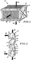
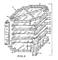
- the plate block (10) is principally composed of a plurality of exchanger plates (11) in an enclosing frame which generally comprises end walls (12) and corner posts (14) ( Figures 1, 3 and 8).
- Plate block (10) can be employed singly to form a crossflow exchanger ( Figure 1) or, in combination with other plate blocks (10) to form a crossflow-counterflow exchanger ( Figure 2).
- a single plate block (10) can also form a crossflow-counterflow exchanger by making use of stream dividers (33) to direct the flow ( Figure 3).
- a stream divider (33) may be affixed to two adjacent support channels (14) and to one of the exchanger plates (11). In the exchanger thus achieved, heat can be transferred between two fluid streams (80) and (90) which are generally at different pressures and flow through said exchanger separately and in a crossflow manner.
- the exchanger plates (11) are disposed parallel to each other in a plate stack (30) through the intermediary of a number of spacers (22), rigid edge separators (20) and elastic edge separators (21). The thus formed assembly is then tightly enclosed between the two end walls (12) ( Figure 1) which are bolted or otherwise affixed to the four corner posts (14).
- the exchanger plates (11) are essentially rectangular in shape and can be made of metal sheet, ceramic plate, glass plate or other material.
- the exchanger plates (11) thus form a number of parallel flow channels (28) through which fluids (80) and (90) flow.
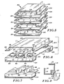
- fluid edge separators (20) are employed which are essentially rigid bars disposed at two opposing edges of each plate and staggered sequentially through 90°.
- the rigid edge separators (20) can be provided as detachable components of the plate stack (30) as shown in Figure 4.
- the rigid edge separator (20) can be formed as a fold (20) of the exchanger plate (11) as shown in Figure 5.
- said edge of the exchanger plate (11) is first folded 90° forward (normal to the plane of the plate) to form a rigid edge separator (20) and then folded 90° backward (outwardly and parallel to the plane of the plate) to from plate edge contact area or flange (24).
- exchanger plate configurations can be employed in the invention.
- One configuration is simply a plane rectangle as shown in Figure 4. This type is preferable with frail plate materials such as ceramic or glass.
- Another type is a rectangular plate wtih folded opposing edges as described above and as shown in Figures 5, 6, 7 and 8. This type is preferred with metal plates. It presents the advantages of providing a recessed space which can be used for the placement of crossbar (25) in such a way that it does not constitute an obstacle to fluid flow.
- a recessed space such as formed by the folded plates may also be realized with plane rectangular plates by recessing the rigid edge separators (20) and correspondingly trimming the plate size. The last arrangement is not pursued further in this description of a preferred embodiment.
- each exchanger plate (11) is supported by elastic edge separators (21) which are formed of a subasssm- bly consisting of crossbar (25) and springs (26).
- Crossbar (25) is essentially a rigid bar extending the entire length of the corresponding plate edge.
- Springs (26) can be provided in a variety of forms of which two are selected for the purpose of typifying this preferred embodiment.
- said elastic edge separator consists of the crossbar (25) on top of which a number of leaf springs (26) are affixed by notching or other procedure.
- Leaf springs (26) are compressed between the crossbar (25) and the plate edge above it.
- FIG. 7 Another preferred form is shown in Figure 7 in which a resilient strip (26) is placed under the crossbar (25) and edge spacers (32) are affixed on top of crossbar (25). Edge spacers (32) can be simply provided by the extended ends of the spacers or ribs (22). The strip (26) is compressed between crossbar (25) and the plate edge under it.
- the compressible, resilient strip (26) plays the role of a spring and, in this specific embodiment is not relied upon for the purpose of sealing.
- the strip (26) can be formed of ceramic fiber, wire mesh or other materials, and preferably extends through the length and width of the flange (24).
- the principal role of the resilient edge separator (21) ( Figure 4) is to absorb locally the differential thermal expansion between the plate stack and the enclosing frame. Another role of this separator is to aid the sealing of flow channels by pressing the plate edge contact areas (24) of two adjacent plates against each other.
- the dimension of the resilient edge separator (21) in the direction perpendicular to the exchanger plate plane is somewhat larger than the corresponding dimension of the rigid edge separator (20) and that of the spacers (22). Then, upon warming up, edge separators (20) and spacers (22) thermally expand while springs (26) are compressed.
- the natural flexibility of the exchanger plate helps maintain a good seal along the plate edge contact areas 24 at all temperatures, with only very small local displacements.
- the local absorption of the thermal growth by the resilient edge separators (21) is an important feature of the present invention.
- the cumulative thermal growth can be appreciable and can lead to unacceptably large stresses in the plate stack and the enclosing frame.
- springs (26) the pushing force on the end walls (12) depends upon the strength of the springs, which can be controlled by design.
- each flow channel (28) contains a plurality of spacers or ribs (22) with a width (measured normal to the planes of the plates) approximately equal to that of the flow channel (between plates).
- Spacers (22) can be realized in the form of detachable beams affixed to the crossbars (25) by notching or other equivalent procedure, as shown in Figures 4, 6 and 7.
- spacers (22) may be formed in a variety of shapes from the exchanger plate itself. Spacers (22) serve generally to reinforce the composite structure and help support the exchanger plates (11) against the pressure difference of the two streams.
- the plate stack as described above is placed inside the enclosing frame in close contact with the end walls (12) and with sufficient clearance allowed between the corners (34) of the plate stack ( Figures 8 and 9) and the corner posts (14) to accommodate thermal growth of the exchanger plates in their planes.
- the resilient seal (23) which can be a ceramic fiber packing or other packing with sufficient resiliency and adequate sealing properties.
- a manifold for the distribution of the two fluids at the inlets and outlets of plate block (10) are also afforded.
- a manifold can be viewed as being comprised of two adjacent corner posts (14) and the rims of the two end walls (12), the rigid edge separators (20) providing closure of part of the flow channels (28) and the elastic edge separators (21) providing fluid admission openings on the remaining flow channels (28).
- the end walls (12) and corner posts (14) also present bolt holes along their rims.
- the frame assembly bolt holes (16) serve to admit bolts for connecting the end walls (12) to the four corner posts (14).
- the block connecting bolt holes (15) serve to admit bolts for connecting blocks to each other and to the external duct work (31) ( Figure 2).
- Figure 2 depicts a heat exchanger composed of four plate blocks (10), providing one flow pass for fluid (80) and four flow passes for fluid (90). Fluid (80) may be stack flue gas and fluid (90) may be air.
- the turns (17) in the duct work serve to direct the air flow through the four blocks in series.
- Sootblowers 19 of known design may be installed between the blocks as depicted. With clean flue gas, sootblowers (19) and block connectors (18) can be omitted.
- the exchanger plates (11) are rectangular in shape and are typified as being made of stainless steel sheet. Two opposing edges of each plate are folded as described above to realise the rigid edge separators (20).
- the spacers (22) and the crossbars (25) may be formed of stainless steel plate by folding to form appropriately shaped hollow beams.
- the various frame components may be made of thick carbon steel plate and of the general shape presented in the drawings.
- the assembly of plate block (10) is then commenced by building a plate stack on one of the end walls (12), the latter serving as a building base. Plates are placed in the stack one by one and alternately 90° staggered.
- the crossbars (25), springs (26) and spacers (22) are placed before adding the next plate.
- the other end wall (12) is placed on top of the stack. Subsequently the stack is compressed between the two end walls (12) by means of clamps placed around the rim of the end walls to the limit of resilient compression, and the end walls are then moved apart a small distance to afford the stack a measure of resilient compressibility.
- the corner posts are positioned with the resilient corner seals (23) in place and the frame assembly bolts (16) are tightened.
- the plate block can now be tilted into the normal position with the exchanger plates vertical.
- Several similar plate blocks are are usually bolt tied together to form a heat exchanger. As can be seen, the various component parts are aassembled without welding or other soldering procedure. Thus the parts remain detachable for disassembly purposes such as would be required for cleaning or for replacing plates damaged during operation.
- the heat exchanger of the present invention presents the advantages of easy cleanability, corrosion resistance and small weight and sizes when compared to other recuperative heat exchangers in similar applications.
- the easy cleanability results from the wide channels which, in a preferred embodiment, are free from obstacles such as finning or corrugations.
- the small sizes result from the good packing properties of plane sheets when compared to finned plates. Since with the present invention the heat exchange surface-can be realized of thin sheets, economic use can be made of relatively expensive corrosion-resistant materials such as stainless steels.
- Low temperature corrosion resistance can be further aided by applying a protective coating such as poly(tetrafluoroethylene) on the exchanger plates of the low temperature plate block. High temperature corrosion can be prevented by using higher grades of stainless steel or ceramic material for the exchanger plates.
- the relatively small sizes and weight further allow natural draft applications, e.g., for installation on top of an existing structure.
- the exchanger further presents the advantage of flexibility of design since a given heat transfer requirement can be fulfilled by judicious selection from .among a large set of design parameters such as plate spacing, plate dimensions, number of plates in a block and number of blocks. This design flexibility makes it possible to satisfy the constraints usually associated with applying an airpreheater to an existing furnace or boiler.
- Another important advantage of the present invention is the easy replacement of possibly damaged plates after a period of operation.
- the overall dimensions of a plate block are: height, 1.5 m, width, 2.5 m, and depth, 2.8 m.
- the bulk volumes of the three blocks together is 31.5 m 3 .
- the total weight of the heat exchanger is 10000 Kg.
- the overall sizes can be greatly reduced for a clean burning fuel such as natural gas and by employing forced draft.
- the heat transfer surface can be reduced to 475 m 2 .
- the bulk volume is 11.2 m 3 and the total weight in 5000 Kg.
- a plate block is depicted as (100) and includes a frame (102) formed of parallel, rectangular, rigid end walls (104) having corner posts (106) extending between and rigidly joining the end walls at their corners.
- the corner posts may be affixed to the end walls by any appropriate means such as that described above in connection with Figures 1, 3 and 8, by welding, or by longitudinal bolts passing through the end walls within and parallel to the corner posts. Carried between the end walls are a series of stacked plates (108).
- Each plate desirably is generally rectangular and has two opposed edges appropriately bent to provide in each a portion (109) extending in a direction generally normal to the plane of the plate and having a lower edge (110) and an outwardly extending flange parallel to the plane of the plate from the lower edge (110).
- the other edges of the plate have bent portions (112) that extend upwardly, that is, in the opposite direction to the portions (109), to provide increased rigidity.
- the length of the portion (112), measured along its longest dimension, is substantially less than the corresponding length of the plane portion (113) of the plate.
- the next consecutive plate in the stack will be similarly bent, but will be turned to 90° with respect to the preceding plate.
- the distance measured parallel to the plane of the plate between the edges of the flanges (111) is slightly less than the distance, measured parallel to the plane of the plate, between the upwardly turned portions (112) of the next adjacent plates so that the plates may interfit or nest as shown best in Figure 12.
- the upwardly turned portions (112) have been omitted from certain of the plates in Figure 13 for purposes of showing internal structure.
- the plate block (100) may be assembled by utilizing one of the end walls as a horizontal base and laying up on that wall successive plates and other elements. It will be understood that the bottommost plate may be formed without the downwardly and outwardly-bent configuration shown at (109) and (111) in Figure 13, and the upwardly-turned edge (112) may be omitted from the top-most plate.
- Figures 10-13 includes resilient edge separators (116) desirably shaped and sized to lay flatly within the channel (114) ( Figure 15) formed by the bent portion (109) and flange (111) of each plate (108).
- a rigid spacer (117) desirably formed of interlocking, generally U-shaped channels (118) and (119) ( Figure 13), the spacers desirably having slots (120) formed in their upper surfaces.
- the height of the spacers (117) is such that, when the elastic edge separators (116) are umcompressed, the upper surface of the spacer (117) is slightly raised above the adjacent plane surface (113) of the plate.
- each plate Extending across each plate are a series of 'spaced ribs (122), the ribs extending into overlying contact with the spacers (117) and the ribs including downwardly struck tangs (124) adjacent the rib ends which are received within the slots (120) in the spacers to maintain the ribs (122) in their spaced, parallel orientation with respect to the plate block.
- the ribs preferably have a generally "C” shaped cross-section with legs of the "C" desirably being spread slightly to provide some resilience to the rib and the legs lying adjacent confronting plate surfaces.
- the slots (120) formed in the spacers orient the ribs so that the ribs passing in one direction across the plate are aligned in vertical planes and the ribs passing in the other direction across the plate similarly lie in vertical planes which intersect the first-mentioned planes, the intersections being vertical; that is, at right angles to the plane of the plates.
- the upwardly-turned portions (112) formed on each plate serve to restrain edges of the outwardly-turned flanges (111), the upwardly-turned portions (112) thus serving to rigidize the plates and to aid in locating the plates during assembly.
- the corner posts (106) may be generally triangular in shape, presenting generally flat surfaces (107) to the corners of the plate stack.
- a plate stack corner is shown at (126) in Figure 11, and against the corner (126) may be placed a generally right- angled sealing strip (128) of metal or other material.
- a second sealing strip (129) of silicone rubber or other yieldable material Positioned between the surface (107) of the corner post (106) and the confronting surfaces of the sealing strip (128) are elongated resilient corner spacers.
- the spacers are typified as lengths of a springy metal such as inconel rolled into scrolls (132), the scrolls presenting resiliently deformable surfaces to the confronting surfaces of the sealing strip (128) and support channel (104).
- the scrolls (132) may be supported at their sides by angular supports (134). It will be understood that the sealing strips (126) are not rigidly attached to the end walls, but are held in place by spring pressure between the corners of the plate stack and the resilient corner spacers.
- the plate stack (130), formed as described, is readily compressible in a direction normal to the planes of the plates because of the inclusion of the resilient edge separators (116).
- the top end wall (104) is placed upon the plate stack, and the end walls are compressed toward one another until the desired degree of compression has been obtained, following which the corner posts are rigidly fastened to the end walls to maintain said compression.
- Compression of the plates in this manner tends to substantially seal the adjacent edges of the plates to one another, but the compression is not so severe as to crush the plate stack. Sufficient potential for further compression is permitted so as to enable the plate stack to internally absorb growth due to thermal expansion of the plate stack in a direction normal to the planes of the plates. Different degrees of compression, of course, are required for different usage conditions. As a rule of thumb, adequate compression often can be accomplished by pressing the end walls together with a force equivalent to the weight of the plate stack itself.
- Compression of the plate stack in this manner may cause some permanent deformation in the resilient spacers between plates, but such deformation in unimportant provided that the spacers retain sufficient springiness or resiliency to absorb dimensional changes due to thermal expansion in a direction normal to the planes of the plates.
- thermal expansion of the plate stack in a direction normal to the planes of the plates is absorbed internally of the stack, and thermal expansion of the plates in their planes is absorbed by the resiliently deformable scrolls (132).
- the ribs (122) serve to maintain spacing between confronting surfaces of the plates, and, under such conditions, the ribs themselves form with the plates supportive, structural columns extending along the intersections of the planes of the ribs normal to the planes of the plates to provide extra support.
- the slightly spread legs of the C-shaped ribs (132) also permit the ribs to deform slightly upon severe compression.
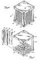
- the plate stack and the frames often may be manufactured at separate locations. Also, it may be desirable to some instances to simply replace the plate stack of a plate block at the use site without removing the frame. For these reasons, among others, it may be desirable to provide the plate stack as an integral unit in condition to be inserted within a frame. In this event, the plates, spacers and other elements of the plate stack itself may be assembled upon a heavy, rigid bottom plate shown in Figure 16 as (134). A heavy, rigid top plate (136) may be placed upon the top-most exchanger plate, and the resulting assembly may be compressed as desired.
- Clamps such as straps (138) may encircle the resulting unit to maintain the compressive force of the plates (134) and (136) upon the plate stack, and the upper plate (136) may be provided with attachment means such as eye bolts (140) so that the plate stack may be lifted by appropriate equipment as a unit and transported to the site of the frame with which the plate stack is to be used.
- the plates (134) and (136) are of sufficient strength as to resist significant bending at their edges due to the strap forces, and the degree of compression between the plates (134) and (136) is such that the plate stack, when supported in a vertical position (that is, with thf planes of the plates extending vertically), will not slip or significantly move with respect to one another. In this manner, the plates themselves are substantially locked together due to friction forces between sucessive plates resulting from the relatively high compression between the plates (134) and (136).
- the pre-compressed plate stack (130) depicted in Figure 16 When the pre-compressed plate stack (130) depicted in Figure 16 is to be installed, it is placed between end walls (104) after removal of the eyebolts (140) and the end walls are positioned adjacent the plates (134) and (136) and are fastened in place with the corner posts (106). Thereafter, the straps (130) may be severed and the plate stack may expand slightly against the end walls.(104).
- the straps (138) desirably are of thin metal, and, although they may be rendered removed entirely, their presence between the plates (136) and the end walls (104) is not harmful to operation of the device.
- the frictional contact between the various elements of the plate stack (130) when the latter is compressed although allowing for movement of the individual plates through thermal expansion, yet is sufficiently great to restrain the plates, by frictional forces therebetween, from gross movement with respect to one another when the plate stack is tipped on edge (with the planes of the plates extending vertically) and the plate stack is supported by the plates (134), (136).
- the plate stack is compressed to a degree restraining the plates from gross movement under a force of two gravities or more, the compression force depending, among other things, upon the number of plates in the stack and the length (measured normal to the planes of the plates) of the plate stack.
- the plate stacks may be turned on edge and transported by truck or other means without incurring damage due to slippage of plates one past another.
- the plates, designated (150), are shaped similarly to the previously described plates (108) but are provided with a plurality of elongated dimples (152) in their heat exchange surfaces.
- the dimples preferably are formed by known metal drawing techniques utilizing appropriately shaped male and female dies. The resulting dimples, accordingly, are pressed outwardly from the plane of the plate and define recesses (154) on one side of the plate and projections (156) on the other side of the plate.
- the dimples preferably are rounded to avoid stress concentrations and for ease of fabrication, and accordingly are generally concave on one side and convex on the other side of the plate.
- the dimples shown in the plates of Figures 17-21 are formed downwardly into each plate, but the direction that the dimples project from the surfaces of the plates is not of importance provided the dimples all project in the same direction when the plates are assembled to form a plate stack.
- the dimples are elongated so that the projecting or convex portions (156) thereof are elongated in the direction of travel of fluid within the channel into which the dimples project, thereby avoiding significant resistance to fluid flow.
- the dimples in the plate of Figure 17, accordingly, are elongated in the direction of fluid flow as shown by the arrow A, whereas the dimples in the next successive plate shown in Figure 20 are elongated in the direction of fluid flow designated by the arrow B.
- the dimples in alternating plates extend in the same direction and are identically positioned in the plates so that the dimples are in alignment in the direction normal to the planes of the plates when the plate stack is assembled.
- the dimples in the remaining alternating plates typified by the plates shown in Figure 20, are elongated in a direction normal to the dimples of the plate shown in Figure 17, and similarly are identically positioned in tha plates so as to be in alignment with one another in a direction normal to the planes of the plates when they are assembled.
- the dimples of the plate in Figure 20 are aligned in a direction normal to the planes of the plates with the dimples of the plates depicted in Figure 17 so that the dimples in successive plates lie in a criss- cross pattern with the intersections being aligned in a direction normal to the planes of the plates.
- Each dimple is sufficiently elongated as to extend beyond the elongated edges of a dimple in an adjacent plate.
- the dimples serve adequately to replace the previously described ribs (122), and, when the plate stack is placed under extreme conditions of temperature or compression, the dimples form, with the respective plate surfaces, structural columns extending normal to the planes of the plates to preserve the correct spacing between plates and to restrain warping.
- the plates (150) desirably are used in heat exchangers intended for lower temperature usage.
- the plates (150) preferably are provided with two opposed edges which have upturned portions (158) and two opposed edges which have downwardly-turned portions (160) and outwardly-turned flanges (162) which nest in the manner shown in Figure 21, the parallel edges of each of the flanges (162) of each plate being received between the upwardly-turned portions (156) of the next adjacent plate.
- the embodiment of Figure 21 utilizes resilient edge separators (164) which, in the particular embodiment depicted, lie directly beneath the flanges (162) and bear downwardly upon the edges of the next consecutive plate adjacent the upwardly-turned portions (158).
- the resilient edge separators may take the form of strips of a resilient rubber such as a silicone rubber.
- Edge spacers (166) may be provided with an elongated, generally serpentine configuration as shown in Figure 21, the spacers (166) having flattened portions (168) resting downwardly upon the flanges (162) and upward, preferably flattened sections (170) upon which the next adjacent plate rests downwardly, with generally straight bridging portions (172) bridging the flattened portions (168) and (170).
- the spacers (166) desirably are rigid and unyielding under the conditions of use.
- the height of the resilient edge separators (164) and the edge spacers (166) may be varied as desired; in the embodiment shown in Figure 21, spaces (174) are provided between the plates at their corners.
- the resilient edge separators (164) may, if desired, be made sufficiently thick at their ends as to occupy the spaces (174), or generally rectangular corner separators of rubber or similar material may be employed to fill the spaces (174).
- the plate stack shown generally at (176) in Figure 21 may be assembled into a heat exchanger plate block as described above in connection with Figures 10 and 11, utilizing similar end plates, corner posts, sealing strips and resilient corner spacers.
- the embodiment shown in Figure 21 may be precompressed into a plate stack in the manner shown in Figure 16, if desired.
- the plates themselves are provided with freedom to grow or expand due to thermal expansion, both internally in a direction normal to the planes of the plates and also externally in a direction parallel to the plate planes, without breakage and without loss of heat transfer utility. Since the plates are not welded, and during normal usage are not subject to breakage, substantial freedom is offered in the selection of plate materials. Materials which would be damaged or whose properties might be altered by welding techniques can readily be used in the instant invention.
- the resilient separators preferably are positioned along the edges of the plates and serve, when compressed, to urge the plate edges against each other to seal the plate edges and reduce or substantially eliminate leakage from one stream to another in a heat transfer operation.
- springy materials may be employed, depending upon the temperature and pressure conditions to be encountered in the heat transfer operation.
- metal mesh of inconel or other alloy may be employed, or ceramic materials may be employed for higher temperature applications, the ceramic desirably being employed in the form of fibrous strips or boards exhibiting some resiliency.
- the resilient spacers enable the individual plates to move slightly with respect to one another in their planes, and accordingly allow for small deviations in alignment as the plates are assembled into a plate stack.
- the plates and other plate stack elements desirably are manufactured in accordance with rigid dimensional specifications
- the use of resilient separators allows for the use of plates and other elements having somewhat greater dimensional tolerances, the springs absorbing small dimensional variances.
- the plates as depicted in the drawing can be manufactured from large sheets or rolls of plate material, and standardized dies can be employed to shape the edges of the plates as desired regardless of the plate size.
- each plate is available for heat transfer, and the size and thinness of the plates may be selected as desired for particular heat transfer applications.
- the heat exchanger plate blocks, complete with frames may be supplied in standardized sizes, enabling a user to assemble one or more blocks together for particular heat exchange operations. Depending upon the materials chosen, heat transfer at substantially any temperature range may be accomplished.
- the relative position of plates within the plate stack is substantially independent of temperature within the selected ranges of use.
- elongated protective grids often are mounted to a frame with the grids overlying and protecting the edges of the plates.
- the alignment of the grids with the plate edges similarly remains substantially constant.
- the heat exchangers of the invention may be employed in substantially any industrial process in which heat is to be exchanged between two streams.
- waste heat in the flue gases emitted by a furnace is transferred to combustion air using a heat exchanger of the invention to heat the air, resulting in reduced waste heat loss.
Landscapes
- Engineering & Computer Science (AREA)
- Physics & Mathematics (AREA)
- Thermal Sciences (AREA)
- Mechanical Engineering (AREA)
- General Engineering & Computer Science (AREA)
- Heat-Exchange Devices With Radiators And Conduit Assemblies (AREA)
- Gas Separation By Absorption (AREA)
Claims (13)
Priority Applications (1)
| Application Number | Priority Date | Filing Date | Title |
|---|---|---|---|
| AT83901769T ATE35573T1 (de) | 1982-04-19 | 1983-04-18 | Waermeaustauscher mit schwimmenden platten. |
Applications Claiming Priority (4)
| Application Number | Priority Date | Filing Date | Title |
|---|---|---|---|
| US36927982A | 1982-04-19 | 1982-04-19 | |
| US369279 | 1982-04-19 | ||
| US480391 | 1983-04-06 | ||
| US06/480,391 US4442886A (en) | 1982-04-19 | 1983-04-06 | Floating plate heat exchanger |
Publications (3)
| Publication Number | Publication Date |
|---|---|
| EP0105922A1 EP0105922A1 (de) | 1984-04-25 |
| EP0105922A4 EP0105922A4 (de) | 1984-08-20 |
| EP0105922B1 true EP0105922B1 (de) | 1988-07-06 |
Family
ID=27004523
Family Applications (1)
| Application Number | Title | Priority Date | Filing Date |
|---|---|---|---|
| EP83901769A Expired EP0105922B1 (de) | 1982-04-19 | 1983-04-18 | Wärmeaustauscher mit schwimmenden platten |
Country Status (6)
| Country | Link |
|---|---|
| US (1) | US4442886A (de) |
| EP (1) | EP0105922B1 (de) |
| AU (1) | AU562135B2 (de) |
| CA (1) | CA1205457A (de) |
| DE (1) | DE3377293D1 (de) |
| WO (1) | WO1983003663A1 (de) |
Cited By (1)
| Publication number | Priority date | Publication date | Assignee | Title |
|---|---|---|---|---|
| WO2023126260A1 (fr) * | 2021-12-30 | 2023-07-06 | Fives Cryo | Echangeur de chaleur comprenant des cales de maintien |
Families Citing this family (54)
| Publication number | Priority date | Publication date | Assignee | Title |
|---|---|---|---|---|
| NZ201673A (en) * | 1981-09-11 | 1986-07-11 | R J Pollard | Flat plate heat exchanger core with diversion elements to allow several fluid passes through core |
| AU571445B2 (en) * | 1982-07-09 | 1988-04-21 | Males Engineering Service | Air to air heat exchanger |
| DE3423736A1 (de) * | 1984-06-28 | 1986-01-02 | M.A.N. Maschinenfabrik Augsburg-Nürnberg AG, 8900 Augsburg | Kreuzstrom-plattenwaermetauscher |
| US4596285A (en) * | 1985-03-28 | 1986-06-24 | North Atlantic Technologies, Inc. | Heat exchanger with resilient corner seals |
| JPS62252891A (ja) * | 1986-04-25 | 1987-11-04 | Sumitomo Heavy Ind Ltd | 向流式浮動プレ−ト型熱交換器 |
| USRE33912E (en) * | 1988-02-09 | 1992-05-05 | Jones Environics Ltd. | Heat exchanger |
| US4848450A (en) * | 1988-02-09 | 1989-07-18 | C & J Jones (1985) Limited | Heat exchanger |
| US5072790A (en) * | 1990-07-30 | 1991-12-17 | Jones Environics Ltd. | Heat exchanger core construction |
| CA2030577C (en) * | 1990-11-23 | 1994-10-11 | Mircea Dinulescu | Plate type heat exchanger |
| CZ286800B6 (cs) * | 1994-12-20 | 2000-07-12 | Mircea Dinulescu | Tepelný výměník |
| JP3829242B2 (ja) * | 1996-02-28 | 2006-10-04 | 敬 高橋 | 扁平配管 |
| US6059025A (en) * | 1998-03-05 | 2000-05-09 | Monsanto Enviro-Chem Systems, Inc. | Heat exchanger configuration |
| ES2150395B1 (es) * | 1999-04-21 | 2001-06-01 | Cortes Jesus Esteban | Sistema intercambiador de calor. |
| US6840313B2 (en) * | 1999-12-27 | 2005-01-11 | Sumitomo Precision Products Co., Ltd. | Plate fin type heat exchanger for high temperature |
| US6267176B1 (en) * | 2000-02-11 | 2001-07-31 | Honeywell International Inc. | Weld-free heat exchanger assembly |
| US6357396B1 (en) | 2000-06-15 | 2002-03-19 | Aqua-Chem, Inc. | Plate type heat exchanger for exhaust gas heat recovery |
| CZ298773B6 (cs) * | 2002-12-19 | 2008-01-23 | Moravia-Apex, S. R. O. | Výměník tepla |
| CA2416508C (en) | 2003-01-17 | 2008-11-18 | Martin Gagnon | A stackable energy transfer core spacer |
| US8276654B2 (en) * | 2005-11-17 | 2012-10-02 | Hamilton Sundstrand Corporation | Core assembly with deformation preventing features |
| SE531472C2 (sv) * | 2005-12-22 | 2009-04-14 | Alfa Laval Corp Ab | Värmeväxlare med värmeöverföringsplatta med jämn lastfördelning på kontaktpunkter vid portområden |
| FR2901016B1 (fr) * | 2006-05-12 | 2008-07-18 | Kapp France Sa | Echangeur de chaleur a plaques d'echange soudees |
| KR101203998B1 (ko) * | 2006-07-18 | 2012-11-23 | 삼성전자주식회사 | 열교환기와 이를 가지는 환기장치 |
| US8646516B2 (en) * | 2006-08-17 | 2014-02-11 | Pana Canada Corporation | Alternating plate headerless heat exchangers |
| EP1930680A1 (de) * | 2006-11-21 | 2008-06-11 | Behr GmbH & Co. KG | Schichtwärmeübertrager mit Entkopplungsvorrichtung |
| FR2930465B1 (fr) * | 2008-04-28 | 2010-09-24 | Air Liquide | Procede de fabrication d'un echangeur de chaleur a plaques utilisant un ensemble de cales |
| FR2930466B1 (fr) * | 2008-04-28 | 2010-09-17 | Air Liquide | Cale pour le maintien des passages d'echangeurs a plaques et ailettes brases |
| DE102008048014A1 (de) * | 2008-09-12 | 2010-04-15 | Esk Ceramics Gmbh & Co. Kg | Bauteil aus einem Stapel keramischer Platten |
| US20110017436A1 (en) * | 2009-07-21 | 2011-01-27 | Shin Han Apex Corporation | Plate type heat exchanger |
| NL2003983C2 (en) | 2009-12-18 | 2011-06-21 | Mircea Dinulescu | Plate type heat exchanger and method of manufacturing heat exchanger plate. |
| NL2004565C2 (en) * | 2010-04-16 | 2011-10-18 | Mircea Dinulescu | Plate type heat exchanger having outer heat exchanger plates with improved connections to end panels. |
| MX346577B (es) * | 2011-07-28 | 2017-03-24 | Nestec Sa | Métodos y dispositivos para calentar o enfriar materiales viscosos. |
| US9803932B2 (en) | 2011-07-28 | 2017-10-31 | Nestec Sa | Methods and devices for heating or cooling viscous materials |
| DK2597412T3 (da) * | 2011-11-28 | 2014-08-11 | Alfa Laval Corp Ab | Blok-type pladevarmeveksler med begroningshæmmende egenskaber |
| RU2493525C1 (ru) * | 2012-02-28 | 2013-09-20 | Федеральное государственное бюджетное образовательное учреждение высшего профессионального образования "Юго-Западный государственный университет" (ЮЗ ГУ) | Пластинчатый теплообменник с естественной подачей охлаждающего воздуха |
| US20140000842A1 (en) * | 2012-06-18 | 2014-01-02 | Tranter, Inc. | Heat exchanger with accessible core |
| WO2014152239A2 (en) * | 2013-03-15 | 2014-09-25 | Thar Energy Llc | Countercurrent heat exchanger/reactor |
| US9777970B2 (en) * | 2013-08-09 | 2017-10-03 | Hamilton Sundstrand Coporation | Reduced thermal expansion closure bars for a heat exchanger |
| US10112270B2 (en) * | 2013-08-21 | 2018-10-30 | Hamilton Sundstrand Corporation | Heat exchanger fin with crack arrestor |
| WO2015028052A1 (de) * | 2013-08-27 | 2015-03-05 | Lux Powertrain S.A. | Rekuperator, mikrogasturbine und verwendung des rekuperators |
| US9746257B2 (en) | 2015-08-11 | 2017-08-29 | Hamilton Sundstrand Corporation | Heat exchanger and fabrication |
| CN105806109B (zh) * | 2016-03-24 | 2020-01-07 | 南京工业大学 | 用于气-气热交换的逆流式翅片板换热器 |
| KR20170111815A (ko) * | 2016-03-29 | 2017-10-12 | 현대자동차주식회사 | 차량용 배기매니폴드 |
| WO2017210602A1 (en) * | 2016-06-03 | 2017-12-07 | Flexenergy | Counter-flow heat exchanger |
| CN106091718A (zh) * | 2016-07-29 | 2016-11-09 | 洛阳文森科技有限公司 | 一种蒸汽轮机高温阶梯换热凝汽器 |
| CN106091724A (zh) * | 2016-07-29 | 2016-11-09 | 洛阳文森科技有限公司 | 一种积木式低气阻凝汽器组件及工艺 |
| WO2018067026A1 (en) * | 2016-10-04 | 2018-04-12 | Deta Engineering Llc | Plate heat exchanger and design of seal unit therefor |
| RU2760724C2 (ru) * | 2017-05-30 | 2021-11-29 | Шелл Интернэшнл Рисерч Маатсхаппий Б.В. | Способ использования непрямого теплообменника и установки для переработки сжиженного природного газа, содержащей такой теплообменник |
| US20190101334A1 (en) * | 2017-10-04 | 2019-04-04 | Larry Baxter | Plate and Frame Heat Exchangers with Variable Chamber Sizes |
| RU2673631C1 (ru) * | 2017-12-25 | 2018-11-28 | Федеральное государственное бюджетное образовательное учреждение высшего образования "Юго-Западный государственный университет" (ЮЗГУ) | Энергосберегающий пластинчатый теплообменник |
| US11022384B2 (en) * | 2018-02-19 | 2021-06-01 | Honeywell International Inc. | Framed heat exchanger core design-fabrication |
| US11035626B2 (en) * | 2018-09-10 | 2021-06-15 | Hamilton Sunstrand Corporation | Heat exchanger with enhanced end sheet heat transfer |
| FR3091581B1 (fr) * | 2019-01-04 | 2021-01-29 | Christian Hug | Plaques en matériau composite formant échangeur de chaleur |
| DE102020203223A1 (de) | 2020-03-12 | 2021-09-16 | Sgl Carbon Se | Plattenwärmetauscher |
| FR3135318B1 (fr) * | 2022-05-04 | 2024-04-19 | Liebherr Aerospace Toulouse Sas | Dispositif d’échange thermique comprenant des plaques externes présentant au moins un évidement, système de conditionnement d’air et véhicule |
Citations (5)
| Publication number | Priority date | Publication date | Assignee | Title |
|---|---|---|---|---|
| US1727124A (en) * | 1928-04-10 | 1929-09-03 | Foster Wheeler Corp | Plate air-heater construction |
| US2368814A (en) * | 1942-05-14 | 1945-02-06 | Bush Mfg Company | Heat exchange unit |
| FR2315674A1 (fr) * | 1975-06-27 | 1977-01-21 | Ferodo Sa | Perfectionnements aux echangeurs de chaleur a plaques |
| US4029146A (en) * | 1974-04-01 | 1977-06-14 | John Zink Company | Corrugated sheet heat exchanger |
| FR2441144A1 (fr) * | 1978-11-10 | 1980-06-06 | Plus Air Groupe | Echangeur de chaleur a plaques |
Family Cites Families (7)
| Publication number | Priority date | Publication date | Assignee | Title |
|---|---|---|---|---|
| US2281754A (en) * | 1937-01-27 | 1942-05-05 | Cherry Burreil Corp | Heat exchanger |
| FR1470506A (fr) * | 1966-03-02 | 1967-02-24 | Marston Excelsior Ltd | échangeur de chaleur |
| US3661203A (en) * | 1969-11-21 | 1972-05-09 | Parkson Corp | Plates for directing the flow of fluids |
| DE2736813A1 (de) * | 1977-08-16 | 1979-03-15 | Froehlich Air Ag | Aluminiumplatten-waermetauscher fuer energierueckgewinnung |
| GB2041190B (en) * | 1979-01-23 | 1982-11-17 | Imi Marston Ltd | Heat exchanger |
| DE2905732C2 (de) * | 1979-02-15 | 1985-07-11 | Interliz Anstalt, Vaduz | Platten-Wärmetauscher |
| US4308915A (en) * | 1980-10-27 | 1982-01-05 | Sanders Nicholas A | Thin sheet heat exchanger |
-
1983
- 1983-04-06 US US06/480,391 patent/US4442886A/en not_active Expired - Lifetime
- 1983-04-18 EP EP83901769A patent/EP0105922B1/de not_active Expired
- 1983-04-18 DE DE8383901769T patent/DE3377293D1/de not_active Expired
- 1983-04-18 AU AU16003/83A patent/AU562135B2/en not_active Expired
- 1983-04-18 WO PCT/US1983/000552 patent/WO1983003663A1/en active IP Right Grant
- 1983-04-19 CA CA000426188A patent/CA1205457A/en not_active Expired
Patent Citations (5)
| Publication number | Priority date | Publication date | Assignee | Title |
|---|---|---|---|---|
| US1727124A (en) * | 1928-04-10 | 1929-09-03 | Foster Wheeler Corp | Plate air-heater construction |
| US2368814A (en) * | 1942-05-14 | 1945-02-06 | Bush Mfg Company | Heat exchange unit |
| US4029146A (en) * | 1974-04-01 | 1977-06-14 | John Zink Company | Corrugated sheet heat exchanger |
| FR2315674A1 (fr) * | 1975-06-27 | 1977-01-21 | Ferodo Sa | Perfectionnements aux echangeurs de chaleur a plaques |
| FR2441144A1 (fr) * | 1978-11-10 | 1980-06-06 | Plus Air Groupe | Echangeur de chaleur a plaques |
Cited By (2)
| Publication number | Priority date | Publication date | Assignee | Title |
|---|---|---|---|---|
| WO2023126260A1 (fr) * | 2021-12-30 | 2023-07-06 | Fives Cryo | Echangeur de chaleur comprenant des cales de maintien |
| FR3131625A1 (fr) * | 2021-12-30 | 2023-07-07 | Fives Cryo | Echangeur de chaleur comprenant des cales de maintien |
Also Published As
| Publication number | Publication date |
|---|---|
| AU1600383A (en) | 1983-11-04 |
| EP0105922A1 (de) | 1984-04-25 |
| US4442886A (en) | 1984-04-17 |
| EP0105922A4 (de) | 1984-08-20 |
| WO1983003663A1 (en) | 1983-10-27 |
| CA1205457A (en) | 1986-06-03 |
| AU562135B2 (en) | 1987-05-28 |
| DE3377293D1 (en) | 1988-08-11 |
Similar Documents
| Publication | Publication Date | Title |
|---|---|---|
| EP0105922B1 (de) | Wärmeaustauscher mit schwimmenden platten | |
| US4343355A (en) | Low stress heat exchanger and method of making the same | |
| US4308915A (en) | Thin sheet heat exchanger | |
| CA1171076A (en) | Heat exchanger | |
| US6357396B1 (en) | Plate type heat exchanger for exhaust gas heat recovery | |
| US4183403A (en) | Plate type heat exchangers | |
| US4229868A (en) | Apparatus for reinforcement of thin plate, high pressure fluid heat exchangers | |
| EP0055711B1 (de) | Wärmetauscher mit flachem profil und verfahren zu seiner herstellung | |
| US4125149A (en) | Heat exchange elements | |
| EP0530188B1 (de) | Ringförmiger wärmetauscher mit gleichförmigem durchgangsquerschnitt | |
| US4385012A (en) | Phase-contacting apparatus | |
| WO1981002060A1 (en) | Low stress heat exchanger and method of making the same | |
| EP0136481A2 (de) | Rippenplatten-Wärmetauscher | |
| GB2203362A (en) | Producing welded plate heat exchangers, more particularly cross-flow plate heat exchangers | |
| US20210389060A1 (en) | Plate for a plate heat exchanger | |
| GB2235040A (en) | Plate heat exchangers | |
| RU2686134C1 (ru) | Пластинчатый теплообменник и способ изготовления пластинчатого теплообменника | |
| RU2659677C1 (ru) | Пластинчатый теплообменник и способ изготовления пластинчатого теплообменника | |
| US20230117804A1 (en) | Plate heat exchanger | |
| JPH0348438B2 (de) | ||
| CN210624568U (zh) | 一种燃气锅炉板式空气预热器 | |
| FI78983C (fi) | Plattvaermevaexlare. | |
| JPS6176889A (ja) | プレ−ト型熱交換器 | |
| FR2496863B1 (fr) | Echangeur de chaleur modulaire a flux croises et son procede de fabrication | |
| JPH053913Y2 (de) |
Legal Events
| Date | Code | Title | Description |
|---|---|---|---|
| PUAI | Public reference made under article 153(3) epc to a published international application that has entered the european phase |
Free format text: ORIGINAL CODE: 0009012 |
|
| 17P | Request for examination filed |
Effective date: 19831213 |
|
| AK | Designated contracting states |
Designated state(s): AT BE CH DE FR GB LI LU NL SE |
|
| GRAA | (expected) grant |
Free format text: ORIGINAL CODE: 0009210 |
|
| AK | Designated contracting states |
Kind code of ref document: B1 Designated state(s): AT BE CH DE FR GB LI LU NL SE |
|
| REF | Corresponds to: |
Ref document number: 35573 Country of ref document: AT Date of ref document: 19880715 Kind code of ref document: T |
|
| REF | Corresponds to: |
Ref document number: 3377293 Country of ref document: DE Date of ref document: 19880811 |
|
| RAP4 | Party data changed (patent owner data changed or rights of a patent transferred) |
Owner name: NORTH ATLANTIC TECHNOLOGIES INC. |
|
| ET | Fr: translation filed | ||
| PLBE | No opposition filed within time limit |
Free format text: ORIGINAL CODE: 0009261 |
|
| STAA | Information on the status of an ep patent application or granted ep patent |
Free format text: STATUS: NO OPPOSITION FILED WITHIN TIME LIMIT |
|
| 26N | No opposition filed | ||
| EPTA | Lu: last paid annual fee | ||
| EAL | Se: european patent in force in sweden |
Ref document number: 83901769.6 |
|
| PGFP | Annual fee paid to national office [announced via postgrant information from national office to epo] |
Ref country code: SE Payment date: 20000406 Year of fee payment: 18 |
|
| PGFP | Annual fee paid to national office [announced via postgrant information from national office to epo] |
Ref country code: FR Payment date: 20000411 Year of fee payment: 18 |
|
| PGFP | Annual fee paid to national office [announced via postgrant information from national office to epo] |
Ref country code: AT Payment date: 20000412 Year of fee payment: 18 |
|
| PGFP | Annual fee paid to national office [announced via postgrant information from national office to epo] |
Ref country code: DE Payment date: 20000417 Year of fee payment: 18 |
|
| PGFP | Annual fee paid to national office [announced via postgrant information from national office to epo] |
Ref country code: LU Payment date: 20000419 Year of fee payment: 18 |
|
| PGFP | Annual fee paid to national office [announced via postgrant information from national office to epo] |
Ref country code: CH Payment date: 20000427 Year of fee payment: 18 |
|
| PGFP | Annual fee paid to national office [announced via postgrant information from national office to epo] |
Ref country code: NL Payment date: 20000428 Year of fee payment: 18 |
|
| PGFP | Annual fee paid to national office [announced via postgrant information from national office to epo] |
Ref country code: BE Payment date: 20000622 Year of fee payment: 18 |
|
| REG | Reference to a national code |
Ref country code: GB Ref legal event code: 732E |
|
| REG | Reference to a national code |
Ref country code: GB Ref legal event code: 732E |
|
| PG25 | Lapsed in a contracting state [announced via postgrant information from national office to epo] |
Ref country code: LU Free format text: LAPSE BECAUSE OF NON-PAYMENT OF DUE FEES Effective date: 20010418 Ref country code: AT Free format text: LAPSE BECAUSE OF NON-PAYMENT OF DUE FEES Effective date: 20010418 |
|
| PG25 | Lapsed in a contracting state [announced via postgrant information from national office to epo] |
Ref country code: SE Free format text: LAPSE BECAUSE OF NON-PAYMENT OF DUE FEES Effective date: 20010419 |
|
| PG25 | Lapsed in a contracting state [announced via postgrant information from national office to epo] |
Ref country code: FR Free format text: THE PATENT HAS BEEN ANNULLED BY A DECISION OF A NATIONAL AUTHORITY Effective date: 20010430 Ref country code: BE Free format text: LAPSE BECAUSE OF NON-PAYMENT OF DUE FEES Effective date: 20010430 |
|
| PG25 | Lapsed in a contracting state [announced via postgrant information from national office to epo] |
Ref country code: LI Free format text: LAPSE BECAUSE OF NON-PAYMENT OF DUE FEES Effective date: 20010517 Ref country code: CH Free format text: LAPSE BECAUSE OF NON-PAYMENT OF DUE FEES Effective date: 20010517 |
|
| BERE | Be: lapsed |
Owner name: NORTH ATLANTIC TECHNLOGIES INC. Effective date: 20010430 |
|
| PG25 | Lapsed in a contracting state [announced via postgrant information from national office to epo] |
Ref country code: NL Free format text: LAPSE BECAUSE OF NON-PAYMENT OF DUE FEES Effective date: 20011101 |
|
| EUG | Se: european patent has lapsed |
Ref document number: 83901769.6 |
|
| REG | Reference to a national code |
Ref country code: CH Ref legal event code: PL |
|
| REG | Reference to a national code |
Ref country code: GB Ref legal event code: IF02 |
|
| NLV4 | Nl: lapsed or anulled due to non-payment of the annual fee |
Effective date: 20011101 |
|
| PG25 | Lapsed in a contracting state [announced via postgrant information from national office to epo] |
Ref country code: DE Free format text: LAPSE BECAUSE OF NON-PAYMENT OF DUE FEES Effective date: 20020201 |
|
| REG | Reference to a national code |
Ref country code: FR Ref legal event code: ST |
|
| PGFP | Annual fee paid to national office [announced via postgrant information from national office to epo] |
Ref country code: GB Payment date: 20020417 Year of fee payment: 20 |
|
| PG25 | Lapsed in a contracting state [announced via postgrant information from national office to epo] |
Ref country code: GB Free format text: LAPSE BECAUSE OF EXPIRATION OF PROTECTION Effective date: 20030417 |
|
| REG | Reference to a national code |
Ref country code: GB Ref legal event code: PE20 |