EP0105127A1 - Umlaufverdichter - Google Patents
Umlaufverdichter Download PDFInfo
- Publication number
- EP0105127A1 EP0105127A1 EP19830107665 EP83107665A EP0105127A1 EP 0105127 A1 EP0105127 A1 EP 0105127A1 EP 19830107665 EP19830107665 EP 19830107665 EP 83107665 A EP83107665 A EP 83107665A EP 0105127 A1 EP0105127 A1 EP 0105127A1
- Authority
- EP
- European Patent Office
- Prior art keywords
- sealed container
- oil
- lubricating oil
- rotary compressor
- gas
- Prior art date
- Legal status (The legal status is an assumption and is not a legal conclusion. Google has not performed a legal analysis and makes no representation as to the accuracy of the status listed.)
- Granted
Links
- 239000010687 lubricating oil Substances 0.000 claims abstract description 63
- 230000006835 compression Effects 0.000 claims abstract description 48
- 238000007906 compression Methods 0.000 claims abstract description 48
- 230000000694 effects Effects 0.000 claims abstract description 5
- 238000005461 lubrication Methods 0.000 claims abstract description 4
- 239000003921 oil Substances 0.000 claims description 80
- 239000002826 coolant Substances 0.000 claims description 21
- 230000001939 inductive effect Effects 0.000 claims description 9
- 238000001816 cooling Methods 0.000 claims description 8
- 230000003584 silencer Effects 0.000 claims description 5
- 230000002093 peripheral effect Effects 0.000 claims description 3
- 238000007599 discharging Methods 0.000 description 13
- 238000010276 construction Methods 0.000 description 6
- 230000030279 gene silencing Effects 0.000 description 6
- 230000005764 inhibitory process Effects 0.000 description 6
- 238000007789 sealing Methods 0.000 description 6
- 230000006866 deterioration Effects 0.000 description 4
- 230000001050 lubricating effect Effects 0.000 description 4
- 230000037431 insertion Effects 0.000 description 3
- 238000003780 insertion Methods 0.000 description 3
- 239000011810 insulating material Substances 0.000 description 3
- 230000003247 decreasing effect Effects 0.000 description 2
- 230000003190 augmentative effect Effects 0.000 description 1
- 238000009434 installation Methods 0.000 description 1
- 238000004519 manufacturing process Methods 0.000 description 1
- 238000005476 soldering Methods 0.000 description 1
Images


Classifications
-
- F—MECHANICAL ENGINEERING; LIGHTING; HEATING; WEAPONS; BLASTING
- F04—POSITIVE - DISPLACEMENT MACHINES FOR LIQUIDS; PUMPS FOR LIQUIDS OR ELASTIC FLUIDS
- F04C—ROTARY-PISTON, OR OSCILLATING-PISTON, POSITIVE-DISPLACEMENT MACHINES FOR LIQUIDS; ROTARY-PISTON, OR OSCILLATING-PISTON, POSITIVE-DISPLACEMENT PUMPS
- F04C29/00—Component parts, details or accessories of pumps or pumping installations, not provided for in groups F04C18/00 - F04C28/00
- F04C29/02—Lubrication; Lubricant separation
Definitions
- This invention relates to a rotary compressor, and, more particularly, it is concerned with the rotary compressor of a type, in which lubricating oil is cooled by a heat-exchanger for improving the performance and reliability in its operation.
- the present invention aims at improving those disadvantages inherent in the conventional compressor so as to provide such compressing machine which can be assembled readily and has excellent operational performance and reliability.
- a rotary compressor which comprises: a compression chamber defined by enclosing both ends of a cylinder with a main bearing and an end bearing; compression elements including a piston which is eccentrically rotated by a crank shaft within the compression chamber, and dividing the compression chamber into a high pressure chamber and a low pressure chamber; and a sealed container to be a plenum space, in which the compression elements are housed and lubricating oil is sumped at the inner bottom section of the sealed container to effect lubrication of sliding parts of the compression elements, wherein the lubricating oil is returned into the sealed container after it has been cooled through a heat-exchanger provided outside the sealed container.
- a horizontal type rotary compressor which comprises: a compression chamber defined by enclosing both ends of a cylinder with a main bearing and an end bearing; compression elements including a piston which is eccentrically rotated by a crank shaft within the compression chamber, and dividing the compression chamber into a high pressure chamber and a low pressure chamber; and a sealed container to form a plenum space, in which the compression elements are housed and lubricating oil is sumped at the inner bottom section of the sealed container to perform lubrication of sliding parts of the compression elements, wherein there are further provided a communicating port formed in said cylinder so as to introduce discharged coolant gas from the compression chamber; a large diameter section of said communicating port, which is expanded in the lubricating oil; an ejecting pipe, one end of which is inserted into said communicating port and opened in said large diameter section thereof; and an oil inducing path which intersects orthogonally with said large diameter section and passes through said cylinder, the lubric
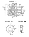
- Figure 1 is a cross-sectional view of the rotary compressor according to the first embodiment of the present invention
- Figure 2 is a perspective view of the main part of the rotary compressor according to the first embodiment of the present invention.
- a reference numeral 1 designates a hermetically sealed container
- numerals 2 and 3 refer respectively to an electric motor and compression elements housed in the hermetically sealed container
- numeral 7 refers to a crank shaft to be driven by the electric motor 2, and others.
- the above-mentioned compression elements 3 comprise a piston 8 fitted on the crank shaft, a vane (not shown in the drawing) with its one end being in contact with the piston and performing reciprocating motion, main and end bearings 5, 6 to support the above-mentioned crank shaft 7, and a cylinder 4 provided in between the two bearings.
- the interior of this cylinder is divided by the above-mentioned vane, as is well known, into a high pressure chamber and a low pressure chamber for the coolant so that inlet and outlet of the coolant can be repeated by the eccentric rotation of the crank shaft 7.
- the coolant gas compressed in the above-described manner passes through a discharge port 12 and a discharge valve 13 formed in and provided on the main bearing 5, and discharged into a silencing chamber 14 provided at the outside of the main bearing to the discharge side of the coolant.
- a numeral 15 refers to a gas passage hole through the cylinder 4 between the main bearing 5 and the end bearing 6.
- a reference numeral 16 denotes a gas discharge tube with its fixed end being inserted into this gas passage hole, the other end of the gas discharge tube being a gas discharging end portion 16a which is opened in an oil guiding tube 17, one end of which is also opened in the lubricating oil 19 sumped in the hermetically sealed container 1.
- This oil guiding tube (or oil feeding tube) 17 is opened:, at the other end thereof, in the sealed container through a heat-exchanger 18 provided at the outside thereof.
- the discharged gas from the compression chamber is led into a lubricating oil feeding end 17a of the oil feeding tube 17 through the discharge end portion 16a of the gas discharge tube 16.
- the lubricating oil 19 standing at the bottom part of the sealed container 1 is drawn into the oil feeding tube 17 through a gap A formed in an overlapped portion between the gas discharge tube and the oil feeding tube, is forwarded to the heat-exchanger 18 provided outside the sealed container together with an ejected gas from the gas discharge tube, and is fed back into the sealed container 1 again through a feeding end portion 17b.
- the lubricating oil at the inner bottom part of the sealed container circulates in the oil feeding tube, while discharging heat, whereby it keeps discharging heat transmitted from the electric motor, the compression elements, and so on.
- the temperature of the compressor as a whole inclusive of the compression elements, the lubricating oil, and so on is lowered with the consequence that not only the performance of the compressor improves due to inhibition against preheating of the intake gas, improvement in sealing against leakage of the lubricating oil, etc., but also reliability of the device such as improvement in the lubricating property, etc. becomes effectively augmented.
- the temperature in the electric motor element 2, the compression elements 3, the lubricating oil 19, and so forth can be lowered, whereby the temperature of the compressor as a whole can be decreased.
- the performance of the compressor improves due to inhibition against preheating of the intake gas, improvement in sealing against leakage of the lubricating oil, improvement in the operating efficiency of the motor, and so forth, and the reliability of the compressor also improves due to inhibition against deterioration of the insulating material for the electric motor.
- the coolant gas which has been drawn in from the intake tube 9 and compressed passes through the discharge port 12 and the discharge valve 13 formed in and provided on the main bearing 5, and discharged into the silencing chamber 14 at the discharge side, after which it further passes through the gas passage hole 15 through the main and end bearings 5, 6 and the cylinder 4 therebetween, and then is led into the gas discharge tube 16, the fixed end of which is inserted into the gas.passage hole.
- the compressed coolant gas from the compression chamber is discharged into the oil feeding tube 30 from the end part of the gas discharge tube 30.
- the lubricating oil standing at the bottom part of the sealed container 1 is sucked into the discharge tube 16 through a gap 33 formed in the overlapped section between the discharge tube 16 and the oil feeding tube 30, which passes through the heat-exchanger 31 provided outside the sealed container 1, and is again sent into the sealed container.
- the third embodiment of the present invention causes the lubricating oil to circulate, while discharging heat through the heat-exchanger.
- the temperature in the compression elements, the electric motor element, further the lubricating oil, and so forth becomes lowered, hence the temperature of the compressor as a whole can be decreased, and also the performance of the compressor can be improved due to inhibition against preheating of the intake gas, improvement in sealing against leakage of the lubricating oil, improvement in working efficiency of the electric motor, and others.
- reliability of the compressor can be remarkably improved as the result of improvement in the lubricating performance, inhibtion against deterioration in the insulating material for the electric motor elements, and so forth.
- the internal space of the compressor can be reduced, which contributes to realizing reduction in size of the compressor.
- a reference numeral 41 designates the sealed container; numerals 42, 43 respectively refer to the electric motor section and the compression elements housed in the sealed container; and a numeral 47 refers to the crank shaft to be driven by the electric motor section 42, etc., which is disposed in the horizontal direction.
- the compression elements 43 comprises the piston 48 fitted onto the crank shaft, the vane (not shown in the drawing) with its one end being in contact with the piston, and which performs its reciprocating motion, the main and end bearings 45, 46 to support the crank shaft 47, and the cylinder 44 positioned between the two bearings.
- the interior of this cylinder is divided, as is well known, by the above-mentioned vane into the high pressure chamber and the low pressure chamber so that the inlet and outlet of the coolant may be repeated by the eccentric rotation of the crank shaft 47.
- the coolant gas which has been compressed in the above-mentioned manner passes through the discharging valve 53 provided on the main bearing 45, and is discharged into the silencing chamber 54 at its discharge side provided outside the main bearing 45.
- a reference numeral 55 denotes the gas passage hole through the main and end bearings 45, 46 and the cylinder 44 disposed between them.
- a reference numeral 56 designates a communciating port which is formed through in such a manner that one end of it is open to the lower surface of the cylinder 43, and the other end thereof is open at a position away from the open end 55a of the gas passage hole which is open to the above-mentioned end bearing 46.
- This communicating port has a large diameter section 57 in the vicinity of the lower end of the cylinder where its diameter is expanded.
- a reference numeral 58 indicates an ejecting pipe with its one end being inserted into this communicating port and with its other end being opened in the large diameter section 57 contiguous to the sealed container 41. This ejecting pipe forms a space gap between its outer periphery and the large diameter section.
- a numeral 59 refers to an oil inducing path which passes through the cylinder 43 interior so as to be opposed to the side surface of the ejecting pipe 58. This oil inducing path is opened in the lubricating oil 60 standing at the inner bottom part of the sealed container 41.
- a reference numeral 61 designates an oil feeding pipe, one end of which is connected with a bar ring 62 opened to the lower surface wall of the sealed container 41 in opposition to the above-mentioned large diameter section 57, and the other end of which is connected with the oil feeding path 63 provided in the cylinder 43 passing through the upper surface wall of the sealed container 41.
- a numeral 64 refers to the heat-exchanger which is connected intermediate of the oil feeding pipe, and provided outside the sealed container.
- a numeral 65 refers to an oil sump vessel in a substantially cup-shape having an oil sump section between the end surfaces of the end bearing 46.
- the oil sump vessel has a flange portion 65a to fit on the outer surface of the end bearing 46, and forms a gas flow path 66 by bulging out the above-mentioned flange portion 65a in a manner as to connecting the open end of the gas passage hole 55a in the end bearing 46 and the open end 56a of the communicating port. Moreover, these oil sump vessel 65 and the oil feeding pipe 63 are connected by the oil feeding pipe 61.
- a reference numeral 67 denotes an oil feeding port passing concentrically through the above-mentioned crank shaft 47. By this oil feeding port, oil is fed to the sliding parts through a branch port 67a.
- the discharged gas from the compression chamber passes through the silencing chamber 54 at the discharge side thereof and the gas passage hole 55, and is led into the ejecting pipe 58 in the communicating port through the gas flow path formed in the above-mentioned oil sump vessel 65.
- the lubricating oil at the inner bottom part of the sealed container circulates, while discharging heat, whereby it continues to discharge heat to be transmitted from the electric motor section, the compression elements, and others.
- the temperature of the compression elements, the lubricating oil, etc. hence the temperature of the compressor as a whole, is lowered.
- the performance of the compressor improves due to inhibition against preheating of the intake gas, improvements in the sealing property of the lubricating oil, etc., but also the effect to reliability of the operation of the device such as improvement in the lubricating performance, etc. is also great.
- a reference numeral 70 is designated by the gas passage hole which passes through the main bearing 45 at a position close to the discharge valve 53 and through the cylinder 44 in a shape of a letter "L" , and is opened toward the lower surface of the cylinder in its radial direction.
- This gas passage hole is joined with the communicating port 71 of a large diameter.
- the external heat-exchanger 64 for cooling the lubricating oil is connected with the large diameter part of the communicating port 71 at the outer peripheral part of the cylinder through the pipe 75.
- the other end of the heat-exchanger 64 is communicatively connected with the substantially cup-shaped oil sump vessel 77 which has been press-fitted on the outer periphery of the flanged part of the end bearing 46 through the oil guiding pipe 76 passing through the sealed container 41, whereby the lubricating oil in this oil sump vessel is distributed to each of the sliding parts through the oil feeding ports (not shown in the drawing) opened in the above-mentioned crank shaft 47. Further, the outer peripheral part of this oil sump vessel is press-fitted in and fixed on the flange portion of the end bearing 46.
- the discharged coolant gas from the compression chamber passes through the silencing chamber 54 at the discharge side and the gas passage hole 70, and is ejected from the above-mentioned ejecting pipe 72 within the entrance portion of the heat-exchanger, i.e., within the large diameter portion. of the communicating port 71. Then, it is sent into the heat-exchanger 64 provided outside the sealed container together with the lubricating oil 60 drawn thereinto through the space gap 74 at the overlapped portion between the inner diameter portion of the communicating port 71 and the outer diameter portion of the ejecting pipe 72. After the heat-exchange, the gas is sent back into the sealed container again.
- the lubricating oil is sent back into the above-mentioned substantially cup-shaped oil sump vessel 77 through the oil guiding pipe 76 in the sealed container. After this, the lubricating oil is distributed to each of the sliding parts, while the coolant gas is discharged into the sealed container from the end surface of the crank shaft 47 at the side of the electric motor.
- the lubricating oil at the inner bottom part of the sealed container circulates, while discharging heat, whereby it continues to discharge heat to be transmitted from the electric motor section, the compression elements, and others.
- the temperature of the compressor as a whole including the compression elements, the lubricating oil, and so on is lowered, not only the performance of the compressor improves due to inhibition against preheating of the intake gas, improvement in the sealing property against leakage of the lubricating oil, and so forth, but also the effect to reliability of the compressor such as improvement in the lubricating performance, etc. is also great.
- the compressor can be installed either in the horizontal direction or in the vertical direction, whereby the best mode of its use with good space saving installation can be expected.
- a reference numeral 80 designates the discharge valve which is provided at the side of the end bearing (cylinder head) 6, and the discharge silencer 81 is mounted at the side of the cylinder head 6, i.e. , at the lower surface side of the cylinder 4.
- a numeral 82 refers to an intromitting port for the oil feeding pipe, which is formed in the lower side surface of the hermetically sealed container 1 where the lubricating oil 19 gathers.
- the manner of insertion is such that, after the compression elements 3 and the electric motor element 2 have been inserted into the hermetically sealed container 1, a connecting tube 83 which has previously been set in the oil guiding pipe 17 is inserted into the bar ring hole 84 formed in the discharge silencer 81 from the oil guiding pipe intro- nitting port 82.
- the diameter of the bar ring hole 84 and that of the connecting tube 83 to be inserted into this bar ring hole is substantially same, so that they are tightly fitted and sealed by insertion into the other.
- the pipe 17 is hermetically fusion-bonded by soldering to the oil guiding pipe intromitting port.
- the sixth embodiment of the present invention is so constructed that the oil guiding pipe 17 is directly inserted into the discharge silencer 81, the pressure loss at the connecting hole becomes eliminated in comparison with the case of the Figure 2 embodiment.
- the coolant gas is taken out from the side surface of the hermetically sealed container, a difference in height between the oil feeding port and the oil returning port can be reduced.
Landscapes
- Engineering & Computer Science (AREA)
- Mechanical Engineering (AREA)
- General Engineering & Computer Science (AREA)
- Applications Or Details Of Rotary Compressors (AREA)
Applications Claiming Priority (12)
| Application Number | Priority Date | Filing Date | Title |
|---|---|---|---|
| JP15031982A JPS5939991A (ja) | 1982-08-30 | 1982-08-30 | 回転式圧縮機 |
| JP150319/82 | 1982-08-30 | ||
| JP14847482U JPS5952198U (ja) | 1982-09-30 | 1982-09-30 | 横置形回転式圧縮機 |
| JP148473/82 | 1982-09-30 | ||
| JP148474/82 | 1982-09-30 | ||
| JP14847382U JPS5952197U (ja) | 1982-09-30 | 1982-09-30 | 回転式圧縮機 |
| JP157697/82 | 1982-10-19 | ||
| JP15769782U JPS5962289U (ja) | 1982-10-19 | 1982-10-19 | 回転式圧縮機の潤滑油冷却装置 |
| JP17527882U JPS5979574U (ja) | 1982-11-19 | 1982-11-19 | 回転式圧縮機 |
| JP17527982U JPS5979575U (ja) | 1982-11-19 | 1982-11-19 | 密閉形回転式圧縮機 |
| JP175279/82 | 1982-11-19 | ||
| JP175278/82 | 1982-11-19 |
Publications (2)
| Publication Number | Publication Date |
|---|---|
| EP0105127A1 true EP0105127A1 (de) | 1984-04-11 |
| EP0105127B1 EP0105127B1 (de) | 1987-06-16 |
Family
ID=27553044
Family Applications (1)
| Application Number | Title | Priority Date | Filing Date |
|---|---|---|---|
| EP19830107665 Expired EP0105127B1 (de) | 1982-08-30 | 1983-08-04 | Umlaufverdichter |
Country Status (5)
| Country | Link |
|---|---|
| EP (1) | EP0105127B1 (de) |
| AU (1) | AU548548B2 (de) |
| DE (1) | DE3372117D1 (de) |
| DK (1) | DK156672C (de) |
| MX (2) | MX153949A (de) |
Cited By (4)
| Publication number | Priority date | Publication date | Assignee | Title |
|---|---|---|---|---|
| EP0173013A2 (de) * | 1984-06-25 | 1986-03-05 | Mitsubishi Denki Kabushiki Kaisha | Drehverdichter |
| EP0195560A2 (de) * | 1985-03-14 | 1986-09-24 | Kabushiki Kaisha Toshiba | Drehkolbenkompressor |
| AU585439B2 (en) * | 1987-04-14 | 1989-06-15 | Mitsubishi Denki Kabushiki Kaisha | Rotary compressor |
| CN114017334A (zh) * | 2021-11-08 | 2022-02-08 | 广东美芝制冷设备有限公司 | 旋转压缩机及具有其的制冷设备 |
Citations (4)
| Publication number | Priority date | Publication date | Assignee | Title |
|---|---|---|---|---|
| GB382227A (en) * | 1931-05-15 | 1932-10-20 | Bosch Robert | Improvements in or relating to refrigerating machines |
| US1967035A (en) * | 1933-05-08 | 1934-07-17 | Lipman Patents Corp | Motor compressor unit |
| US2178425A (en) * | 1937-02-18 | 1939-10-31 | Gen Electric | Refrigerating machine |
| US2623365A (en) * | 1947-07-14 | 1952-12-30 | Leonard J Daniel | Refrigerator pump |
-
1983
- 1983-08-04 AU AU17607/83A patent/AU548548B2/en not_active Ceased
- 1983-08-04 DE DE8383107665T patent/DE3372117D1/de not_active Expired
- 1983-08-04 EP EP19830107665 patent/EP0105127B1/de not_active Expired
- 1983-08-25 DK DK389183A patent/DK156672C/da not_active IP Right Cessation
- 1983-08-29 MX MX19853483A patent/MX153949A/es unknown
- 1983-08-29 MX MX56783A patent/MX158883A/es unknown
Patent Citations (4)
| Publication number | Priority date | Publication date | Assignee | Title |
|---|---|---|---|---|
| GB382227A (en) * | 1931-05-15 | 1932-10-20 | Bosch Robert | Improvements in or relating to refrigerating machines |
| US1967035A (en) * | 1933-05-08 | 1934-07-17 | Lipman Patents Corp | Motor compressor unit |
| US2178425A (en) * | 1937-02-18 | 1939-10-31 | Gen Electric | Refrigerating machine |
| US2623365A (en) * | 1947-07-14 | 1952-12-30 | Leonard J Daniel | Refrigerator pump |
Cited By (7)
| Publication number | Priority date | Publication date | Assignee | Title |
|---|---|---|---|---|
| EP0173013A2 (de) * | 1984-06-25 | 1986-03-05 | Mitsubishi Denki Kabushiki Kaisha | Drehverdichter |
| EP0173013A3 (en) * | 1984-06-25 | 1987-01-14 | Mitsubishi Denki Kabushiki Kaisha | Rotary compressor |
| EP0195560A2 (de) * | 1985-03-14 | 1986-09-24 | Kabushiki Kaisha Toshiba | Drehkolbenkompressor |
| EP0195560A3 (en) * | 1985-03-14 | 1988-06-01 | Kabushiki Kaisha Toshiba | Rotary compressor |
| AU585439B2 (en) * | 1987-04-14 | 1989-06-15 | Mitsubishi Denki Kabushiki Kaisha | Rotary compressor |
| CN114017334A (zh) * | 2021-11-08 | 2022-02-08 | 广东美芝制冷设备有限公司 | 旋转压缩机及具有其的制冷设备 |
| CN114017334B (zh) * | 2021-11-08 | 2023-09-05 | 广东美芝制冷设备有限公司 | 旋转压缩机及具有其的制冷设备 |
Also Published As
| Publication number | Publication date |
|---|---|
| DK156672B (da) | 1989-09-18 |
| EP0105127B1 (de) | 1987-06-16 |
| DK389183D0 (da) | 1983-08-25 |
| DK389183A (da) | 1984-03-01 |
| AU1760783A (en) | 1984-03-08 |
| AU548548B2 (en) | 1985-12-19 |
| MX158883A (es) | 1989-03-29 |
| DE3372117D1 (en) | 1987-07-23 |
| DK156672C (da) | 1990-02-12 |
| MX153949A (es) | 1987-02-24 |
Similar Documents
| Publication | Publication Date | Title |
|---|---|---|
| US4569645A (en) | Rotary compressor with heat exchanger | |
| EP0173013B1 (de) | Drehverdichter | |
| US7473079B2 (en) | Electric compressor with inverter | |
| US4385875A (en) | Rotary compressor with fluid diode check value for lubricating pump | |
| KR970003262B1 (ko) | 전동압축기 | |
| US7074024B2 (en) | Scroll-type fluid machine having a path to pass and cool the fluid | |
| EP0569119B1 (de) | Drehkolbenverdichter | |
| CA1246507A (en) | Oil dispersing device | |
| EP0588381B1 (de) | Hermetischer Verdichter | |
| KR19980081422A (ko) | 방출덕트를 갖춘 스크롤머신 | |
| EP0105127A1 (de) | Umlaufverdichter | |
| US4968223A (en) | Gas and oil cooling system for a hermetic compressor | |
| US4502854A (en) | Vane compressor having rearwardly located suction connector and discharge connector | |
| JP4167456B2 (ja) | 電動圧縮機 | |
| US4400142A (en) | Motor-compressor unit | |
| EP0322531A2 (de) | Gasleit der Schalldämpfungseinrichtung für Drehkolbenverdichter | |
| JPS6213786A (ja) | 密閉形圧縮機 | |
| CN110848135B (zh) | 卧式压缩机及热交换工作设备 | |
| CN217029317U (zh) | 一种转子压缩机、一种压缩机组件和一种空调器室外机 | |
| CN215949826U (zh) | 一种压缩机壳体和压缩机 | |
| JPS6350695A (ja) | ロ−タリコンプレツサ | |
| JP2563591B2 (ja) | スクロール圧縮機 | |
| JPH0626473A (ja) | スクロール圧縮機 | |
| JPS6336072A (ja) | 電動圧縮機 | |
| JP2538062B2 (ja) | スクロ―ル圧縮機 |
Legal Events
| Date | Code | Title | Description |
|---|---|---|---|
| PUAI | Public reference made under article 153(3) epc to a published international application that has entered the european phase |
Free format text: ORIGINAL CODE: 0009012 |
|
| AK | Designated contracting states |
Designated state(s): DE FR GB IT SE |
|
| 17P | Request for examination filed |
Effective date: 19840409 |
|
| GRAA | (expected) grant |
Free format text: ORIGINAL CODE: 0009210 |
|
| AK | Designated contracting states |
Kind code of ref document: B1 Designated state(s): DE FR GB IT SE |
|
| ITF | It: translation for a ep patent filed | ||
| REF | Corresponds to: |
Ref document number: 3372117 Country of ref document: DE Date of ref document: 19870723 |
|
| ET | Fr: translation filed | ||
| PLBE | No opposition filed within time limit |
Free format text: ORIGINAL CODE: 0009261 |
|
| STAA | Information on the status of an ep patent application or granted ep patent |
Free format text: STATUS: NO OPPOSITION FILED WITHIN TIME LIMIT |
|
| 26N | No opposition filed | ||
| PGFP | Annual fee paid to national office [announced via postgrant information from national office to epo] |
Ref country code: GB Payment date: 19890731 Year of fee payment: 7 |
|
| PGFP | Annual fee paid to national office [announced via postgrant information from national office to epo] |
Ref country code: FR Payment date: 19890808 Year of fee payment: 7 |
|
| PGFP | Annual fee paid to national office [announced via postgrant information from national office to epo] |
Ref country code: SE Payment date: 19890810 Year of fee payment: 7 |
|
| ITTA | It: last paid annual fee | ||
| PGFP | Annual fee paid to national office [announced via postgrant information from national office to epo] |
Ref country code: DE Payment date: 19890929 Year of fee payment: 7 |
|
| PG25 | Lapsed in a contracting state [announced via postgrant information from national office to epo] |
Ref country code: GB Effective date: 19900804 |
|
| PG25 | Lapsed in a contracting state [announced via postgrant information from national office to epo] |
Ref country code: SE Effective date: 19900805 |
|
| GBPC | Gb: european patent ceased through non-payment of renewal fee | ||
| PG25 | Lapsed in a contracting state [announced via postgrant information from national office to epo] |
Ref country code: FR Effective date: 19910430 |
|
| PG25 | Lapsed in a contracting state [announced via postgrant information from national office to epo] |
Ref country code: DE Effective date: 19910501 |
|
| REG | Reference to a national code |
Ref country code: FR Ref legal event code: ST |
|
| EUG | Se: european patent has lapsed |
Ref document number: 83107665.8 Effective date: 19910410 |